


 nueva página del texto (beta)
 Inglés (pdf)
 Artículo en XML
 Referencias del artículo
 Enviar artículo por email
 Citado por SciELO
  Similares en
SciELO
Similares en
SciELO 
 Permalink
Introduction
The importance of the study of nanostructures with chemical relevance based on regular shapes relies on the gain of a simple vision or explanation of their featured complexity (i.e., metal clusters, metal-organic frameworks, complex metallic alloys, and so on). The process of structural simplification can be fueled by using symmetry elements, and the visualization might be facilitated by an object-oriented language. In materials science and structural chemistry, the spatial vision is recognized as valuable in the understanding of bonding and structure. Certainly, the training of second-year undergraduate students requires the use of programming tools to facilitate the assimilation of concepts as topology, bonding, and all covered subjects in materials chemistry and computational chemistry courses (Morales-Vidales et al., 2020). In other words, the study of regular shapes is inherent to structural chemistry, where a simplification of complex structures is done by using polyhedral building blocks. In literature the use of regular shapes to describe the bonding in Boron clusters is plenty and they have been modeled/determined with octahedral and tetrahedral symmetries (Hayami and Otani, 2011; Wang, 2016). Interestingly, the snub Archimedean solids (snub cube and snub dodecahedron) features the property of chirality depending on the direction of applied rotation. For example, the B60 molecule was proposed as a chiral distorted snub dodecahedron (Zope y Baruah, 2011). Another interesting systems displaying regular shapes (Platonic, Archimedean and Catalan solids) are gold nanoparticles whose morphology depends on the content of water and a capping agent known as poly(vinyl pyrrolidone) (Kim et al., 2010). The Archimedean solids have also been realized as candidates of carbon structures, and the proposal of a C120 molecule based on the truncated icosidodecahedron was reported in 1985 (Haymet, 1985). Other amazing structures were explained in terms of concentric shells describing dodecahedron and icosidodecahedron polyhedral shapes (Kong et al., 2007; Niu et al., 2014). However the truncated octahedron (Ni et al., 2005), truncated tetrahedron (Leininger et al., 2000), truncated cuboctahedron (Eddaoundi et al., 2001), cuboctahedron (Tomiaga et al., 2004), Rhombicuboctahedron (Qui et al., 2019), and snub cube (Xiong et al,. 2010; Gupta and Corbett, 2012; Hudson, 2010) have also been reported.
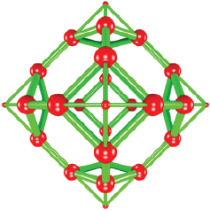
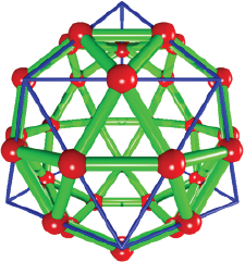
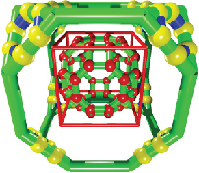
The study of the coordination number in face centered cubic (FCC) gold structures, grant us with the first sight of an Archimedean solid; the cuboctahedron which is formed among 12 first neighbors linked to one central atom (Figure 1a). Second neighbor’s analysis of the gold atoms arrangement (Figure 1b), let us visualize the shape of an octahedron with surrounding atoms located at the cell parameter value (approx. acube = 4.07 Å). Further analysis shows us another fascinating atomic arrangement: a distorted rhombicuboctahedron formed by 24 neighboring atoms, which are located at circa 4.98 Å (acube*sqrt (6)/2 distance value). More recently, it was reported that the thiolated gold clusters can be described using distorted tetrahedron and octahedron building blocks. It attests the distortion induced by the sulfur atoms to the gold-gold bonds with the size reduction on clusters. The polyhedral approach is interesting because it maintains the idea of compactness when it refers to metal clusters (Tlahuice-Flores, 2019).
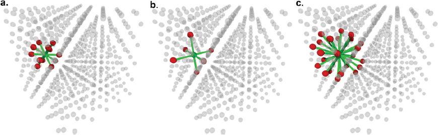
Source: Author’s elaboration.
Figure 1 (a) The nearest 12 neighbors in a metal with FCC structure are displayed. Central atom (in green color) is surrounded by atoms (in red color) describing a cuboctahedron. (b) Second neighbors in FCC structure are forming an octahedral arrangement. (c) The distorted rhombicuboctahedron arrangement of 24 third neighbors are shown. The rest of the atoms forming the FCC structure are displayed in glass texture.
The literature related to geometrical studies of metal clusters included cuboctahedron, icosahedron, body centered cubic and simple cubic structures providing us with formulas to determine the number of constituting atoms, coordination numbers and so on (Montejano-Carrizales, 1997). Recently, some of us have published the study of Au60 cluster modeled as one snub dodecahedron in its neutral charge state. Obtaining degenerated frontier orbitals in accordance with its displayed I-symmetry (Jacobo-Fernández et al., 2021). This example, clearly attests the importance of an orientated to objects code to facilitate the generation of cartesian coordinates of structures with chemical relevance, being this the first step to simulate related structures.
In this article, we describe a project devoted to the study of 13 Archimedean solids carried out by undergraduate students; the used methodology is described, and the obtained results are summarized.
Archimedean solids and their construction
It is important to know that Archimedean solids were named after Archimedes work (287-212 BCE). There are 13 Archimedean solids and they can be constructed from the Platonic solids. Each Archimedean solid is comprised by same type of regular faces sharing common vertices; thus, each vertex is linked to the same type of faces, and it looks similar from a close-up view. Moreover, only Platonic solids containing triangular faces (tetrahedron, icosahedron and octahedron) can produce three of the Archimedean solids by truncation of one third of their edges (truncated icosahedron, truncated octahedron, truncated tetrahedron). In the case of truncation at the middle point of the Platonic solid edges, the icosidodecahedron (starting from the icosahedron/dodecahedron) and the cuboctahedron (from the cube) are generated. The other eight Archimedean solids require correction operations such as translation (truncated cube, truncated cuboctahedron, rhombicuboctahedron, rhombicosidodecahedron, truncated icosidodecahedron, and truncated dodecahedron) (Ball and Coxeter, 1987) and rotation of their faces to produce the same length of their edges (snub cube and snub dodecahedron) (Wells, 1991).
Methodology
We started our study by proposing new algorithms in the Pov-Ray1 language to model the 13 Archimedean solids. Pov-Ray is a powerful tool to code related mathematical algorithms and to generate 3D models (initial configurations). In this opportunity, our programmed truncation algorithms to model Platonic solids were not enough and new algorithms to select, translate and rotate faces were implemented. Such algorithms were used to correct the truncated structures sustaining not equal edge lengths (Table 1). With respect to Pov-Ray codes, the use of macros was mandatory to reduce the repetition of code lines and to reduce the size of related programs. An introductory use of macros is provided in the supporting information with one example. In Table 2 are included geometrical features of 13 Archimedean solids.
Table 1 Description of the used operations to produce the Archimedean solids starting from related either Archimedean or Platonic solids.
| Archimedean solid | From the Archimedean/ Platonic solid |
Operation |
|---|---|---|
| Cuboctahedron | Cube/Octahedron | Truncation of edges in two equal parts |
| Truncated cube | Cuboctahedron Cube |
Perpendicular translation of triangular faces Irregular truncation of square faces |
| Truncated cuboctahedron | Truncated
cube/ Cuboctahedron/ Rhombicuboctahedron |
Truncation of triangular faces and translation/truncation in three equal parts of the triangular faces and translation/ translation outwards of square faces |
| Rhombicuboctahedron | Cube/Octahedron/ Cuboctahedron |
Perpendicular translation of square faces/perpendicular translation of triangular faces/Truncation of edges in two equal parts |
| Snub cube | Rhombicuboctahedron | Rotation of square faces of rhombicuboctahedron |
| Rhombicosidodecahedron | Dodecahedron/ Icosahedron |
Translation of dodecahedron/ icosahedron faces |
| Snub dodecahedron | Rhombicosidodecahedron | Rotation of pentagonal faces of rhombicosidodecahedron |
| Truncated tetrahedron | Tetrahedron | Truncation of edges in three equal parts |
| Truncated octahedron | Octahedron | Truncation of edges in three equal parts |
| Truncated icosahedron | Icosahedron | Truncation of edges in three equal parts |
| Truncated icosidodecahedron | Icosidodecahedron/ Truncated dodecahedron/ Truncated Icosahedron |
Truncation and translation of hexagonal faces/translation of decagons/ translation of hexagonal faces |
| Truncated dodecahedron | Dodecahedron/ Icosidodecahedron |
Irregular truncation and perpendicular translation of triangular faces/ translation of triangular faces |
| Icosidodecahedron | Dodecahedron/ Icosahedron | Truncation of edges in two equal parts |
Source: Author's elaboration.
Table 2 Geometrical features of 13 Archimedean solids.
| Archimedean solid | Type of face | Number of faces |
Number of edges |
Number of vertices |
|---|---|---|---|---|
| Cuboctahedron | 8 triangles; 6 squares | 14 | 24 | 12 |
| Truncated cube | 8 triangles; 6 octagons | 14 | 36 | 24 |
| Truncated cuboctahedron | 12 squares; 8 hexagons; 6 octagons | 26 | 72 | 48 |
| Rhombicuboctahedron | 8 triangles; 18 squares | 26 | 48 | 24 |
| Snub cube | 32 triangles; 6 squares | 38 | 60 | 24 |
| Rhombicosidodecahedron | 20 triangles; 30 squares; 12 pentagons | 62 | 120 | 60 |
| Snub dodecahedron | 80 triangles; 12 pentagons | 92 | 150 | 60 |
| Truncated tetrahedron | 4 triangles; 4 hexagons | 8 | 18 | 12 |
| Truncated octahedron | 6 squares; 8 hexagons | 14 | 36 | 24 |
| Truncated icosahedron | 12 pentagons; 20 hexagons | 32 | 90 | 60 |
| Truncated icosidodecahedron | 30 squares; 20 hexagons; 12 decagons | 62 | 180 | 120 |
| Truncated dodecahedron | 20 triangles; 12 decagons | 32 | 90 | 60 |
| Icosidodecahedron | 20 triangles; 12 pentagons | 32 | 60 | 30 |
Source: Author’s elaboration.
It is important to mention that the truncated octahedron is the unique Archimedean solid whose repetition in the space can fill it with no gaps. In solid state this shape is assumed by the Wigner Seitz cell of FCC structure (Kittel, 1996).
Learning objetives
In this project, second year undergraduate students were devoted to the geometrical study of Archimedean solids and their relationship with Platonic solids. All the obtained models can be considered as part of their training to further study of electronic properties of nanostructures of boron, carbon or gold.
As part of this project, students learnt about translation and rotation operations to generate some of 13 Archimedean solids. They applied their previous knowledge on an object-oriented language with the goal of generate new irregular solids. All the work is oriented to model chemical structures with relevance in areas as materials science. In the process, it was necessary to introduce the use of macros to reduce/adapt the code included in this publication. The effectiveness and compliance of our project goals is corroborated by the final written reports, the discussion of algorithms and the final codes herein delivered.
Conceptual orientation
Operations to generate Archimedean solids
The modeling of various Archimedean solids was based on the implementation of new algorithms to make some operations as:
Selection of regular faces. It implies to find each perpendicular vector to every face of the solid. The use of cross vector/dot product operation among two vectors sharing a vertex and forming a pair of edges was necessary. The centered cube (centered at 0,0,0) is related to various Archimedean solids whose perpendicular vectors are directed along the cube diagonals.
Translation of selected faces. It is obtained by adding a perpendicular vector to each vertex forming a face. For example, this operation produces the perpendicular displacement (k) applied to the square faces of the cube to produce the rhombicuboctahedron.
Rotation of selected faces. It is easily done by using the perpendicular vector to each face and finding numerically the proper rotation angle.
Location of vertices along one edge where no regular truncation is possible. This operation was implemented as a macro and it yields the proportional displacement to truncate the Platonic solids in order to obtain 5 of the 13 Archimedean solids.
It is important to note that various of the parameters used to build the Archimedean solids were calculated numerically, for example, in the case of the rhombicuboctahedron, the calculation of the magnitude of the perpendicular vector (k) to one square face of the cube was done by adding up a fraction of the perpendicular vector to each vertex of the cube and the distance among the translated positions was used to stop the search.
The use of macros in an object-oriented programming language
The use of macros is recommended when there exist lines that are repeated through the code. The syntaxis to declare a macro is defined in the Box 1. Tokens refer to any number of Pov -Ray keywords, or punctuation marks which are the body of the macro. In such manner that it contains the code that is repeated, and it is pretended to replace it. In the supporting information is given an example of a macro.
The algorithm to make an irregular truncation
In Table 2 are found 5 Archimedean solids whose names include the word truncated. Among them, the truncated tetrahedron, truncated octahedron, and truncated icosahedron are obtained by a regular truncation (truncation of one third of their edges) of the related Platonic solids. Conversely, the truncated cube and truncated dodecahedron, cannot be truncated in an easy form and one new algorithm was proposed to make this possible. In the following is explained the algorithm used to truncate 5 Platonic solids and to obtain related Archimedean solids. In addition, in Figure 2 is illustrated the algorithm.
Location of three points P1, P2 and P3 forming a pair of equal edges with a common vertex (P1).
Calculation of a pair of vectors: V1 = P3-P1 and V2 = P2-P1 to define the direction of the displacement.
Two new positions P4 and P5 are created along the V1 vector and one position P6 along the V2 vector. Look at Figure 2a.
Translation of the P4 and P5 positions resulting in TP4 = P1+h*V1 and TP5 = P3- h*V1, being h the magnitude of the displacement.
Translation of the P6 position by using TP6 = P1+h*V2.
Calculation of the distance among translated point TP4 and TP6. When distance among TP6 and TP4 equals the distance among TP4 and TP5, the displacement is known, and it represents the proportion of truncation. See Figure 2b for a final look of the algorithm.
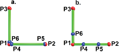
Source: Author’s elaboration.
Figure 2 The illustration of the algorithm used to truncate five Platonic solids and to generate the related Archimedean solids. (a) It starts with three vertices and two edges sharing a common vertex (P1) and placing a pair of new vertices (P5 and P4) along the direction given by the vector P2-P1. The position along the P3-P1 edge is used to conditionate the small displacement applied to P4 and P5 vertices. (b) The correct displacement is reached when the distance among TP6 and TP4 equals the distance in the other edge (TP4-TP5).
The algorithm can be easily implemented for solids with edges forming an angle different of 90º used in Figure 2.
The given algorithm was coded as a macro and in the Box 2 is delivered.
Box 2. Macro for an irregular truncation of Platonic solid edges. It determines the displacement to be applied to vertices forming the truncated Archimedean solids
#macro Found_inc(Angle)
#declare P1=<0,0,0>;
#declare P2=<1,0,0>;
#declare P3=vaxis_rotate(P2,<0,0,1>,Angle);
#declare P4=P1;
#declare P5=P2;
#declare P6=P1;
#declare inc=0.27;
#declare h=0.00001;
#declare Cad=”Au “;
#while (VDist(P4,P5)>VDist(P4,P6))
#declare P4=inc*P2;
#declare P5=(1-inc)*P2;
#declare P6=inc*P3;
#declare inc=inc+h;
#end
#end
Results and discussions
The Archimedean solids can be generated starting from various related polyhedral solids as can be seen in Table 1. In the next section, we discuss about the chosen path and the algorithm; also, we provide the programmed codes of each Archimedean solid.
The truncated tetrahedron from tetrahedron
The truncated tetrahedron consists of 4 hexagons, 4 triangles, 12 vertices and 18 edges. Despite the regular truncation is done by reducing the original tetrahedron edge to one third, we proved the effectiveness of our proposed algorithm by finding the same proportion. See Figure 3 for the structure, and the code is given in Box 3.
Source: Author’s elaboration.
Figure 3 Truncated tetrahedron obtained by using the macro included in Box 2. Thin cylinders correspond with the parent tetrahedron.
Box 3. POV-Ray code to make a truncated cube
// Insert here the last definition of libraries,
// light_source, camera, and background
#declare Pos= array[8]; // Cube positions
#declare TC= array [24]; // Truncated cube vertices
#declare acube=1; // Cube edges length
#declare Pos[0]= <acube/2, acube/2, acube/2>;
#declare Pos[1]= <-acube/2, -acube/2, -acube/2>;
#declare Pos[2]= <-acube/2, acube/2, acube/2>;
#declare Pos[3]= <acube/2, -acube/2, acube/2>;
#declare Pos[4]= <acube/2, acube/2, -acube/2>;
#declare Pos[5]= <-acube/2, -acube/2, acube/2>;
#declare Pos[6]= <-acube/2, acube/2, -acube/2>;
#declare Pos[7]= <acube/2, -acube/2, -acube/2>;
#declare L=acube+0.1;
#fopen CT "TruncatedCube.xyz" write
Found_inc(90)
//Call the macro to know the fraction to truncate the square face.
#declare cont=0;
#declare i=0;
#while(i<7)
#declare j=i+1;
#while (j<8)
#declare Distan=VDist(Pos[i],Pos[j]);
#declare Desp=Pos[j]-Pos[i];
#if(Distan<L;
#declare TC[cont ]=Pos[i]+inc*Desp;
#declare TC[cont+1]=Pos[i]+(1-inc)*Desp;
//There are 2 points in the edge: the closer to Pos[i] and
the closer to Pos[j]
#write (CT,"Au", " ",vstr(3, TC[cont ]," ",3,5),"\n")
#write (CT,"Au", " ",vstr(3, TC[cont+1]," ",3,5),"\n")
sphere{TC[cont],0.2 texture {pigment{color Blue}}}
sphere{TC[cont+1],0.2 texture {pigment{color Blue}}}
#declare cont=cont+2;
#end
#declare j=j+1;
#end
#declare i=i+1;
#end
The truncated cube from cube
The truncated cube has 6 octagons, 8 triangles, 24 vertices and 36 edges. The truncation of cube is not regular, and the proportion of truncation was determined as approx. 0.293 times the cube edge length (Ni et al., 2005). See Figure 4 for the structure of the truncated tetrahedron, and its code is given in Box 4.
Source: Author’s elaboration.
Figure 4 Truncated cube obtained with our proposed macro. Evidently the truncation is not regular, and it was necessary to implement a new algorithm (Box 2).
Box 4. POV-Ray code to make a truncated tetrahedron
// Insert here the last definition of libraries,
// light_source, camera, and background
//Insert here the macro to find the displacement of the
tetrahedron positions
#declare atetra=1; // Tetrahedron edges length
#declare L=atetra*sqrt(2)+0.1;
#declare PosTetra= array[4]; // Tetrahedron positions
#declare TT= array [12]; // Truncated tetrahedron vertices
#declare PosTetra[0] = <atetra/2, atetra/2, atetra/2>;
#declare PosTetra[1] = <-atetra/2, -atetra/2, atetra/2>;
#declare PosTetra[2] = <-atetra/2, atetra/2, -atetra/2>;
#declare PosTetra[3] = <atetra/2, -atetra/2, -atetra/2>;
#fopen TTf "TruncatedTetrahedron.xyz" write
Found_inc(60)
//Call the macro to know the proportion to truncate an
equilateral triangular face.
#declare cont=0;
#declsre i=0;
#while(i<3)
#declare j=i+1;
#while (j<4)
#declare Distan=VDist(PosTetra[i],PosTetra[j]);
#declare Desp=PosTetra[j]-PosTetra[i];
#if(Distan<L$
#declare TT[cont ]=PosTetra[i]+inc*Desp;
#declare TT[cont+1]=PosTetra[i]+(1-inc)*Desp;
//There are 2 points in the edge: the closer to PosTetra[i]
and the closer to PosTetra[j]
#write (TTf,"Au", " ",vstr(3, TT[cont ]," ",3,5),"\n")
#write (TTf,"Au", " ",vstr(3, TT[cont+1]," ",3,5),"\n")
sphere{TT[cont],0.2 texture {pigment{color Blue}}}
sphere{TT[cont+1],0.2 texture {pigment{color Blue}}}
#declare cont=cont+2;
#end
#declare j=j+1;
#end
#declare i=i+1;
#end
The truncated octahedron from octahedron
The regular truncation of an octahedron results in the truncated octahedron. It shows 8 hexagons, and 6 squares; it has 24 vertices and 36 edges. See Box 5 for code, and Figure 5 for the structure.
Source: Author’s elaboration.
Figure 5 Truncated octahedron and its relationship with the octahedron. The truncation of the octahedron produces a truncated octahedron with an edge of one third of the original one.
Box 5. POV-Ray code to make a truncated octahedron
// Insert here the last definition of libraries,
// light_source, camera, and background
//Insert here the macro included in Box 2.
#declare aoct=sqrt(2); // Octahedron edges length
#declare L=aoct*sqrt(2)/2+0.1;
#declare PosOct= array[6]; // Octahedron positions
#declare TO= array [24]; // Truncated tetrahedron vertices
#declare PosOct[0] = <aoct/2, 0, 0>;
#declare PosOct[1] = <-aoct /2, 0, 0>;
#declare PosOct[2] = <0, aoct/2, 0>;
#declare PosOct^j = <0, -aoct/2, 0>;
#declare PosOct[4] = <0, 0, aoct/2>;
#declare PosOct[5] = <0, 0, -aoct/2>;
#fopen TOf "TruncatedOctahedron.xyz" write
Found_inc(60)
//Call the macro to find what fraction we have to translate in
an equilateral triangular face.
#declare cont=0;
#declare i=0;
#while(i<5)
#declare j=i+1;
#while (j<6)
#declare Distan=VDist(PosOct[i],PosOct[j]);
#declare Desp=PosOct[j]-PosOct[i];
#if(Distan<L;
#declare TO[cont ]=PosOct[i]+inc*Desp;
#declare TO[cont+1]=PosOct[i]+(1-inc)*Desp;
//There are 2 points in the edge: the closer to PosOct[i] and
the closer to PosOct[j]
#write (TOf,"Au", " ",vstr(3, TO[cont ]," ",3,5),"\n")
#write (TOf,"Au", " ",vstr(3, TO[cont+1]," ",3,5),"\n")
sphere{TO[cont],0.2 texture {pigment{color Blue}}}
sphere{TO[cont+1],0.2 texture {pigment{color Blue}}}
#declare cont=cont+2;
#end
#declare j=j+1;
#end
#declare i=i+1;
#end
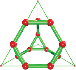
The truncated dodecahedron from dodecahedron
This Archimedean solid is comprised by 12 decagons, 20 triangles, 60 vertices and 90 edges. It can be obtained by an irregular truncation of the dodecahedron to form the decagons and to obtain the triangles. The fraction to truncate the pentagonal faces was calculated as 0.276 times the edge length of the dodecahedron. In Box 6 is provided the code to generate the truncated dodecahedron (Figure 6) based on the macro showed in Box 2.
Source: Author’s elaboration.
Figure 6 Truncated dodecahedron. The thin cylinders feature the edges of the original dodecahedron.
Box 6. POV-Ray code to make a truncated dodecahedron
from dodecahedron
// Insert here the last definition of libraries,
// light_source, camera, and background
//Insert here the macro included in Box 2.
#declare n=20;
#declare dode=array[n]
#declare acube=1;
#declare L=0.7;
#declare fi=(sqrt(5)-1)/2;
// Dodecahedron vertices
#declare dode[0]= (acube/2)*<1+fi,0,fi>;
#declare dode[1]= (acube/2)*<-(1+fi),0,-fi>;
#declare dode[2]= (acube/2)*<1+fi,0,-fi>;
#declare dode[3]= (acube/2)*<-(1+fi),0,fi>;
#declare dode[4]= (acube/2)*<0,fi,1+fi>;
#declare dode[5]= (acube/2)*<0,fi,-(1+fi)>;
#declare dode[6]= (acube/2)*<0,-fi,1+fi>;
#declare dode[7]= (acube/2)*<0,-fi,-(1+fi)>;
#declare dode[8]= (acube/2)*<fi,1+fi,0>;
#declare dode[9]= (acube/2)*<fi,-(1+fi),0>;
#declare dode[10]= (acube/2)*<-fi,1+fi,0>;
#declare dode[11]= (acube/2)*<-fi,-(1+fi),0>;
#declare dode[12]= (acube/2)*<1,
1, 1>;
#declare dode[13]= (acube/2)*<-1, -1, -1>;
#declare dode[14]= (acube/2)*<-1,
1, 1>;
#declare dode[15]= (acube/2)*<1,
-1, 1>;
#declare dode[16]= (acube/2)*<1,
1, -1>;
#declare dode[17]= (acube/2)*<-1, -1, 1>;
#declare dode[18]= (acube/2)*<-1,
1, -1>;
#declare dode[19]= (acube/2)*<1,
-1, -1>;
#fopen DTf “TruncatedDodecahedron.xyz” write
Found_inc(108)
//Call the macro to find the truncation value over the
edges of pentagonal faces.
#declare cont=0;
#declare PosT=array[60];
#declare i=0;
#while(i<n-1)
#declare j=i+1;
#while (j<n)
#declare Distan=VDist(dode[i],dode[j]);
#declare Desp=dode[j]-dode[i];
#if(Distan<L)
#declare PosT[cont]=dode[i]+inc*Desp;
#write (DTf,”Au”, “ “,vstr(3, PosT[cont],” “,3,5),”\n”)
#write (DTf,”Au”, “ “,vstr(3, PosT[cont],” “,3,5),”\n”)
sphere { PosT[cont], 0.1 pigment{color Red} }
#declare cont=cont+1;
#declare PosT[cont]=dode[i]+(1-inc)*Desp;
sphere { PosT[cont], 0.1 pigment{color Red} }
#declare cont=cont+1;
#end
#declare j=j+1;
#end
#declare i=i+1;
#end
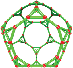
The truncated icosahedron from icosahedron
In Chemistry, this is the most famous Archimedean solid given the fact that C60 molecule was confirmed experimentally (Kroto et al., 1985). Just like the other two Platonic solids previously discussed (tetrahedron and octahedron) the icosahedron is formed only by 20 triangular faces. This means that truncated icosahedron, can be easily obtain by dividing the 30 edges of the icosahedron into three equal parts (two new positions located at each icosahedron edges). The structure of truncated icosahedron is depicted in Figure 7 and the programmed code is given in Box 7.
Source: Author’s elaboration.
Figure 7 Truncated icosahedron. The icosahedron edge is divided among three in such manner that the 30 edges generate the 60 vertices of this Archimedean solid. Thin cylinders represent the icosahedron edges.
Box 7. POV-Ray code to make a truncated icosahedron with length 1
// Insert here the last definition of libraries,
// light_source, camera, and background
#declare ico= array[12];
// Icosahedron positions
#fopen ITf “TruncatedIcosahedron.xyz” write
#declare fi=(sqrt(5)-1)/2;
#declare acube=3/fi;
// Icosahedron coordinates
#declare ico[0]= (acube/2)*<1,0,fi>;
#declare ico[1]= (acube/2)*<-1,0,-fi>;
#declare ico[2]= (acube/2)*<1,0,-fi>;
#declare ico[3]= (acube/2)*<-1,0,fi>;
#declare ico[4]= (acube/2)*<0,fi,1>;
#declare ico[5]= (acube/2)*<0,fi,-1>;
#declare ico[6]= (acube/2)*<0,-fi,1>;
#declare ico[7]= (acube/2)*<0,-fi,-1>;
#declare ico[8]= (acube/2)*<fi,1,0>;
#declare ico[9]= (acube/2)*<fi,-1,0>;
#declare ico[10]= (acube/2)*<-fi,1,0>;
#declare ico[11]= (acube/2)*<-fi,-1,0>;
// This block is to calculate the distances among vertices
// of icosahedron
#declare RIc=0.1;
#declare i=0;
#declare n=12; // vertices of icosahedron
#declare ladoIco=acube*fi;
#declare kC60=1; // counter
#fopen Icotrunc “TruncatedIcosahedron.xyz” write
#declare IcoTrun= array[60];
#while (i<n-1)
#declare j=i+1;
#while (j<n)
#declare IcoDist= VDist(ico[i], ico[j]);
#if( IcoDist<= ladoIco+0.1 )
#declare IcoTrun[kC60]= ico[j];
#declare IcoTrun[kC60 ]= ico[i]+ (ico[j]-ico[i])/3;
#write (ITf,”Au”, “ “,vstr(3, IcoTrun[kC60 ],”
“,3,5),”\n”)
sphere {IcoTrun [kC60], RIc pigment{color Cyan}
finish{phong 1}}
#write (Icotrunc,”Au”, “ “,vstr(3, IcoTrun [kC60 ],”
“,3,5),”\n”)
#declare IcoTrun[kC60]= ico[i]+ 2*(ico[j]-
ico[i])/3;
sphere { IcoTrun [kC60], RIc pigment {color
Cyan} finish{phong 1}}
#write (Icotrunc,”Au”, “ “,vstr(3, IcoTrun [kC60],”
“,3,5),”\n”)
#declare kC60=kC60+1;
#end
#declare j=j+1;
#end
#declare i=i+1;
#end
The cuboctahedron from a cube
It has 8 triangular and 6 square faces with 12 vertices. It is obtained by dividing the cube edges (acube = 1) in two halves. The position vectors of the cube vertices are perpendicular to the triangular faces while the unitary i, j, and k vectors are perpendicular to its square faces. The edge length of cuboctahedron equals sqrt (2)/2. Figure 8 shows the cuboctahedron and its relationship with the cube.
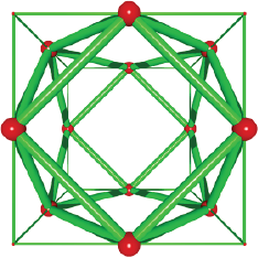
Source: Author’s elaboration.
Figure 8 A cuboctahedron obtained by truncation of the cube edges. The cuboctahedron edges have a length of sqrt (2)/2. The thin cylinders feature the parent cube.
The algorithm to truncate the cube edges in two halves is given by the formula 1, which is used to obtain the positions of the cuboctahedron. Box 8 contains the programmed code to obtain the cuboctahedron from the cube and it implies to calculate the middle point among a pair of vertices separated by the length of the cube (acube).
Box 8. POV-Ray code to make a cuboctahedron
// Insert here the last definition of libraries,
// light_source, camera, and background
#declare acube=2/sqrt(2);
//cube edges length
#declare Pos= array[8];
// cube positions
#declare cuboc= array [12]; // cuboctahedron vertices
// Cube positions (Box 3)
#fopen cuboct “cuboctahedron.xyz” write
// This block is to calculate the distances among vertices
// and to define edges
//Calculating the center of cube edges
#declare i=0;
#declare ncub=0;
#declare n=8;
#while (i<n-1)
#declare j=i+1;
#while (j<n)
#declare L= VDist(Pos[i],Pos[j]);
#if(L< acube+0.1)
#declare cuboc[ncub]=Pos[i]+0.5*(Pos[j]- Pos[i]);
sphere{cuboc[ncub], 0.25 pigment{color Red}}
#write (cuboct,”Au”, “ “,vstr(3, cuboc[ncub],” “,3,5),”\n”)
#declare ncub=ncub+1;
#end
#declare j=j+1;
#end
#declare i=i+1;
#end
The icosidodecahedron from the icosahedron
This solid has 32 faces, 20 of them are triangles and 12 are pentagons. It has 30 vertices and 60 edges (Figure 9). Just like the cuboctahedron, which can be obtain both from the cube or its dual (the octahedron) the icosidodecahedron can be obtain by locating a vertex in the middle point of the edges of either the dodecahedron or its dual. In other words, the icosidodecahedron is obtained by regular truncation of the icosahedron edges. In such manner that we can reuse the code to obtain the cuboctahedron. However, the initial vertices, will form the icosahedron instead of a cube. Evidently, formula 1 is also applied to this code (see Box 9).
Source: Author’s elaboration.
Figure 9 Icosidodecahedron. It was obtained by finding the middle point of the icosahedron edges. The thin and blue sticks correspond with the icosahedron.
Box 9. POV-Ray code to make an icosidodecahedron
// Insert here the last definition of libraries,
// light_source, camera, and background
#declare ico= array[12];
// Icosahedron positions
#declare icosi= array [30]; // Icosidodecahedron vertices
#declare fi=(sqrt(5)-1)/2;
#declare acube=1*fi; //Icosahedron edges
#fopen Icf “Icosidodecahedron.xyz” write
// Icosahedron coordinates
#declare ico[0]= (acube/2)*<1,0,fi>;
#declare ico[1]= (acube/2)*<-1,0,-fi>;
#declare ico[2]= (acube/2)*<1,0,-fi>;
#declare ico[3]= (acube/2)*<-1,0,fi>;
#declare ico[4]= (acube/2)*<0,fi,1>;
#declare ico[5]= (acube/2)*<0,fi,-1>;
#declare ico[6]= (acube/2)*<0,-fi,1>;
#declare ico[7]= (acube/2)*<0,-fi,-1>;
#declare ico[8]= (acube/2)*<fi,1,0>;
#declare ico[9]= (acube/2)*<fi,-1,0>;
#declare ico[10]= (acube/2)*<-fi,1,0>;
#declare ico[11]= (acube/2)*<-fi,-1,0>;
#declare ladoIco=acube*fi;
// This block is to calculate the distances among vertices
// and to define edges
//Calculating the middle point of icosahedron edges
#declare i=0;
#declare nicos=0;
#declare n=12;
#while (i<n-1)
#declare j=i+1;
#while (j<n)
#declare L= VDist(ico[i],ico[j]);
#if(L< ladoIco+0.1)
#declare icosi[nicos]=ico[i]+0.5*(ico[j]- ico[i]);
#write (Icf,”Au”, “ “,vstr(3, icosi[nicos],” “,3,5),”\n”)
sphere{icosi[nicos], 0.25 pigment{color Red}}
#declare nicos=nicos+1;
#end
#declare j=j+1;
#end
#declare i=i+1;
#end
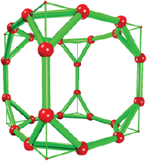
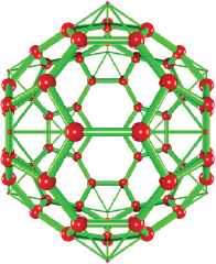
The truncated icosidodecahedron from the truncated icosahedron
It is also known as great rhombicosidodecahedron and it is the largest Archimedean solid. The structure is built by 30 squares, 20 hexagons and 12 decagons. It has 120 vertices and 180 edges. It can be constructed by dividing the icosidodecahedron edges in three equal parts and a further translation along a perpendicular vector of the formed hexagons (i.e., related dodecahedron vertices). However, we chosen to start from a truncated icosahedron (Figure 7), whose hexagonal faces were translated along the dodecahedron vertices. The selection of hexagonal faces implies to calculate the dot product among the face vertices and its perpendicular vector. It was determined that a value of circa 0.875 (i.e., k = 0.875) for the dot product allows to select the hexagonal faces. The translation vector k was calculated as circa 1.40 times the hexagon edge (Williams, 1979). The described algorithm is given in terms of formulas 2 and 3. See Figure S1(Annex) for more geometrical details.
Where
Formula 3 stands for the
translation of the obtained hexagonal faces
In Box 10 the programmed code is included, and it contains in the last part the algorithm to select and translate vertices. The structure is displayed in Figure 10.
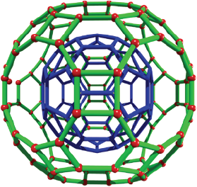
Source: Author’s elaboration.
Figure 10 Truncated icosidodecahedron or great rhombicosidodecahedron. The hexagonal faces of the truncated icosahedron are translated along perpendicular vectors, it means along the dodecahedron vertices. The truncated icosahedron is displayed in blue color.
Box 10. POV-Ray code to make a truncated icosidodecahe-
dron from a truncated icosahedron
// Insert here the last definition of libraries,
// light_source, camera, and background
// icoTrun array contains the Truncated icosahedron vertices
// Calculation of the vertices of dual of the icosahedron
// Copy here Box 9
#declare n=12;
#declare conter=0;
#declare i = 0;
#while ( i < n-1)
#declare j = i + 1;
#while ( j < n)
#declare k = j + 1;
#while ( k < n)
#declare L1= VDist(ico[i], ico[j]);
#declare L2= VDist(ico[i], ico[k]);
#declare Angulo= VAngleD( ico[j]-ico[i], ico[k]-ico[i]);
// Angle formed among edges
#if (L1=a & L2=a & Angulo=60)
#declare dode[conter]= (ico[i]+ico[j]+ico[k])/3;
#declare conter=conter+1;
#end
#declare k= k + 1;
#end
#declare j= j + 1;
#end
#declare i= i + 1;
#end
#fopen out3 “seleccion2.dat” write
#fopen out5 “TruncatedIcosidodecahedron.xyz” write
// Selection and Translation of hexagonal faces
#declare counter1=0;
#declare i=0;
#while(i<60)
#declare j=0;
#while (j<20)
// vdot is 0.8710180527 for hexagons and their perpendicular
vectors
#if ( vdot( icoTrun[i] , dode[j] ) < (0.89) & vdot( icoTrun[i] ,
dode[j] )>(0.84) )
#declare icosit[counter1]=icoTrun[i]
+1.4011*a/3*vnormalize(dode[j]);
#write(out3, icosit[counter1], “\n”)
#write(out5,”Au”, “ “,vstr(3,icosit[counter1], “ “,3,5),”\n”)
sphere { icosit[counter1], 0.05 pigment{color Red} finish {phong
1}}
#declare counter1=counter1+1;
#end
#declare j=j+1;
#end
#declare i=i+1;
#end
//Truncated icosidodecahedron model
#declare i=0;
#while(i<118)
#declare j=i+1;
#while(j<119)
#declare dist6=VDist(icosit[i],icosit[j]);
#if (dist6<0.5 & dist6>0.3)
cylinder{ icosit[i] icosit[j] 0.03 pigment{color Green}}
#end
#declare j=j+1;
#end
#declare i=i+1;
#end
The rhombicuboctahedron from a cube
The rhombicuboctahedron is constituted by 18 square faces, 8 triangular faces and 24 vertices, being the same edge length in both type of faces. It is an Archimedean solid formed by the outward translation of the vertices forming each square face of a cube. The translation of each square face is along its respective perpendicular vectors (they can be calculated using the formula 4). In the case of one centered cube with an edge of acube, <acube/2,0,0>, <-acube/2,0,0>, <0,acube/2,0>, <0,-acube/2,0>, <0,0,acube/2> and <0,0,-acube/2> represent perpendicular vectors to each square face. The magnitude of the perpendicular vectors can be analytically calculated and it corresponds with the acube/sqrt(2) value (i.e. k = 0.7071*acube in formula 5). We calculate numerically the k value by adding up successively a fraction of a pair of perpendicular vectors (for example <1,0,0> and <0,0,-1>) to the same cube vertex and attesting that at certain translation, the distance among new created positions equals the cube edge. See supporting information (Figure S1 in Annex) for more details and the used code.
Where
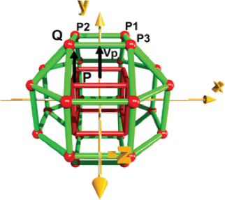
Source: Author’s elaboration.
Figure 11 Rhombicuboctahedron obtained from a cube. All vertices of cube are translated along a perpendicular vector (Vp). Q position is obtained from translation of P position. The triangular faces are formed after the translation of the square faces of the parent cube (red color).
It is also worth to notice that rhombicuboctahedron can also be obtain from the dual of a cube, i.e., the octahedron. The triangular octahedron’s faces must be translated b*0.8660. Being b the length of the octahedron’s edge (b = acube/sqrt(2), and acube the edge of the cube where the octahedron is inscribed). On the other hand, an angle of circa 1.23 radians is comprised between both perpendicular translation vectors, which originate from the octahedron’s vertices. And the angle between the perpendicular vector and the octahedron’s edge is of 0.9547 radians. The same proportion is found when we try to obtain the truncated cube from the cuboctahedron. A full deduction of this is included in the supporting information (Figure S3 in Annex).
The code given in Box 11 can be simplified by using the function Vperp_ To_Plane (V1, V2) where V1 and V2 are along the edges of the polyhedral face. This operation is given by the formula 4. However, we considered important to provide the readers with code that is easy to visualize and to be related to the above given formulas 4 and 5.
The truncated cube from a cuboctahedron
In addition to the irregular truncation of the cube edge (Box 3), in this section is explained another form to truncate the cube. The truncated cube is built by 8 triangular and 6 octagonal faces, linking 24 vertices. It can be obtained by the selection and the outward translation of the triangular faces of the cuboctahedron. This operation is simplified by knowing that position vector of each cube’s vertex is perpendicular to triangular faces of the cuboctahedron. The procedure to translate each triangular face of the cuboctahedron is given in formula 6, where three vertices of the truncated cube are obtained by adding one position vector of the cube to three vertices of the cuboctahedron. This operation is repeated to translate outward all 8 triangular faces constituting the cuboctahedron. The magnitude of perpendicular translation (k vector magnitude) was numerically calculated and it is defined as acube*sqrt(3)/2 (i.e,. acube*0.8660). Figure 12 includes the discussed structure of the truncated cube, and Box 12 has the implemented code.
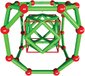
Source: Author’s elaboration.
Figure 12 Making a truncated cube from a cuboctahedron. Each triangular face of the cuboctahedron is translated along one diagonal of the cube. The translated vertices constituting the truncated cube are linked by cylinders featured in green color. Thin red cylinders correspond with the cube.
Box 11. POV-Ray code to make a rhombicuboctahedron
with edge of 1
// Insert here the last definition of libraries, // light_
source, camera, and background
#declare acube=1;
// cube edges length
#declare Pos= array[8];
// cube positions
#declare Rho= array [24];
// Rhombicuboctahedron
vertices
// Insert here cube positions given as (±acube/2, ± acube/2,
± acube/2)
// Calculation of center of cube faces (perpendicular
// vectors)
#declare i=0;
#declare Center=array[6];
#declare counter=0;
#declare n=8;
#declare j=1;
#while (j<n)
#declare L= VDist(Pos[0],Pos[j]);
#if(L=acube*sqrt(2) )
#declare Center[counter]= Pos[0]+(Pos[j]-Pos[0])/2;
#declare Center[counter+1]= -1*Center[counter];
#declare counter=counter+2;
#end
#declare j=j+1;
#end
//selecting vertices to translate on each square face
#declare i=0;
#declare lado= acube*sqrt(2)/2;
#declare coun=0
#while (i<counter)
#declare j=0;
#while (j<n)
#if(VDist(Center[i],Pos[j])= lado)
#declare Rho[coun]=Pos[j];
#declare coun=coun+1;
#end
#declare j=j+1;
#end
#declare i=i+1;
#end
//Translation of square faces
#fopen out “Rhombicuboctahedron.xyz” write
#declare i=0;
#declare n=24;
#while(i<n)
#declare Rho[i]=Rho[i]+ 0.7071*acube
*vnormalize((Center[i/4]));
#declare Rho[i+1]=Rho[i+1]+0.7071*acube
*vnormalize((Center[i/4]));
#declare Rho[i+2]=Rho[i+2]+0.7071*acube
*vnormalize((Center[i/4]));
#declare Rho[i+3]=Rho[i+3]+0.7071*acube
*vnormalize((Center[i/4]));
#write (out,”Au”, “ “,vstr(3,Rho[i], “ “,3,5),”\n”)
#write (out,”Au”, “ “,vstr(3,Rho[i+1], “ “,3,5),”\n”)
#write (out,”Au”, “ “,vstr(3,Rho[i+2], “ “,3,5),”\n”)
#write (out,”Au”, “ “,vstr(3,Rho[i+3], “ “,3,5),”\n”)
#declare i= i+4;
#end
// Drawing the model with spheres
#declare h=pow(10,-3);
#declare i=0;
#while (i<n-1)
sphere {Rho[i],0.2 texture { pigment { color Red} } }
#declare j=i+1;
#while(j<n)
#if (VDist(Rho[i],Rho[j])<acube+2*h &
VDist(Rho[i],Rho[j])>acube-2*h )
cylinder {Rho[i], Rho[j], 0.1 texture {pigment { color
Yellow } } }
#end
#declare j=j+1;
#end
#declare i=i+1;
#end
Box 12. POV-Ray code to make a truncated cube
// Insert here the last definition of libraries,
// light_source, camera, and background
#declare acube=1;
// cube edges length
#declare Pos= array[8];
// cube positions
#declare cuboc= array [12];
// Cuboctahedron vertices
// Insert here cuboctahedron code given in Box 8
#fopen out “truncatedcube.xyz” write
// Selecting triangular faces using the distance to the
center of faces
#declare i=0;
#declare nsele=0;
#declare TC= array [24]; // selected cuboctahedron vertices
#while (i<8)
#declare j=0;
#while (j<ncub)
#if( VDist(Pos[i],cuboc[j]) < sqrt(2)/2 )
#declare TC[nsele]=cuboc[j];
#declare nsele=nsele+1;
#end
#declare j=j+1;
#end
#declare i=i+1;
#end#declare nsele=0;
#declare lado= sqrt(2)/2;
#declare TC= array [24]; //selected cuboctahedron vertices
#while (i<ncen)
#declare j=0;
#while (j<ncub)
#if( VDist(Pos[i],cuboc[j]) < lado )
#declare TC[nsele]=cuboc[j];
#end
#declare i=i+1;
#end
//Translation of triangular faces
#declare i=0;
#while(i<nsele)
#declare TC[i ]=TC[i]+ 0.8660*(sqrt(2)/2)
*vnormalize((Pos[i/3]));
#declare TC[i+1]=TC[i+1]+0.8660*(sqrt(2)/2)
*vnormalize((Pos[i/3]));
#declare TC[i+2]=TC[i+2]+0.8660*(sqrt(2)/2)
*vnormalize((Pos[i/3]));
#write (out,”Au”, “ “,vstr(3,TC[i], “ “,3,5),”\n”)
#write (out,”Au”, “ “,vstr(3,TC[i+1], “ “,3,5),”\n”)
#write (out,”Au”, “ “,vstr(3,TC[i+2], “ “,3,5),”\n”)
#declare i=i+3;
#end
// Final model
#declare h=pow(10,-3);
#declare i=0;
#while (i<nsele-1)
sphere {TC[i],0.2 texture {pigment { color Red} } }
#declare j=i+1 ;
#while(j<nsele)
#if (VDist(TC[i],TC[j])<(sqrt(2)/2)+2*h &
VDist(TC[i],TC[j])>(sqrt(2)/2)-2*h )
cylinder {TC[i],TC[j], 0.1 texture { pigment { color
Yellow} } }
#end
#declare j=j+1;
#end
#declare i=i+1;
#end
The truncated cuboctahedron from a truncated cube
It is also named as great rhombicuboctahedron (Williams, 1979), and it is constituted by 12 square faces, 8 hexagonal faces, 6 octagonal faces and 48 vertices (Figure 13). It can be built by the truncation of triangular faces of the truncated cube in three equal parts to generate the hexagonal faces (formulas 2 and 3). However, further inward translation of hexagons along the perpendicular vectors (cube vertices is necessary to obtain a truncated cuboctahedron with equal edges. The algorithm to construct this Archimedean solid includes a conditional to verify that the edges of the hexagonal faces (one third of the cuboctahedron) equal the distance among neighboring hexagonal faces. In formula 9, the perpendicular vector has a magnitude 0.985 times the edge of the cuboctahedron, and the sign indicates an in-ward translation. Moreover, each perpendicular vector to one hexagonal face is along the position vector of respective cube vertices. See Box 13 for the code.
Source: Author’s elaboration.
Figure 13 Truncated cuboctahedron from a truncated cube. The triangular faces of the truncated cube are truncated in three equal parts and the new hexagonal faces (orange/red sticks) are translated along vectors oriented on the diagonal of the cube indicated in red color. The translated vertices constituting the truncated cuboctahedron are linked by cylinders in orange color.
Box 13. Pov-Ray Code To Make a Truncated Cuboctahedron
// Insert here the last definition of libraries,
// light_source, camera, and background
#declare acube=1;
// cube edges length
#declare Pos= array[8];
// cube positions
#declare cuboc= array [12];
// Cuboctahedron vertices
// Insert here code to make the truncated cube included in Box 12.
TC[24] represents the positions of truncated cube.
#declare hexa1= array [48];
#declare kon=0;
#declare i=0;
#while (i<nsele)
#declare j=i+1;
#while (j<nsele)
#declare V1= TC[j]-TC[i];
#declare k=j+1;
#while (k<nsele)
#declare V2= TC [k]-TC[i];
#declare Dd= VDist(TC [i],TC[j]);
#declare Dd1= VDist(TC [i],TC[k]);
#declare angulo= VAngleD(V1,V2);
//finding edges with a common vertex; edge equals sqrt(2)/2
#if( (Dd<0.8 & Dd>0.7) & (Dd1<0.8 & Dd1> 0.7) &
(angulo>59 & angulo<61))
#declare hexa1[kon ]= TC[i]+ (TC[j]-TC[i])/3;
#declare hexa1[kon+1]=TC[i]+2*(TC[j]-TC[i])/3;
#declare hexa1[kon+2 ]=TC[i]+ (TC[k]-TC[i])/3;
#declare hexa1[kon+3]= TC[i]+2*(TC[k]-TC[i])/3;
#declare hexa1[kon+4 ]=TC[j]+ (TC[k]-TC[j])/3;
#declare hexa1[kon+5]= TC[j]+ 2*(TC[k]-TC[j])/3;
#declare kon=kon+6;
#end
#declare k=k+1;
#end
#declare j=j+1;
#end
#declare i=i+1;
#end
//Selection of hexagons and normal vectors to translate them
#declare Thex= array[480];
#declare ladoCuboc= acube*sqrt(2)/2; //Cuboctahedron edge
#fopen TrCubocta “Truncated-cuboc.xyz” write
#declare konter=1;
#declare i=0;
#while(i<48)
#declare j=0;
#while (j<8)
#if ( vdot(hexa1[i],Pos[j])<(1+0.2) & vdot(hexa1[i], Pos[j] )>
(1-0.2))
#declare Thex[konter]=hexa1[i]-0.985* ladoCuboc
*vnormalize((Pos[j]));
sphere {Thex[konter], 0.3 pigment {rgb <1,0,0>} }
#write (TrCubocta,”H”, “ “,vstr(3, Thex[konter ],” “,3,5),”\n”)
#declare konter=konter+1;
#end
#declare j=j+1;
#end
#declare i=i+1;
#end
The snub cube from the rhombicuboctahedron
This Archimedean solid is comprised by 6 squares, and 32 equilateral triangles. It has 24 vertices and 60 edges. The rotation of the square faces of the rhombicuboctahedron is included in the algorithm given in Box 14. Depending on the rotation (clockwise or counter-clockwise) a pair of enantiomers are produced (it is a chiral structure) (Ball and Coxeter, 1987). If a rotation of circa 16 degrees is applied on each square face, then the square faces of the rhombicuboctahedron seem to rotate in contrary directions when they are seen perpendicular to those square faces. In Figure 14, the structure of the snub cube is provided.
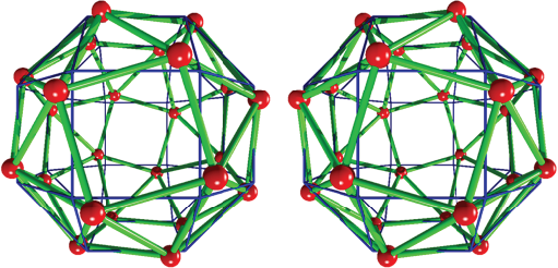
Source: Author’s elaboration.
Figure 14 Snub cube from a rhombicuboctahedron. The square faces of the rhombicuboctahedron (blue color) are rotated with respect to perpendicular vectors passing through the cube faces. The rotated vertices constituting the snub cube are linked by cylinders (green color). Left structure corresponds with a counter-clockwise rotation. Both enantiomers are related by a mirror symmetry operation.
Box 14. POV-Ray code to make a snub cube with edge length of 1
// Insert here the last definition of libraries,
// light_source, camera, and background
#declare acube=1;
// cube edges length
#declare Pos= array[8];
// cube positions
#declare cuboc= array [12];
// Cuboctahedron vertices
// Insert here the rhombicuboctahedron included in Box 11.
Center[counter] represents the center of cube faces. Rho
is the array containing 24 vertices of
rhombicuboctahedron
// Selection of square faces and their rotation
#write (SnubCub,”24”,”\n”)
#write (SnubCub,””,”\n”)
#declare konter3=0;
#declare angulo= 16.47 ;
#declare i=0;
#while(i<24) // vertices
#declare j=0;
#while (j<6) // centers
#if ( vdot(Rho[i],Center[j])<(0.6036+0.1) & vdot(Rho[i],
Center[j] )> (0.6036-0.1) )
#declare Snubcu[konter3]= vaxis_rotate(Rho[i], Center[j],
angulo) ;
sphere {Snubcu[konter3], 0.1 pigment {color Blue} }
#write (SnubCub,”Au”, “ “,vstr(3, Snubcu[konter3 ],”
“,3,5),”\n”)
#declare konter3=konter3+1;
#end
#declare j=j+1;
#end
#declare i=i+1;
#end
It is important to note that we are using the dot product to select square faces of the rhombicuboctahedron. Rotations are carried out by using the command axis_rotate (V1, V2, angle), being V1 the rhombicuboctahedron vertices array and V2 the centers array. The twist angle was determined numerically, and it is of circa 16.47º (WolframMathworld, http://mathworld.wolfram.com/SnubCube.html). On the other hand, the calculated dot product among the perpendicular vector and one vertex of the rhombicosidodecahedron was calculated as 0.6036*acube2. This value is included in our algorithm to select vertices forming a square face and to rotate them with respect to the related perpendicular vector.
The rhombicosidodecahedron from the dodecahedron
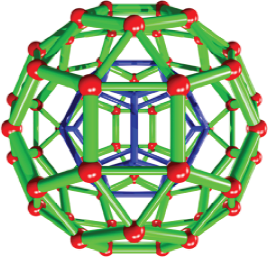
This structure has been found comprising the structure of oneI-Au 144 cluster, and it represents a distorted 60-shell atoms where the gold atoms are separated and they are linked to an inner gold core (Tlahuice-Flores et al., 2013). The rhombicosidodecahedron is an Archimedean solid built by 20 triangles, 30 squares and 12 pentagons. It has 60 vertices and 120 edges. To generate it, we selected each pentagonal face of dodecahedron (12 pentagonal faces) and translated it outwards along a perpendicular vector. The perpendicular vectors are given by the dual of dodecahedron (icosahedron) and their magnitude was calculated as circa 0.951 times the dodecahedron edge length. See Figure 15 for an illustration of the structure and Box 15 for the code.
The snub dodecahedron from the rhombicosidodecahedron
The snub dodecahedron is also known as snub icosidodecahedron. It has 12 pentagons, and 80 equilateral triangles, and its 150 edges join the 60 vertices constituting him. It can be obtained from the rotation of the pentagonal faces of the rhombicosidodecahedron in a similar way that the snub cube is made from the rhombicuboctahedron. The rotation of the pentagonal faces can be done both clockwise and counter-clockwise orientation, resulting in two structures related by a mirror symmetry operation. If the edge of this solid is the unit, then a rotation of 18.2158º is necessary to change the square faces by triangular ones (Weisstein, 2020; WolframMathworld, http://mathworld.wolfram.com/SnubDodecahedron.html). Recently, we have calculated one hollows Au60 cluster corresponding with a perfect snub dodecahedron. It means that modeling of Archimedean can be used to investigate structures with relevance in chemistry (Jacobo-Fernández and Tlahuice-Flores, 2021).
Box 15. Pov-Ray code to make a rhombicosidodecahedron
with edge length of 1
// Insert here the last definition of libraries,
// light_source, camera, and background
#declare acube=1;
// cube edges length
#declare Pos= array[8];
// cube positions
#declare cuboc= array [12]; // Cuboctahedron vertices
// Insert here the dodecahedron and icosahedron arrays.
#declare adode= 1 ;
// dode[n] contains dodecahedron vertices
// Selecting and moving pentagonal faces
#fopen rhombicosidode “rhombicosidodecaedro.xyz” write
#write (rhombicosidode,”60”,”\n”)
#write (rhombicosidode,””,”\n”)
#declare konter=0;
#declare i=0;
#while(i<20)
#declare j=0;
#while (j<12)
#if ( vdot( vnormalize(dode[i]), vnormalize(ico[j]))> (0.75) &
vdot(vnormalize(dode[i]), vnormalize(ico[j] ))< (1.0))
// dot product among one vertex and the center of one
face
#declare Rho[konter]=dode[i]+ 0.95088*adode
*vnormalize((ico[j])); // magnitude of the perpendicular
vector
sphere {Rho[konter], 0.3 pigment {rgb <1,0,0>} }
#write (rhombicosidode,”Au”, “ “,vstr(3, Rho[konter ],”
“,3,5),”\n”)
#declare konter=konter+1;
#end
#declare j=j+1;
#end
#declare i=i+1;
#end
// spheres Model
#declare h=0.1;
#declare i=0;
#while (i<60)
sphere {Rhom[i],0.1 texture { pigment { color Red} } }
#declare j=i+1 ;
#while(j<60)
#if (VDist(Rhom[i],Rhom[j])<adode+2*h &
VDist(Rhom[i],Rhom[j])>adode-2*h )
cylinder {Rhom[i],Rhom[j], 0.05 texture { pigment { color
Yellow} finish { phong 0.0 reflection{ 0.00 metallic
0.00} } } }
#end
#declare j=j+1;
#end
#declare i=i+1;
#end
Figure 16 contains the rhombicosidodecahedron structure. Box 16 contains the Pov-Ray code of the snub dodecahedron.
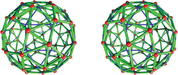
Source: Author’s elaboration.
Figure 16 Snub dodecahedron from the rhombicosidodecahedron. Making a snub dodecahedron from rotation of pentagonal faces of the rhombicosidodecahedron. The cylinders in blue correspond with the rhombicosidodecahedron. The rotation of pentagonal faces transforms the square in triangular faces (green color). To simplify the view, the edges of rhombicosidodecahedron are displayed as thin cylinders.
Box 16. Pov-Ray code to make snub dodecahedron with
p.xyz” write
#declare SnubRho= array [120];
#write (SnubD,”60”,”\n”)
#write (SnubD,””,”\n”)
#declare konter5=0;
#declare angulo=18.215828464309;
#declare i=0;
#while(i<60) // vertices
#declare j=0;
#while (j<12) // centers
#if ( vdot( vnormalize(Rhom[i]),
vnormalize(ico[j]))> (0.75) &
vdot(vnormalize(Rhom[i]), vnormalize(ico[j] ))< (1))
#declare SnubRho[konter5]=
vaxis_rotate(Rhom[i], ico[j], angulo) ;
sphere {SnubRho[konter5], 0.06 pigment {color
Blue} }
#write (SnubD,”Au”, “ “,vstr(3, SnubRho[konter5 ],”
“,3,5),”\n”)
#declare konter5=konter5+1;
#end
#declare j=j+1;
#end
#declare i=i+1;
#end
#declare n=0;
#declare j=0;
// spheres Model
#declare h=0.2;
#declare i=0;
#while (i<60)
#declare j=i+1;
#while(j<60)
#if (VDist(SnubRho[i],SnubRho[j])<adode+2*h &
VDist(SnubRho[i],SnubRho[j])>adode-2*h )
cylinder {SnubRho[i],SnubRho[j], 0.05 texture { pigment
{color Green} finish {phong 0.0
reflection{ 0.00 metallic 0.00} } } }
#end
#declare j=j+1;
#end
#declare i=i+1;
#end
Conclusions
The addressed project was carried out by undergraduate students, and it included the planning, and election of the shortest paths to code the 13 Archimedean solids. This study represents an improvement in their programming level where the use of macros was mandatory to reduce the size of the delivered code. The students were involved in the study of the geometrical relationships of regular and irregular solids, and these let us obtain a more intuitive view during the modeling/construction of the irregular solids. We do not demerit the use of plastic models, but that approach is limited in the size of studied compounds.
Among all proposed/coded algorithms included in this publication, the irregular truncation of edges of a regular solid, let us obtain 3 of the 13 Archimedean solids. However, other algorithms to select faces, to translate and to rotate them were necessary. This resulted in the generation of new algorithms that were coded in an object-oriented language (Pov-Ray).
Regarding the granted capabilities of students, this project improved their spatial depth and requested of their creativity. They were involved during the decision-making process to reach the final goal: the programming of 13 Archimedean solids.

