


 text new page (beta)
 English (pdf)
 Article in xml format
 Article references
 Send this article by e-mail
 Cited by SciELO
  Similars in
SciELO
Similars in
SciELO 
 Permalink
1. INTRODUCTION
Drum and disc brakes are the heart of braking system in automobiles. The working principie is same but they differ in their mechanism. A drum brake is attached concentric to the axle hub having infernal shoe with friction material on it. The compression and expansión of spring actúate the shoes against rotating drum. A disc brake is mounted on the wheel hub with caliper on it. The caliper is mounted on stationary part like stub axle. Actuation of pads against rotating disc may be hydraulic or pneumatic. Disc brakes are more efficient than drum brakes because the heat dissipation from disc is more as it is directly exposed to the environment. In addition to this, friction pads are not subjected to any sort of bending. In case of disc brakes, the contact oceurs equally when pressed against the rotating disc, whereas for drum brakes contact área between pads and drum increases gradually which results in less efficient braking.
During the braking action, kinetic energy of the vehicle is converted into heat due to frictional contact between the pads and disc. The heat dissipation from the front disc brakes is about 70% of the total content of kinetic energy (Muthuvel, Prakash, & Louis, 2015). The objective this paper is to identify the perfect combination of brake disc material on account of different arrangements of cut patterns. Prolonged and continuous braking results in loss of braking efficiency due to excessive temperature in contact área (Talati, & Jalalifar, 2009). So it is important to understand the thermal performance of brake disc under such conditions.
The main problem regarding hard braking is very large amount of heat flux is generated within short amount of time which causes fall in the coefficient of friction. The heat released during braking increases the temperature ranging from 300°; C to 800°; C. The thermal conductivity of pad must be less than that of disc as the heat dissipation is predominantly due to the plástic micro deformation generated due to the frictional forcé (Belhocine, & Bouchetara, 2012). Continuous stress formation may lower the fatigue life of disc and even result into a catastrophic failure (Zhu, Peng, Shi, & Chen, 2009). So in order to avoid such undesirable conditions, brake discs are provided with slots of different patterns to make sure that the holes créate turbulence when disc rotate so as to increase the convective heat transfer to the atmosphere (Pevec, Lerher, Potrc, & Vranesevic, 2010). While designing a brake disc necessary care must be taken that there must be a proper balance between the number of holes to be punched on a disc to its strength to withstand the braking forcé. Henee designing a brake disc is quite difficult task as it is important to optimize the weight and strength of discs with efficient rate of heat transfer from it which may lead to the collision of two design requirements (Jiang, L., Jiang, Y., Liang, Nan, & Ding. 2012). So in this paper an honest attempt is made to satisfy both the requirements in designing of brake disc.
According to literature review, Belhocine (2012), studied thermo-mechanical behavior between brake disc and pad considering dry contact. His main intention was to identify the factors necessary for the geometric design of ventilated disc based on transient temperature conditions. He preferred using grey cast iron due to its good thermo-physical properties. Braking time was assumed as 3.5 sec. He concluded that, the variations in temperature observed were less compared to solid conventional disc. Further he proved that, the ventilation in disc plays an important role as it provides good high temperature thermal resistance. emphasized on using carbón ceramic matrix disc brakes. He performed static structural analysis on composite disc and analyzed its performance with a standard steel disc. The deformation of composite structure was much less than steel. C. Radhakrishnan, Yokeswaran, Naveen Kumar, et al. (2015), focused on use of Titanium alloy 550 brake disc. The reason behind choosing Titanium alloy 550 is because of its thermal stability, high strength and forgeable qualities. The results of this analysis concluded that, the deformation of Titanium alloy 550 was very less compared to cast iron and stresses induced in Titanium alloy 550 were six times less than that of grey cast iron. Shinde, Sagar, & Baskar (2014), worked on cooling performance of disc brake by varying the cut patterns. After performing static structural and thermal analysis, he concluded that elliptical type disc has better heat transfer than circular type. But the strength to withstand the braking forcé was more in case of circular type. Huang, & Chen (2006), calculated heat transfer coefficient of disc brake surface and its effect on design parameters. Making use of Reynold's equation they calculated heat transfer coefficient and from that they calculated amount of flux generated. They tabulated results of heat transfer coefficients depending on operating speeds and temperature. It was observed that, temperature distribution patterns were different for different models. The results obtained were acceptable. Further, they concluded that the model can be used as a design tool for designing brake discs.
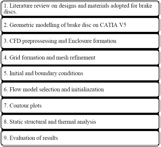
2. METHODOLOGY
Figure 1 shows the step followed for analysis of brake discs.
2.1 SELECTION OF MATERIAL
Discs are mounted on the hub which is connected to the wheel and these brake systems genérate the brake forcé by the actuation of brake pads on the rotor (Maleque, Dyuti, & Rahman, 2010). Particularly, small input forcé is to be converted into large clamping forcé which will forcé the pads onto rotating disc generating braking power (Radhakrishnan, Yokeswaran, Vengadeshprasadh et al.. 2015). Higher is the coefficient of friction, more will be the braking forcé generated. This coefficient of friction can be selected according to the disc material.
Two different ideas were put for the selection of the material for rotor (Telang, Reliman, Dixit, & Das, 2010):
Discs with small diameter and high strength to resist the formation of thermal cracks as well as distortion at high temperature. These type of discs are considered to have low thermal conductivity with good strength.
Discs with larger diameter, high thermal conductivity and low strength for higher powered vehicle where space constraint is not of that much importance.
But in the case of two wheeler discs used in front are of larger diameter since front portion of vehicle takes 70% of load during breaking as mentioned earlier.
In this paper, materials selected for the disc are:
While material selected for the pad is:
Reason for choosing Aluminium alloy and Magnesium alloy-
Aluminium alloys have very less affinity towards galling compared to conventional cast iron brake discs. Galling is basically a type of wear induced by adhesión between sliding surfaces. On the other hand, the production cost is low, lighter in weight and thermal characteristics are better compared to conventional brake discs. They possess excellent durability and better heat dissipation.
Magnesium alloys are employed in the casting of automotive parts as they provide their own unique mechanical and physical properties. These are lightest of all the alloys and possess high tensile yield strength. It is already studied that, the performance index of the Aluminium alloy is very high as compared to the Titanium alloy with comparatively less cost (Maleque, et al., 2010). Henee, to study it analytically for the practical condition, these two materials are selected for the disc.
2.1.1 Material Properties
Tabla 1 Properties of Brake pad material.
| Mechanical | Units of measure | SI |
|---|---|---|
| Density | Kg/m3 | 1600 |
| Elastic modulus | Pa | 7e+10 |
| Poisson's ratio | - | 0.1 |
| Ultimate Compressive strength | Pa | 1.9e+8 |
| Maximum use temperature (no load) | °c | 1750 |
| Thermal conductivity | W/mK | 8 |
| Specific heat | J/gK | 1.123 |
Carbón ceramics have high thermal resistance as well as strength to weight ratio. They produce very less noise during braking and due to their composition wear rate is less than conventional pad materials. One of the most important reason behind this is the ideal operating temperature of the carbón ceramics is much higher compared to the case of normal brakes. The capability to maintain their functionality at high temperatures due to the fact that they don't retain the heat. This is their utmost advantage. In case of a high-performance vehicles as much as six tons of actuating forcé will be required to stop your vehicles which further produces a lot of heat, over 800°celsius whereas the boiling point for brake fluid is between 600 to 750°F. But the carbón ceramic brakes can diffuse the heat before it influences the brake fluid. Repeated and heavy braking from high speeds is commendably accomplished for longer. On the other hand there is also less dust accumulation from carbón ceramic brakes. Carbón ceramic brake pads will not wear out as fast as the regular brake pads in similar driving conditions.
Properties of disc material:
2.2 THEORETICAL CALCULATION
Tabla 2 Properties of Disc material.
| Mechanical | Units of measure | Al alloy | Mg Alloy |
|---|---|---|---|
| Density | Kg/m3 | 2770 | 1800 |
| Elastic modulus | Pa | 7.1e+10 | 4.5e+10 |
| Yield strength | Pa | 2.8e+08 | 1.93e+08 |
| Poisson's ratio | - | 0.33 | 0.35 |
| Compressive yield strength | Pa | 2.8e+08 | 1.93e+08 |
| Thermal | |||
| Thermal conductivity | W/mK | 171 | 156 |
| Specific heat | J/KgK | 875 | 1024 |
2.2.1 Automotive Parameters and Disc Specifications:
The main purpose of this project is to design a brake disc for a two-wheeler in the range of 200-250cc. Henee, the dimensions of the disc are selected considering the general size of the disc for a two-wheeler.
2.2.2 Calculations
Calculations were done for the case of emergeney braking of vehicle which is assumed to be travelling at a speed of 100 Km/hr and should be stopped within a distance of 30m.
Given that:
Mass of the Vehicle (M): 230 Kg
Speed of Vehicle (u): 27.77 m/s
Pad Area (A) = 5026.548 mm2
Radius of Disc (R) = 140 mm
Braking Time (T) = 5 Sec
Now consider the extreme condition of hard braking, where the vehicle is supposed to be stopped whitim a distance of 22m from 100km/hr to 0 km/hr.
Acording to Newton´s law of motion,
Henee, we get
Calculation of Braking Force:
As 70% of total weigth acting on front brake, we have
Calculation of Braking Torque:
Calculation of Heat Generated during braking:
Hence, heat flow for single disc =7000 W
Calculation of Pad Pressure:
3. NUMERICAL ANALYSIS
ANSYS fluent versión has been used for CFD analysis. The tool forms the base for conducting numerical simulations under different flow conditions inducing numerous complexities. In this present simulation, geometry was divided into sub volumes and then integration was carried out over sub volumes to form a set of coupled algebraic equations for defining velocity and pressure centroid of each volume. The solver further estimates the pressure field and then evaluates the discretized form of momentum equations.
Tabla 3 Disc specifications and Automotive Parameters.
| Specifications | Values |
|---|---|
| Outer diameter of Disc (mm) | 280 |
| Inner diameter of Disc (mm) | 100 |
| Thickness of Disc (mm) | 3 |
| Thickness of brake pad (mm) | 6 |
| No. of clamp holes | 6 |
| Diameter of clamp holes (mm) | 8 |
| Pad brake area (mm2) | 5026.548 |
| Weight of the vehicle (kg) | 230 |
| Speed of the vehicle (Km/hr) | 100 |
| Stopping Distance (m) | 22 |
Assumptions made initially are:
The médium taken into considerations is perfect air.
Flow is completely steady.
Air properties taken into account are at standard temperature and pressure conditions.
Radiation effects are neglected.
Heat flux is uniform over the disc.
3.1 MODELLING SETUP FOR CFD SIMULATION
A quarter model of disc is generated for simulation. From the literature review it has been proven that quarter models are efficient and provide correct data within acceptable limit by reducing large amount of simulation time. So in order to simúlate realistic condition quarter model was opted. As the cross section área of disc throughout is constant, disc was modelled half of its thickness and symmetric boundary conditions were used. The contact área between pad and disc has been modelled to provide heat flux over the entire surface.
Mesh details of enclosure is shown in Figure 2. Enclosure was made around the model which forms a fluid médium. Meshing was made fine by using proximity and curvature function.

Enclosure details-
Length- 1.3 m
Breadth- 0.6 m
Thickness- 0.1 m
Mesh Details-
Nodes- 185585
Elements- 888376

3.2 BOUNDARY CONDITION
In case of braking system, mechanical energy is solely converted into calorific energy. This energy is basically characterized by contact área between pads and disc. Heat generation occurs due to friction between pads and disc. In this case the quantity of heat produced is absorbed by brake disc. Heat flow into the disc is calculated initially and by dividing it with pad área we get heat flux into the contact área which is further used as an input tool initializing the simulation.
Heat flux into the disc
3.3 RESULTS OF CFD SIMULATION
Results are as shown in Figure 4 and Figure 5. It helps us to know the heat transfer coefficient of disc which is further used as an input to for steady state thermal analysis.
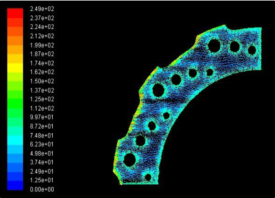

For disc 1 máximum heat transfer coefficient achieved was 249 W/m2K whereas for disk 2 máximum heat transfer coefficient achieved was 236 W/m2K.
Heat transfer coefficient basically defines how efficiently heat is released from a body. As disk 1 is having an aerodynamic advantage and better hole design pattern more heat transfer oceurs through disc 1 compared to disc 2. Further making grooves will naturally enhance the heat dissipation rate. Petáis can also be provided at the outer edge in order to increase heat transfer coefficient.
4. FINITE ELEMENT ANALYSIS
Finite element analysis of brake disc was involved of following steps:
4.1 GEOMETRY
Modelling was done in CATIA V5 according the dimensions of the disc mentioned above in table 1. This geometry then imported to ANSYS V16.2 for analysis purpose.
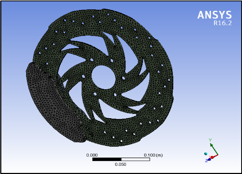
4.2 MESHING
Meshing is most important step in FEA, because it decides numerical convergence to the solution. Henee fine or coarse meshing have a great influence on the final results. In this project, fine meshing was done using triangulated surface mesher. Mesh size was selected as 4mm.
Figure 6 show discs with fine meshing. After meshing boundary conditions were applied on each disc.
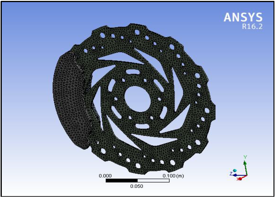
Figure 6 and Figure 7 shows mesh details of disc 1 and disc 2 respectively.
4.3 BOUNDARY CONDITIONS
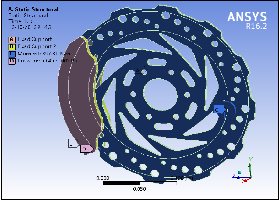
For the structural analysis, disc was fixed at mounting points on hub and at caliper. Moment is applied on the disc about the axis in a plañe perpendicular to the plañe of disc. Calculated pad pressure was applied on both the brake disc pads. Geometry for the structural analysis with boundary conditions is as shown in figure.
For thermal analysis, initial temperature of disc was set as 22°c. From the CFD simulation, convective heat transfer coefficient was taken as 249 W/m2-°k and 236 W/m2-°k for disc 1 and disc 2 respectively. Effect of radiation was also considered. Heat flow from the particular área of contact was calculated and applied on the geometry as shown in figure.
4.4 ANALYSIS
The analysis was carried out for both magnesium alloy and aluminium alloy by keeping carbón ceramics as pad material.
4.4.1 STRUCTURAL ANALISYS OF DISC 1
Figure 8 indicates applied boundary conditions for disc 1. Disc was fixed at hub mounting position. The outer edges of both the pads were fixed. Pad pressure of magnitude 0.546 Mpa was applied on both the pad surfaces. Moment of 397.312 N-m was applied about the center of the disc. Disc was analyzed for total deformation and factor of safety.
From the analysis with magnesium alloy as a material we can see from Figure 9, the máximum deformation was found to be 9.0232e-5 m. Figure shows deformation is highest at the outer edge and lowest at the inner edge where the fixed constraints were given.
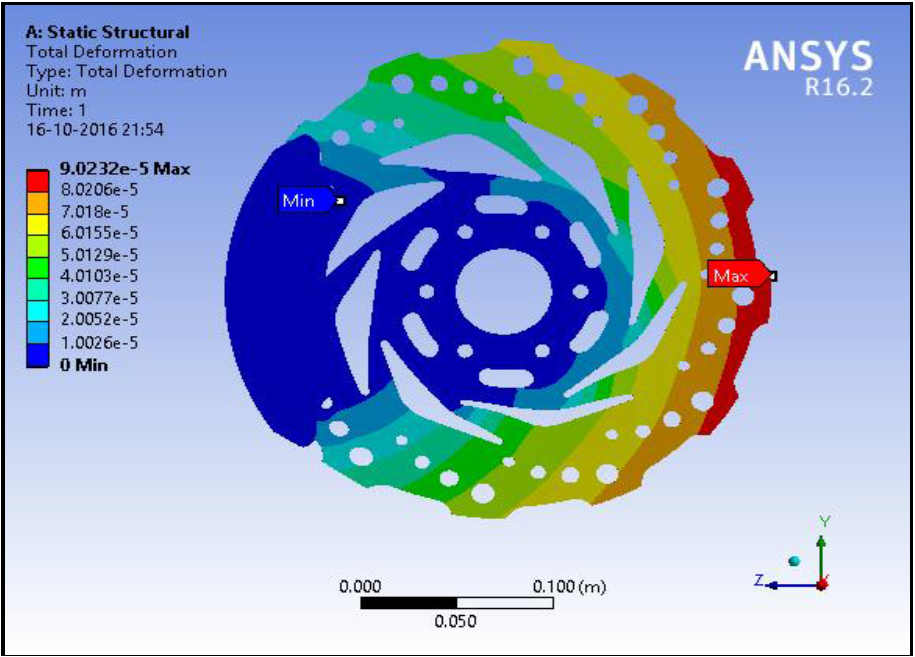
As the moment is provided at the centre of brake disc and clamping forces are generated at the contact región between disc and pads, the región in contact is held firmly by pads whereas the outer región i.e. diametrically opposite to that of contact tends to follow the rotation of disc resulting in greater deformation in outer región.
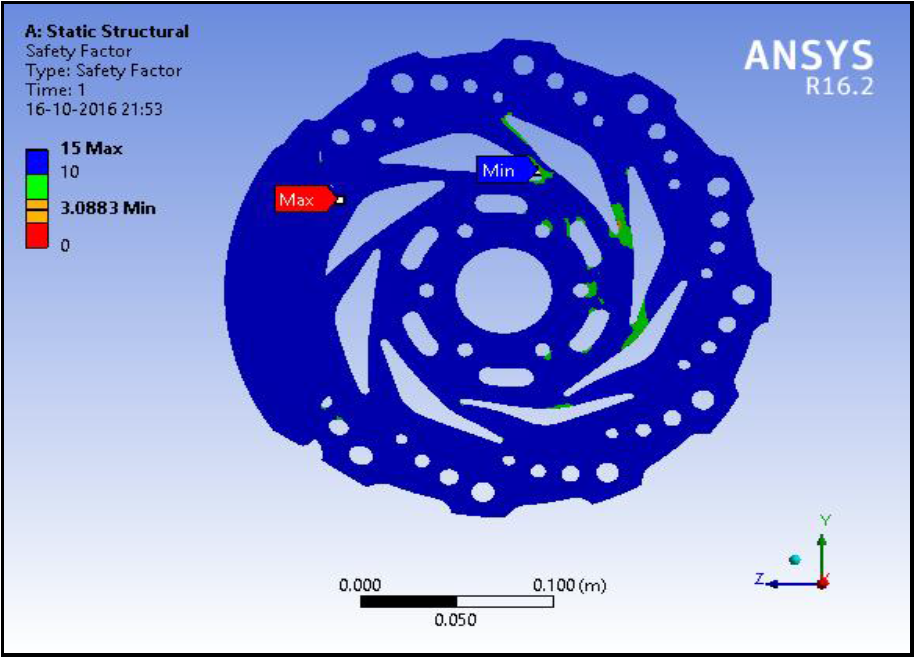
Figure 10 shows overall Factor of safety for Disc 1 with Mg alloy to be 3.0883.
By applying same boundary conditions with reference to Figure 11, the máximum deformation of disc 1 for aluminium alloy was found to be 5.725e-5 m which was comparatively less than that of magnesium alloy.

Figure 12 shows overall Factor of safety and it was found to be 4.4606 for aluminum alloy disc, which was greater than factor of safety for Mg alloy for disc 1 because of the higher strength of aluminium alloys.

4.4.2 STRUCTURAL ANALISYS OF DISC 2
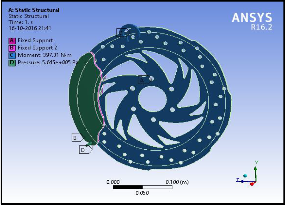
For disc 2, Figure 13 shows the applied boundary conditions. Then structural analysis was done for disc 2 by taking material as magnesium alloy and aluminium alloy. Again the brake pad material was kept same for entire analysis.
From Figure 14, Máximum deformation for disc 2 with magnesium alloy observed was 7.2909e-5 m.

Factor of safety achieved was 3.414 for disc 2 with magnesium alloy and shown in Figure 15.

Deformation is shown in Figure 16 and it was 4.629e-5 m for disc 2 with aluminum alloy which was lesser than that of disc with magnesium alloy.
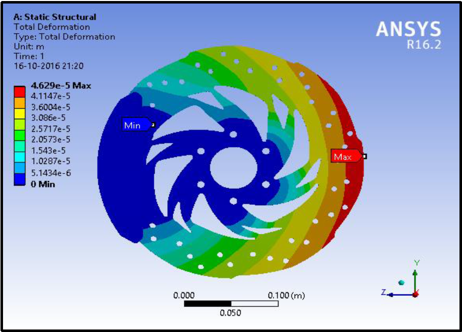
Overall Factor of safety with aluminium alloy was found to be 4.9642 as shown in Figure 17 and which is higher than that of magnesium alloy because of its high strength.

Global security factor basically represents the ability of brake disc to withstand the loading conditions. It is necessary to make sure that the Safety factor does not exceed the acceptable limit, as it would make brake disc over-safe resulting in unwanted loss of material in production.
4.4.3 THERMAL ANALISYS OF DISC 1
For thermal analysis of disc 1, initial temperature condition was taken into an account along with effect of radiation. Calculated heat flow was applied onto the geometry as shown in Figure 19 and Figure 20 for magnesium alloy and aluminium alloy respectively. The results were ploted distribution of temperature.

According to the calculations, heat flow was provided within the boundary of the contact área between pads and disc.
Brakes applied at high speed causes more heat to genérate. The temperature reached for these conditions was 549.86 °C.
4.3.4 THERMAL ANALISYS OF DISC 2
For disc 2, the same calculated heat flow was applied for both the materials. Figure 18 and Figure 21 shows the área on the disc where the heat flow was applied. Then geometry was analyzed for the temperature distribution across the disc.
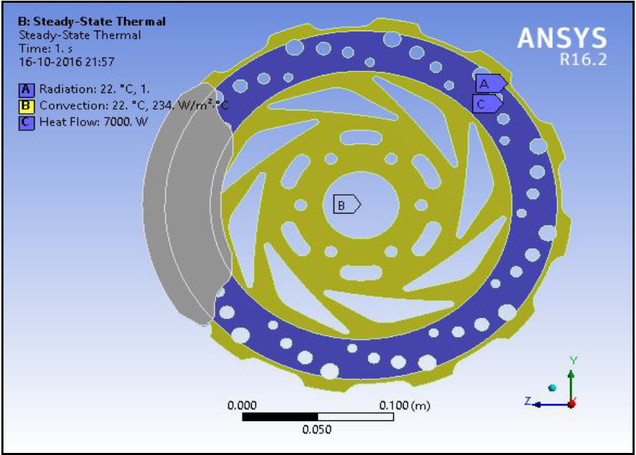

Heat flow was provided within the contact región between pads and disc as shown in Figure 21.
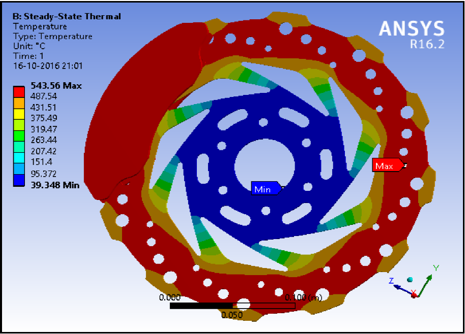
Air turbulence within the patterns plays an important role for heat dissipation. So the temperature achieved was less compared to others with magnesium alloy which can be seen from Figure 22.

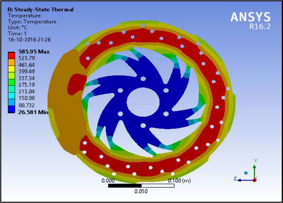
Friction is sole cause of heat. Area with máximum temperature represents high amount of friction. In accordance with Figure 23 for disc 2 with material as aluminium alloy, temperature observed was 585.95°C.
The temperature observed is quite on a higher side because we have considered extreme braking conditions i.e. a motorcycle must come to a halt from 100 km/hr to 0 km/hr within a specified distance of 22 m. Under frequent braking conditions, the temperature of disc reach up to 250 350 ° C. It is highly expected to have a temperatura exceeding normal conditions as the initial assumptions made are based on extreme braking conditions. Another reason for high temperature is due to smaller contact área with higher actuating forcé. Since our study is based on analysing the heat dissipation for different models, one can make use of greater contact área with lesser actuating forcé for limiting the máximum temperature.
5. RESULTS
Table 5 Results of structural analvsis for disc 1.
| Material | Aluminum Alloy | Magnesium Alloy |
|---|---|---|
| Deformation (mm) | 5.75E-05 | 9.02E-05 |
| Factor of safety | 4.46 | 3.083 |
Table 6 Results of structutal analysis fos disc 2
| Material | Aluminum Alloy | Magnesium Alloy |
|---|---|---|
| Deformation (mm) | 4.629E-05 | 7.29E-05 |
| Factor of safety | 4.96 | 3.414 |
Table 7 Results of thernal analysis fos disc 1.
| Material | Aluminum Alloy | Magnesium Alloy |
|---|---|---|
| Max temperature (o C) | 523.93 | 530.33 |
6. CONCLUSIONS
A. For Structural analysis:
For aluminium alloy as well as magnesium alloy, the deformation observed for disc 2 was less than that of disc 1.
Factor of safety achieved for disc 2 was slightly higher than disc 1.
From this we can conclude that design of disc 2 is better in terms of strength for both materials.
B. For thermal analysis:
Considering aluminium alloy as a same material for discs, it was observed that máximum temperature is on the higher side compared to disc 1.
Whereas in case of magnesium alloy design of disc 2 is more efficient in terms of heat flow through the disc. And temperature of disc 2 was also considerably less as compared to other discs.
Henee, from above results we can conclude that, compatibility of material with disc pattern also plays an important role for designing brake discs. In order to have better heat dissipation, disc 2 design with magnesium alloy can be used. Also for better braking performance in terms of strength, design of disc 2 is better.
As the performance of disc 1 is also within the acceptable range, one can make use of disc 1 with aluminium alloy as it does have better heat transfer coefficient which would naturally have an impact when it comes to heat dissipation through holes.
Measures to reduce deformation
The most important factor to be considered for minimizing the deformation of discs is redefining the contact área of pad with disc. Pads must be designed in such a way that they adhere properly with discs without creating any strain on operating conditions of disc. ABS can be considered as an option because the entire ABS module has information regarding the optimum braking conditions which makes sure that vehicle comes to halt without any squeaking of brake disc and skidding of tyres.

