


 text new page (beta)
 English (pdf)
 Article in xml format
 Article references
 Send this article by e-mail
 Cited by SciELO
  Similars in
SciELO
Similars in
SciELO 
 Permalink
1. Introduction
In micro devices, flow boiling into micro-channels seems to be one of the most efficient cooling solutions for high-power density electronic devices, being the main challenge the space limitation.
Research on this topic has been treated theoretically, numerically, and experimentally; Szczukiewicz et al. [1] have published a complete review. Despite the important research accomplishments that have been obtained over the last years, some aspects, including local physical mechanisms related to heat transfer, remain unclear [2].
Generally, numerical simulations provide an efficient tool to estimate the thermodynamic behavior dependent on geometry and operation conditions.
Numerical simulations of flow boiling have been performed in the past years [3-8]. Guo et al. [9] have published a complete review. Despite simulations needing to be compared with experimental results, they serve as a guide to design loops for cooling systems.
The work here presented is the beginning of a project that pretends to simulate for designing of micro-scale cooling systems. Part of the research team is working on the experimental activity. The project’s aim is to have a tool to design these systems before manufacturing.
In the present paper, the results of simulations for an evaporator are showed. The evaporator consists of a single 1-mm horizontal circular tube that receives constant heat flux. Inside the tube, fluid is forced to flow. By input physical geometry parameters and fluid properties, among them the outlet quality, the simulation computes the mass flux and the critical heat flux among others outputs.
1.1. Background (Theoretical framework, state of the art)
Cheng & Thome [10] have performed some simulations for flow boiling heat transfer and two-phase pressure drops in microscale channels using R236fa and
Karayiannis & Mahmoud [17] have compared the different integrated systems using micro-channels. Oudah et al. [18] have numerically simulated flow boiling R134a refrigerant’s heat transfer in a tube having 4.35 mm internal diameter; they claimed an enhancement in the local heat transfer coefficient when the temperature of saturation increased from
Yuan et al. [22] have performed a steady simulation model based on one-dimensional flow direction of flow boiling in micro-channel for refrigerants R134a and R1234ze(E), being to highlight that the local heat transfer coefficient: i) of R1234ze(E) is lower than that of R134a, and ii) decreases (in the two-phase region) along the flow direction, which indicates that the nuclear boiling is dominant. Majumdar et al. [23] have simulated, by solving mass, momentum and energy conservation equations, a configuration of fluid flowing in a vertical heated tube for water and for liquid nitrogen, comparing the experimental data with numerical predictions based on four different correlations, finding that, for the case of boiling water, the predictions using the correlations agreed with the experimental results, while there are large discrepancies for the case of boiling hydrogen. Son & Park [24], by introducing a new numerical phase-change model that reflects the thermal-fluidic discontinuities through the phase interface more faithfully, claimed that heir model exhibits superior consistency with the empirical correlation than the Lee model.
Wang & Wu [25] have proposed a novel battery thermal management system (BTMS) using the dielectric, non-flammable HFE-7000 refrigerant, improving the thermal performance of the battery module, showing good agreement between the numerical results and experimental data. Zhou et al. [26] have conducted a one-dimensional numerical study for the heat leak simulation, validating by the experimental data of the loop heat pipe, and showing that their model improves the prediction accuracy for radial heat leak. Bard et al. [27], by using a number of data science methods and techniques to accurately predict the heat transfer coefficient during flow boiling in mini/micro-channels, have proved that machine learning is an extremely useful tool when predicting the heat transfer coefficient across a variety of different fluids. Moradkhani et al. [28] developed a general explicit model for estimating the saturated flow boiling frictional pressure drop in macro and mini/micro channels heat exchangers, predicting the database with a reasonable value of average absolute relative deviation of 21.34%. Dai et al. [29] have numerically simulated, by the volume of flow (VOF) multiphase model, the flow boiling heat transfer process in a horizontal smooth copper tube, showing that the heat transfer coefficients of simulation have great accuracy with a numerical deviation of ± 20%.
For modelling of boiling in small channels there are a considerable number of heat transfer correlations. According to Sardeshpande & Ranade [30], one of the major difficulties in modelling two-phase flow is the determination of the geometry of the flow pattern. Kattan et al. [31] argue that the models based on distinguish between flow regimes should be seriously considered for general use. So, it seems that the flow pattern has a crucial role on heat transfer coefficient.
2. Methodology
The simulations have been performed for a smooth horizontal circular tube of inner diameter D and heated length L. A boundary condition of the second kind (Neumann condition), i.e., constant heat flux, has been imposed on the inner surface of the tube. The simulations are performed for steady state, one-dimensional (axial) conditions, using the differential axial distance
Figure 1 outlines the system under analysis.

The fixed input parameters are:
While the input parameters that have been tested according to the matrix showed in table 1.
Table 1 Matrix of tested parameters.
| ∆Tsub [K] | |||||
| Pin [bαr] | 0 | 5 | 10 | 15 | 20 |
| 0.5 | ✓ | ✓ | ✓ | ✓ | ✓ |
| 1.0 | ✓ | ✓ | ✓ | ✓ | ✓ |
| 1.4 | ✓ | ✓ | ✓ | ✓ | ✓ |
Figure 2 shows the flow chart of the used algorithm to simulate both, subcooled liquid flow and two-phase flow. During design of an evaporator, it is important to establish the desired flow pattern during two-phase flow, which is related to the quality. It is the reason to consider the outlet quality (
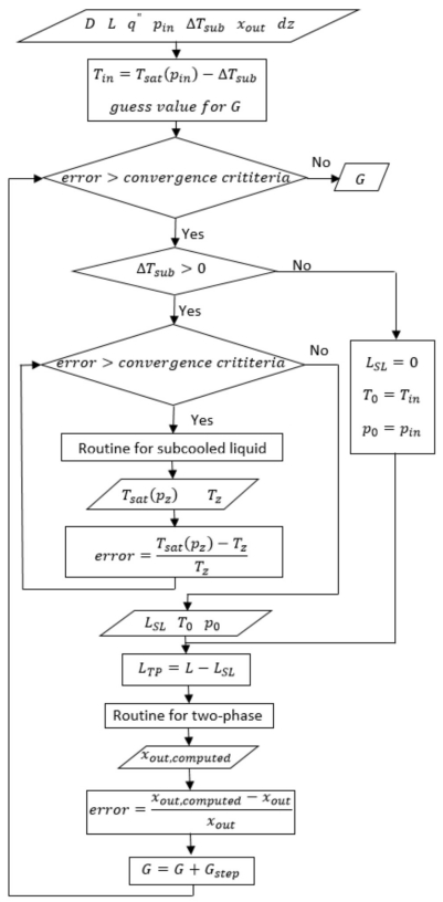
In this paper, a value of 0.3 has been used as fixed outlet quality, which could resemble, depending on many variables, an up limit of slug to annular flow. Others quantities for this variable should be analyzed for different applications. The mass flux, needed to maintain the input parameters, is the output of the algorithm. The algorithm has been written in Python. The fluid properties have been obtained using Refprop (version 9.1). All the properties are obtained as function of pressure and temperature.
The classification of the tube scale has been done in the next basis. For the subcooled liquid region, according to Kandlikar et al. [32] a minichannel is a channel whose hydraulic diameter is ranged
For the two-phase region, according to Kew & Cornwell [33], confinement effects are significant for channels having hydraulic diameters such that the confinement number is higher than 0.5, being the confinement number defined as
2.1. Subcooled liquid region
For the present analysis, the subcooling level must be
For
For
The aforementioned convergence means that the fluid just got the state of saturated liquid at the axial position z. This position represents the axial length from the tube inlet
Frictional pressure drop has been estimated, for developing laminar region, according to the equation 2 described by Shah & London [34] (based in the work of Hornbeck [35]).
Where
For fully-developed laminar region and turbulent region, frictional pressure drop has been estimated according to:
Where
So, for the present analysis, if
Just to point out, gravitational effect has not been taken in account due to the fact that the tube is horizontally oriented.
From an energy balance, temperature has been computed according to:
2.2. Two-phase region
The routine for two-phase has been performed by using the theoretical model developed by Revellin & Thome [36]. There, a system of five ordinary differential equations is solved for five dependent variables: liquid and vapor velocities and pressures,
Equations 4a and 4b have been derived by the conservation of mass. Equations 4c and 4d come from conservation of momentum. Finally, equation 4e is the Laplace-Young equation.
The system has been numerically solved using the 4th-order Runge-Kutta method imposing five boundary conditions for
As shown in the flow chart (see figure 2), the convergence is reached when
Once the mass flux has been computed, the entire algorithm runs again to get the critical heat flux. The convergence is reached when a minimal liquid film thickness occurs in the tube outlet, i.e. dry-out condition, according to:
Where
3. Results and discussions
The figures in this section show results as function of the subcooled level. The results here presented are the contribution in the study of flow boiling inside micro-tube, according with the parametric analysis of table 1.
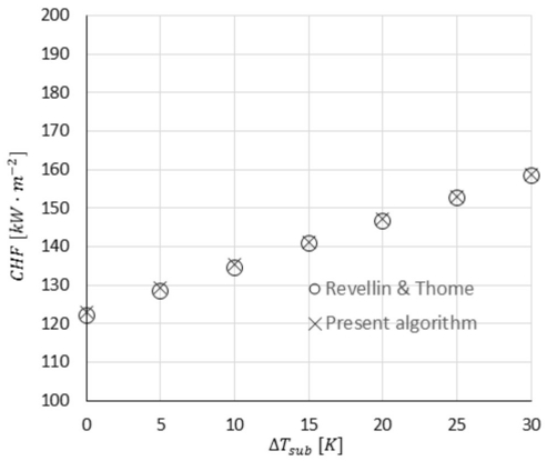
Verification of the present algorithm has been performed by solving the case presented by Revellin & Thome [36].
Figure 3 shows the comparison between the results of Revellin & Thome [36] and the results from the present algorithm. The maximum deviation has been 0.7%, for
Once it has been verified, some simulations have been run. Three inlet pressures are shown in the figures. Note that the value of
The CHF is an important parameter to design because this condition is always avoided.
Figure 4 shows the required mass flux according to the subcooled level and the inlet pressure.
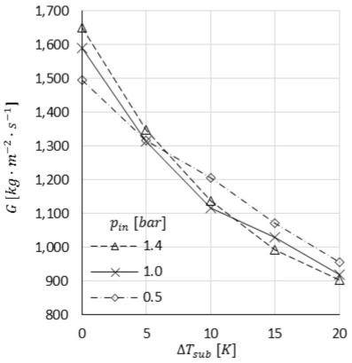
As expected, for higher subcooled level, less mass flux is required. For subcooled liquid entering to the tube, less mass flux is required for lower liquid temperature due to it can carry more energy (heat flux) along the tube.
There is not a regular tendency by inlet pressure comparison. For the case when saturated liquid enters to the tube (
From the point of view of the mass flux, in order to reduce the pump power, higher subcooled level should be chosen.
Figure 5 shows the ratio of length of two-phase and the total heated length according to the subcooled level and the inlet pressure.
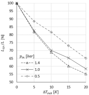
For the case when saturated liquid enters to the tube (
For higher inlet pressure, less length of two-phase exists. It seems that fluid properties for higher inlet pressure leads to need longer length of subcooled liquid in order to get the state of saturated liquid.
Figure 6. shows the pressure drop along the tube according to the subcooled level and the inlet pressure. It is possible to see a slight tendency to reduce the pressure drop for higher subcooled levels.
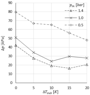
As high the inlet pressure as less pressure drop. It is because the fluid has more enthalpy for higher pressure. From the point of view of the pressure drop, in order to reduce the pump power, higher inlet pressure should be chosen. Note that this pressure drop is only of the evaporator. In order to choose a pump, it is necessary to analyze all the loop components.
Figure 7 shows the ratio of the actual heat flux and the critical heat flux according to the subcooled level and the inlet pressure. It is a very slight reduction of this ratio for higher subcooled levels, for higher inlet pressure, the actual heat flux is closer to the CHF; for example, for
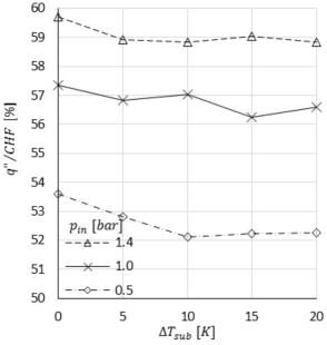
From the point of view of the CHF, it would be preferred the lowest inlet pressure in order to be farther of this condition. Finally, note that the decision of the inlet pressure is a quandary because it should be the highest thinking in the pump selection but the lowest thinking in the critical heat flux.
5. Conclusions
From the simulations for an evaporator showed in this paper, the next conclusions are found.
To choose the right pump, the highest subcooled level and inlet pressures should be preferred.
To avoid the critical heat flux condition, the lowest inlet pressure should be preferred.
The right inlet pressure is difficult to decide because is opposite for the point of view of pump selection and critical heat flux condition.
The results here presented are for a circular tube. The next step will be to simulate for a rectangular channel.
7. Authorship acknowledgment
César Manuel Valencia-Castillo: Methodology; Analysis; Resources; Documentary research; Original draft; Script. Giuseppe Zummo: Ideas; Analysis; Resources. Luca Saraceno: Ideas; Analysis. Felipe Noh-Pat: Methodology; Analysis; Documentary research; Script. Pedro Cruz-Alcántar: Script; Edition.
Nomenclature
| Symbol | Description | SI unit |
| Roman | ||
| A | Cross sectional area | m2 |
| cp | Specific heat capacity | J · kg-1 · K-1 |
| CHF | Critical heat flux | W · m-2 |
| dz | Differential axial length | m |
| D | Inner tube diameter | m |
| 𝑓 | Fanning friction factor | - |
| g | Gravitational acceleration | m · s-2 |
| G | Mass flux | kg · m-2 · s-1 |
| i | Specific enthalpy | J · kg-1 |
| L | Axial heated length | m |
| ṁ | Mass flow rate | kg · s-1 |
| p | Pressure | Pα |
| P | Inner tube perimeter | m |
| q´´ | Heat flux | W · m-2 |
| r | Radius of the vapor core | m |
| Re | Reynolds number | - |
| T | Temperature | °C |
| u | Velocity | m · s-1 |
| x | Mass quality | - |
| x+ | Dimensionless length | - |
| z | Axial distance from the inlet | m |
| Greek | ||
| δ | Liquid film thickness | m |
| Δp | Pressure drops | Pα |
| ΔT | Temperature difference | K |
| µ | Dynamic viscosity | Pa · s |
| p | Density | kg · m-3 |
| σ | Surface tension | N · m-1 |
| τ | Shear stress | N · m-2 |
| Subscripts | ||
| 𝑓 | Frictional | |
| i | Liquid-Vapor interfacial | |
| in | Tube inlet | |
| L | Liquid phase | |
| LV | Change of phase (when i) or Liquid-Vapor (when τ) | |
| LW | Liquid-Wall | |
| out | Tube outlet | |
| sat | Saturated | |
| SL | Subcooled liquid | |
| sub | Subcooling | |
| TP | Two-phase | |
| V | Vapor phase | |
| z | Axial local position | |
| 0 | Indicative for saturated liquid | |

