


 text new page (beta)
 English (pdf)
 Article in xml format
 Article references
 Send this article by e-mail
 Cited by SciELO
  Similars in
SciELO
Similars in
SciELO 
 Permalink
Introduction
Osteoporosis is defined as the loss of trabecular bone which in the lumbar section of the spine can be present when the average bone mineral density is < 0.8 g/cm2. According to Martínez-Quiñones et al.1, vertebral fractures of osteoporotic origin induce dorsal kyphosis, which can increase mortality by 23-35%, reduce respiratory vital capacity by 9% for each fractured dorsal vertebra, accelerate the sensation of fullness postprandial, and increase the degree of depression.
Patients with osteoporosis who have instability or deformities, fracture of vertebrae, or damage to the intervertebral discs need instrumentation in the spine as an orthopedic treatment. According to Burval et al.2 with the increase in the patients' life expectancy, surgeries are having major challenges in the reconstruction of the spine due to the increase in bone fragility in advanced ages.
Mechanical fixation of the spine in patients with osteoporotic vertebral degeneration remains a challenge for surgeons3. In the middle of operations, the vertebrae selected to insert the screws may fail, endangering the patient's life. Methods of transpedicular fixation with screws offer stability in the spine and have proved to be the most rigid posterior fixation methods in the thoracic and lumbar part of the spine4,5.
According to Alkaly and Bader6, despite the technological advances in the design of internal fixation systems, the loosening of the implants, the catastrophic failure in the bone-screw interface, the migration of material, and the loss of stability also constitute a serious complication in spine surgery in adults. It has been identified that the biomechanical factors that affect the fixation capacity of the pedicle screws are the design of the screws, the anatomical characteristics of the vertebral body and the pedicle (vertebrae geometry and the mechanical properties of the vertebral bone), and the techniques of insertion of the screw7.
The mechanical properties of the bone have a dependence on bone density, Seebeck et al.8 concluded that cortical tissue thickness and spongy bone density explain more than 90% of the variance of the final load of the screws under traction conditions and cantilever bending.
The conventional transpedicular screws and the cortical screws are two of the fixation techniques. Conventional transpedicular screws have a poor performance due to the reduction of spongy bone mass that can severely limit the fixation potential in patients suffering from osteoporosis. On the other hand, the trajectory of insertion of the cortical screws theoretically maximizes the grip with the cortical tissue and potentially improves the long-term fixation.
Biomechanical analysis contributes to study the behavior of the human body under different loading conditions9,10. In this direction, Sansur et al.3 were the first to perform a comparative study between conventional transpedicular fixation and cortical fixation following the physiological stresses in the osteoporotic lumbar spine. They found that the properties of transpedicular and cortical fixation were dependent on the level of the instrumented vertebra. Fixation with cortical screws exhibited a marked increase in the average load of failure in the lower lumbar segments. The transpedicular screw fixation showed an inverse tendency of lower failure loads in the lower vertebral elements and higher failure loads in the upper vertebral elements, probably secondary to the unique composition of the pedicle in the lumbar spine. On the other hand, Matsukawa et al.11 investigated how the extraction force of the pedicle screw was affected by the insertion trajectory. They concluded that the effects of different trajectories were influenced by the geometry of the vertebra.
Despite the advances related to the spinal instrumentation, it has not been possible to confirm the study of the behavior of the bone-vertebra interface for different bone densities. It is necessary to study the effect of bone density variation in the bone-screw interface, from a three-dimensional (3D) model of the lumbar section.
Materials and methods
Geometry model of the study
This study focuses on the stresses that originate in the screw-bone interface for different bone densities. The Finite Element Method (FEM) is the tool for excellence used in modeling the behavior of bones subjected to the action of mechanical loads12-14. The analysis carried out with the FEM, starting with the simplification of the real object and the simplified object is called model15. In the present research, a patient-specific model was generated, where geometry consisted of three vertebrae in segment L1-L3 of the images of the free software library 3D Slicer 4.8.0 (http://www.slicer.org)16. The medical images information was provided in the nearly raw raster data (NRRD) format which is a file format designed to support scientific visualization and to process images involving N-dimensional raster data17.
Once the images were imported into the 3D Slicer, we proceeded to render the data of the file in NRRD, according to the Volume Rendering module. The area of interest (region of interest) was selected and the work area was delimited with the Crop Volume tool. Segmentation of the images was performed with the Segment Editor module, where a layer was created for the bone tissue, which allowed to manually edit the groups of cuts and thus to eliminate surface imperfections, such as holes inside the solid, and avoid future errors in the mesh and in the analysis by MEF.
With the tool set surface smoothing, the smoothing of the geometric irregularities due to the segmented imperfections was performed. Smoothing prevents the generation of the surface mesh with triangles of poor quality. Once the process of editing the images was finished, the changes made to the model in STL extension were saved.
Subsequently, the geometry was imported into the Autodesk Meshmixer 3.3.15 software (Autodesk, Inc., CA, USA) to perform a new smoothing of the surface to eliminate the imperfections that were not possible to be eliminated in the 3DSlicer. In this same software, we converted the surface mesh into a solid element.
To separate the vertebrae and to insert the pedicle screws, the geometry was imported into the SolidWorks Premium 2018 software (Dassault Systemes SOLIDWORKS Corp., MA, USA). In this software, the starting and ending points of the screw trajectory were created, represented by the blue axes of figure 1A and 1B. The trajectory is parallel to the plates of the vertebral body (Fig. 1A). The holes of the screws were considered as a smooth of constant diameter. Reference planes were created perpendicular to the path of the screws for that portion of the vertebra volume that was subtracted. The geometry of the screw was created in a separate file, a diameter of 5.5 mm and a length of 30 mm were defined in the area of interaction with the vertebra.

Figure 1 Geometric model of L3 vertebrae with cortical pedicle screws. A: insertional trajectory of screws in sagittal plane view. B: in transversal plane view. C: assembly of screws inserted into the vertebrae.
Then, the assembly operation of the screws and the vertebra was performed, using the concentricity restriction between the diameter of the screws and the holes of the vertebrae (Fig. 1C). This geometry was exported in a file with Parasolid x_t extension (Siemens PLM Software, TX, USA).
With the geometry of the vertebrae processed, we proceeded to define the geometry model to be used in the simulation by the MEF. This simulation was carried out in the Abaqus CAE 6.14 software (Dassault Systemes SIMULIA Corp., MA, USA). Geometry was imported into the Abaqus. In the Part module, the work surfaces that will be used during the definition of the model were created. The geometry model carried the information about the positioning of the elements of the assembly, but it was necessary to define the interaction between the work surfaces.
Model of mechanical properties of the material
The mechanical properties of the bone can be considered as "unique" since they not only depend on the tissue being analyzed but also on the characteristics of the individual, the conditions to develop the mechanical tests, the preparation of the sample, and the speed of deformation. In addition, the bone is able to adapt to the loading conditions, modifying its structure because there is a large dispersion in the mechanical properties reported in literature18,19.
In literature, there is a great diversity in terms of the mechanical properties of a spongy tissue. The configuration of the trabeculae changes in each type of bone and within the same bone20-22. It is suggested that the modulus of elasticity (E) of the vertebral tissue is approximately 1 GPa, the great dispersion of values in this tissue is influenced not only by the stiffness of the trabecula but also by its orientation or disposition23-25. Banse et al.26 limited the yield stress range between 0.6 and 6.17 MPa.
In the definition of the mechanical properties of bone tissue, the relation between the apparent density and E (1) was used, as that expression E can range from 920 MPa (p = 0.35) to 100 MPa (p = 0.09), the Poisson's coefficient was set as 0.2. For each simulation, different homogenous values of E were assigned throughout the vertebra and it was considered as a material with isotropic behavior26-28.
E = 4750.ρ1.56(1)
Model of loads and constraints
In the mechanical fixation of a vertebral segment, the hardware releases the intervertebral disc of its compression loading, so it can be assumed that the upper vertebra of the instrumented segment receives the load of the adjacent segments by the upper plate, which is transmitted from screw to screw, from the upper vertebra to the lower ones through the hardware, and finally, the load is transmitted to the adjacent segment by the bottom plate of the lower vertebra (Fig. 2A).

Figure 2 Model of loads and constraints of the mechanical fixation of a vertebral segment. A: the hardware releases the intervertebral disc of its compression loading and the force is transmitted from screw to screw, from the upper vertebra to the lower ones through the hardware. All degrees of freedom of the screw head were removed and a compression load of 500 N was applied to the vertebra plate such as. B: upper plate for upper vertebra. C: bottom plate for the lower vertebra.
To simulate the behavior of the upper vertebra, a vertical compression load of 500 N was applied on the upper plate, which takes into account the effect of the paraspinal muscles and the intra-abdominal pressure in the balanced foot position27,28. A set of nodes was defined on the surface of the upper plate, which was selected as a reference to apply the concentrated load. The movement on the X, Y, and Z axes was eliminated on the outside face of the screw head (Fig. 2B).
To simulate the behavior of the lower vertebra, a vertical compression load of 500 N was applied to the bottom plate. A set of nodes was also defined on the surface of the bottom plate, which was selected as a reference to apply the concentrated load. The movement in the X, Y, and Z axes was eliminated on the external face of the head of the screws (Fig. 2C).
Geometry mesh
Subsequently, the geometric shape of the bone in the analysis is approximated by the division of the continuous solid into finite elements. This process is called discretization or meshing of the continuum. The elements are joined through the nodes and make up the mesh. The FEM is a numerical method and, therefore, its solution is approximate. The magnitude of the error depends on the correct definition of the model and the quality of the mesh.
Both the screw and the vertebra were meshed using tetrahedral elements with an average size of 1.6 mm, following a free mesh and using the advancing-front technique (AFT) and the Delaunay algorithm. The mesh of the vertebra contains 247,631 elements, while that of each screw 497 elements.
Results and discussion
During the analysis of a 3D object subjected to loads, the reactions that appear inside it are opposed to external forces. This way, stress within the body arises (force density per unit area). If an infinitesimal element is considered inside the cube-shaped body, normal and tangential stresses appear on each side. Through one of the resistance theories, the equivalent stress of each infinitesimal element is obtained. To determine these stresses, the theory of the potential energy of deformation or also known as von Mises was selected. The interpretation of the results was based on the maximum equivalent von Mises stresses, expressed in MPa.
In the analysis, two mechanical properties were defined for each material, one for the screw and one for the bone, and for the load condition to which both parts of the assembly are subject, the maximum stresses were much higher in the screw than in the vertebra, but the metallic body has greater strength than the bone so that bone failure is more likely to occur. In this sense, the maximum scale of the color gradient of the graph was redefined to highlight the stresses below 10 MPa since the stresses in the vertebra are less than this magnitude and it is also higher to the yield stress reported by the trabecular bone of the vertebrae (Fig. 3)21,29,30.

When the instrumentation of a vertebral section is performed, one vertebra receives the load on its upper plane and the other on the lower plane. The load is transmitted from one vertebra to the other through the screws and rods, leaving the intervertebral disc free from bearing loads. Fig. 3 shows the intensity of loads of the bone tissue of the vertebra which supports load on the upper plate. The highest values (3-5 MPa) were reported in the area where the screw hole ends, which is a sudden change of section, so this result can be considered with caution. In real conditions, this change of section does not exist since the hole ends in a point.
The stress in the order of 2-3 MPa was located on the surface of contact between bone and screw, located both in the vertebral body and in the apophysis, being slightly higher in the vertebral body and there was a tendency to decrease as it moves away from the vertebral body. The posterior half of the vertebral body was the most sensitive to high values of stress, while in the furthest areas from the axis of the screw, the stresses tended to their minimum magnitude (Fig. 4). There is a correspondence with the result obtained by Xu et al.28
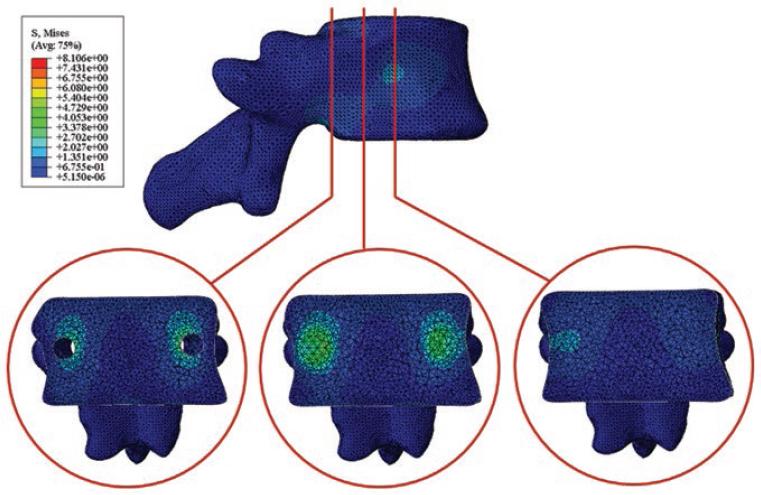
Figure 4 Behavior of maximum von Mises stresses in the inner of the vertebra when it was loaded on the upper plate.
Fig. 5 shows the behavior of the stresses in the bone tissue of the vertebra supporting the lower plate. As shown, there is a behavior similar to that obtained when the vertebra is subjected to compression loads in the upper plate. Again, the stresses in the order of 2-3 MPa are in the area of contact of the screw with the bone. There is a slight difference in the distribution of stresses. In the vertebrae with compression load in the upper plate, the amount of elements above the screw with the stresses is bigger than when the load is applied in the lower part and vice versa.

Figure 5 Behavior of maximum von Mises stresses in the inner of the vertebra when it was loaded on the bottom plate.
A load of 500 N was applied to the models analyzed. From the result obtained, it is recommended for the patient not to carry out heavy activities since a greater demand on the column results in an increase in stress, thus with an increase in the stress in the bone. According to the results of the stress analysis, the areas of contact between the screw are susceptible to bone tissue failure because they are close to the bone failure stress of 2.37 ± 1.14 MPa reported by Banse et al.26 These authors carried out the characterization of the mechanical properties and they discovered that the vertebral body can resist up to 6.17 MPa, but in the areas, where the bone density is close to 0.35 g/cm3.
The common problems of the implants are the loosening of the screw-bone interface, extraction, and insufficiency of the instruments after the lumbar arthrodesis (the catastrophic screw or hardware failure)6. Product of the working circumstances of the clamp, when the spine is bent forward, the screws tend to come out of the bone. On the other hand, due to the direction of the loads caused by the patient's weight, the screws can fail at shear loads. One aspect to take into account is the cyclical nature of the loads caused by the gear, which brings about the risk of failure due to fatigue, mainly in the concentration zones of stress located in the threads of the threads31.
As limitations of the model, only the compression loads in the vertebral body were considered in the present study. According to Matsukawa et al.11, the load in axial direction to the axis of the screw that can resist the bone before the loosening occurs is 1040 ± 268 N. Although with a marked effect on the screws, the fatigue caused by the cyclic nature of the loads brought about the march may also be present in the bone tissue and it can affect the screw-bone interaction, causing the non-resistance of the bone to the loads reported by Matsukawa et al.11
For future analysis, adjacent segments and intervertebral discs should be included, although only the screw-bone interface was studied, other researchers suggested that spinal fixation is a possible cause of degeneration of adjacent disc segments. It has been suggested that mechanical loads and stresses alter the structure and the failure properties of the disc, which eventually leads to the degeneration of the intervertebral discs. In addition, the greater rigidity induced by the pedicle screws could be attributed to the main function they perform to restrict the fused joint during flexion-extension loading conditions. To counteract the damage in discs of the adjacent segments, it is decided to reduce the rigidity of the instrumented segment.
According to Elmasry's study32, the mobility and stresses experienced by a spinal segment increase when neighboring segments are fused. Therefore, control of the stresses generated in the adjacent segment due to the implanted construction provides an indication of the potential risks of degeneration in the adjacent intervertebral disc.
According to the study of mobility of the intervertebral discs in posterior pedicle fixation performed by Rohlmann et al.27, to achieve a natural intervertebral movement, an elastic modulus of the low rod is required, while to reduce the intradiscal pressure, a high rod rigidity is required. On the other hand, to reduce the forces of the facet joint, it is necessary that the connection between the rod and the pedicle screw is rigid. Hence, it can be deduced that the degree of mobility of the instrumented spinal segment will be sacrificed.
Conclusions
According to the analysis of stress distribution, the zones of contact between the screw and the bone are susceptible to bone tissue failure because they are close to the stress of bone failure of 2,37 ± 1.14 MPa reported in literature. The posterior half of the vertebral body was the most sensitive to high values of stress, while in the areas furthest from the axis of the screw stresses tended to their minimum magnitude. From the obtained result, it is recommended that the patient cannot carry out heavy activities because a higher demand on the spine results in an increase in strength, therefore, an increase in the stress inside the bone.

