


 text new page (beta)
 English (pdf)
 Article in xml format
 Article references
 Send this article by e-mail
 Cited by SciELO
  Similars in
SciELO
Similars in
SciELO 
 Permalink
Introduction
Society development is always proportional to the energy consumption per member. Since the industrial revolution, developed economies have been supported by the ways that they store and collect their energetic resources, from the food preservation to the complex systems developed to move oil for its commercialization, by considering also the human adaptation to the ambient conditions and the cooling of high performance machinery needed by the most lucrative activities of social communications [1, 3].
Because of the industrial and commercial background, the cooling technologies based on vapor compression are the most used to solve the social activities listed in the previous paragraph; there are many reports about the impact of these systems in the economy and in ambient contamination. For example it has been estimated that in 1997 around one billion of these systems were installed in the U.S. [4] and in 2011 more than eleven terawatts were used to energize these cooling systems [3].
In this context cooling systems based on vapor compression are facing a disruptive scenario, which has been mainly seen by two fronts: firstly the ambient preservation, if it is considered that each of these cooling systems produces an average of two tons of carbon dioxide per year [5], and second the development of new technologies for cooling purposes, which performances are close to get the same energy behavior that the vapor compression systems [6-8].
This work has been developed with the intention of improving the energy performance of the current commercial cooling appliances which are based in vapor compression systems. The dynamic model for this cooling system has been obtained from a set of experimental tests for the dynamic behavior characterization, which have been developed by considering five levels of thermal load (100%, 75%, 50%, 25%, 0%) and with the ambient temperature fixed in an ambient conditioning test chamber. The future intention is to develop an algorithm for its control and its energy optimization once the dynamic model has been validated.
II. Materials and equipment
The cooling process by energy transportation can be defined as the one in which the temperature of a confined space (cooling chamber) is lowered by heat removal. This heat inside the volume is removed through a heat exchange process that transports it to another place outside the confined volume; being the energy transportation media in this case a refrigerant flow.
i. Cooling systems based on gas compression
Essentially a cooling system based on vapor compression is a thermodynamic system that uses a compressed fluid to transfer heat; this fluid is known as refrigerant [9, 10]. In the current commercial systems the fluoro-carbons are used as the preferred refrigerants, because of their thermodynamic properties that are the most suitable for energy storage and its transportation, since their boiling points are low due to their high evaporation heat, and also because they have a moderate density in their liquid phase, but in their gas state their density is high [11].
The cooling system based in vapor compression mainly consists of: a compressor, a condenser, an expansion valve and an evaporator. The diagram of the Fig. 1 illustrates the simplest setup of these cooling systems.
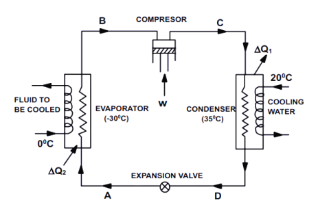
The ideal thermodynamic cycle of cooling systems based in vapor compression, as the one shown in Fig. 1, starts with the isotropic compression of the refrigerant flow that is entering to the compressor as vapor with high temperature and low pressure. The refrigerant is compressed to a high pressure and thus at a constant volume the refrigerant temperature also increases.
The refrigerant leaves the compressor with a high temperature and a high pressure, so while it flows through the condenser, the refrigerant fluid is condensed. Due to this condensation an isobaric heat transmission is performed from the refrigerant to the surrounding fluid. Then, the refrigerant leaving the condenser is liquid but it has the same high pressure with a lower temperature.
When the refrigerant passes through the expansion valve its pressure decreases and assuming a constant volume at the expansion valve then its temperature also decreases. While the refrigerant is flowing through the evaporator, it has both a low pressure and a low temperature, which is lower than the temperature of the surrounding fluid in the confined space, and again an isobaric heat transmission is performed from the confined space to the refrigerant. So the heat extraction is completed.
ii. Cooling systems modeling
The state of the art in the cooling systems modeling is mainly focused on three paradigms: thermodynamics, dynamical systems and smart algorithms. The thermodynamic models are based on the energy and mass conservation laws, so that they do not consider transient states. They are grounded on thermodynamic states of compressible gas and their static interaction through the thermodynamic cycle previously described [13, 14].
For sure, the dynamics of these systems are nonlinear, then several efforts to model its behavior with smart algorithms haves been done [15-17], but these models do not have physical interpretations so the systems designers are not able to interpret their results to increase the performance of their designs.
In the case of dynamical systems, the most complete methodology is based on the thermodynamic relationships of its variables but their dynamical momentums are also considered, then their models have a big set of state variables which are related with nonlinear equations [18].
iii. Dynamical model for cooling systems
All these models are too complex to be implemented for the tuning of a control algorithm into the hardware of the current commercial cooling appliances, so the proposal of this work is to get a mathematical model based in linear dynamical systems simplified for its industrial implementation in the current technologies of cooling systems based on vapor compression with linear compressors.
The dynamical model is grounded in the next set of considerations:
1.- The thermal behavior of the confined volume into the cooling chamber is as slow as it needs to be to despise the airflow turbulence which can affect the spatial distribution of the temperature inside, then this temperature can be considered homogeneously into the entire confined volume.
2.- The heat transfer between the refrigerant and confined volume is performed all along the evaporator heat exchanger, so the heat source (for extraction) is considered punctual and it affects homogeneously the confined volume temperature.
3.- In the same way the refrigerant temperature along the evaporator is considered homogeneous once the heat has been transferred.
With this statement the mathematical model of the cooling appliance based in vapor compression has been expressed with a set of linear equations which define the dynamical system as:
Thermal energy dynamics into the cooling chamber
Thermal energy interchange into the evaporator device
Thermal energy transportation capacity of the coolant
and
Mechanical energy into the compressor device
where:
Q(t) |
Heat removed from the thermal load at the confined volume, |
|
Temperature inside the confined volume, |
|
Ambient temperature, |
C |
Thermal capacitance of the confined volume component, |
R 1 |
Thermal resistance of the wall that confines the volume of the cooling chamber, |
|
Homogeneous temperature of the refrigerant at the evaporator, |
q(t) |
Refrigerant mass flow through the evaporator heat exchanger, |
R 2 |
Thermal resistance of the refrigerant pipeline along the evaporator geometry, |
K 1 |
Thermal constant of the relationship between heat extraction and refrigerant flow, |
ω(t) |
Angular speed of the compressor motor, |
K 2 |
Constant for the relationship between refrigerant flow and compressor speed, |
F(t) |
Frequency set point to realize an angular speed at the compressor motor, K 3: Constant for the relationship between compressor speed and frequency set point, and |
K 4 |
Constant for the relationship between compressor acceleration and frequency. |
Equation 1 describes the dynamic of the heat transfer between the confined volume and the evaporator surface inside the cooling chamber, while Equation 2 defines this heat transfer between the evaporator surface and the refrigerant flowing inside the evaporator pipeline. Equations 3 and 4 describe the dynamic relationship between the refrigerant flow, the compressor motor speed and the frequency set point for the motor driver to achieve the speed requested.
This mathematical model has been synthesized to study the linear dynamics between the most important variables which are measured and considered in current commercial cooling appliances, taking the frequency set point for the driver of the compressor motor as the only degree of freedom to modify the internal temperature of the cooling chamber and considering the thermal and dynamic coefficients that can be modified by the industrial designers. Then the linear space state of this model can be represented as:
The matrices coefficients would be constants if the model were entirely linear, but in this case to get a better approximation, these set of parameters have been defined for the five levels of thermal load percentage; so the main hypothesis of this model is that the nonlinearity of this cooling phenomena can be a thermal load function.
It is important to highlight that the electrical and mechanical dynamics of this model are much faster than the thermal dynamics, so the electro mechanical time constant is bigger than the thermal one, but to know their magnitude a set of experiment was developed.
Experimental methods
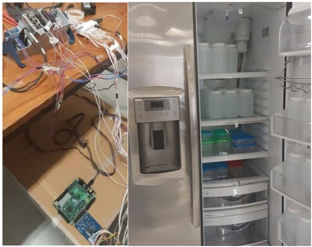
In this work, the experimental setup consisted in a modified refrigerator, which dynamics behavior of the internal temperature was monitored through two instrumental systems. Table 1 lists the refrigerator and the instrumentation systems technical characteristics, as well as the experimental testing variables magnitudes.
Table 1 Technical data of the experimental cooling system.
| Refrigerator Characteristics | Experimental testing variables | ||
| Refrigerant | RC14 mixture | Ambient Temperature | 24 °C |
| Capacity | 0.75 m3 | Refrigerant Temp. | 4.4 °C (in chamber) |
| Linear Compressor Systems | Instrumentation 1 | NI - CompacDAQ | |
| Compressor Power | 1.8 KW | Thermocouples | |
| Controller | Spartan III (FPGA) | Instrumentation 2 | LICORE ICE Bug |
| MEMs Sensors | |||
The instrumental systems were controlled through a virtual instrument, which acquires the sensors signals and control the variables activation with a FPGA controller. Fig. 2 shows both the external hardware of the virtual instrument and the cooling chamber of the concerned refrigerator.
The experimental validation of the proposed model (5) was focused on obtaining the time constants for each electromechanical and thermal subsystems, and as well as mentioned, these constants were obtained from the dynamical response of the cooling appliance while working with five levels of thermal load.
The characterization testing procedure was developed in an ambient conditioning chamber available at LaNITeF (Mexican Laboratory for Cooling Technologies Research). Taking in advantage the instrumentation systems in this laboratory, the refrigerant temperature was also measured to confirm that its average value along the evaporator geometry had a constant behavior and that it was close to its boiling point. Meanwhile the compressor motor speed was also set in 32 rpms and as well as shown in Fig. 2 the compressor dynamics just had two options with or without thermal load.
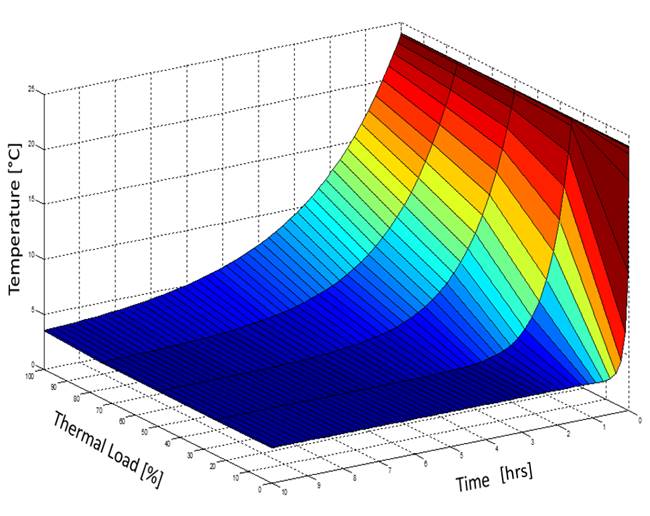
In the Figs. 3 and 4 the dynamical behaviors of each subsystem obtained experimentally are shown, where the transient response is illustrated while the entire system starts to work to achieve the refrigerant temperature inside its cooling chamber.
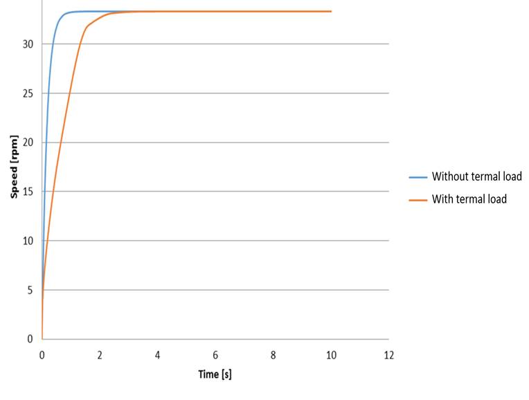
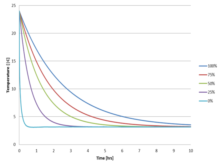
Figure 4 Experimental response of the thermal subsystem (for the five levels of thermal load percentage).
Fig. 3 shows that the inertia moment of the electromechanical subsystem of the refrigerator does not change with relation to the thermal load level, it does only in the case that this load is absent. On the other hand, the thermal load level strongly affects the thermal time constant, as illustrated on Fig. 4.
Model predictions results
In terms of the theoretical proposal to get the mathematical model for the dynamic behavior of a cooling appliance by considering the thermal load effects, simulation results of the proposed model (5) considering the same scenarios of the experimental testing are shown in Fig. 5. These internal temperature behaviors for the different levels of thermal load, were obtained by applying the set of time constant values calculated from the experimental results and listed on Table 2.
Results discussions
Based on Table 3 and Fig. 6 results, it can be said that model simulations have almost the same dynamical behavior than the cooling appliance tested, and their thermal responses are coherent with the ones reported previously by authors in two postgraduate thesis [19, 20]. So that, with this validation of the cooling appliance model which considers the non-linear effect of the thermal load in the dynamic behavior of the internal temperature, it can be applied to synthesize a control algorithm to accurately compensate the thermal inertial moment and get an optimized performance in future works.
Table 3 Model simulation errors respect to the experimental values.
| Experimental Results | Rodriguez Model [19] | Dominguez Model [20] | ||||
|---|---|---|---|---|---|---|
| Load level | Average error at steady state | Peak error at transient state | Average error at steady state | Peak error at transient state | Average error at steady state | Peak error at transient state |
| 0% | 5.2 % | 4.3 °C | 6.7 % | Does not reported | 8. 0 % | 5.4 °C |
| 25% | 4.5 % | 3.6 °C | 5.8 % | |||
| 50% | 3.0 % | 2.2 °C | 5.0 % | |||
| 75% | 4.3 % | 3.2 °C | 6.1 % | |||
| 100% | 5.0 % | 3.8 °C | 7.2 % | |||
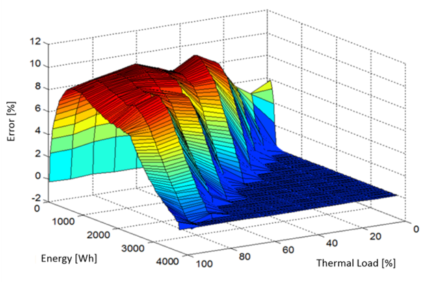
Differences between electromechanical and thermal time response magnitudes are consistent with at least their magnitude orders. Also the negative signs indicate that this is a stable system as the one that was experimentally characterized here.
The non-constant geometry of the surface response from the internal temperature shown in Figs. 4 and 5, highlights the non-linear behavior of this cooling appliance, therefore with these results it can be said that this non-linearity depends on the model (5) coefficients, which look more like a function of the thermal load.
Conclusions
The main hypothesis that considers the time responses as a function of the thermal load has been verified, by getting a considerable accurate (see Table 3) dynamical model for the cooling system.
By considering the experimental validation of the non-linear model for this cooling appliance based in vapor compression exposed here, the designers can modify their designs based on the time responses to increase the energetic performance of these cooling appliances. Also control engineers have the ability to synthesize and tune control algorithms with the intention of optimizing the energy performance.

