


Serviços Personalizados
Journal
Artigo
 texto em
  Inglês (pdf)
 Artigo em XML
 Referências do artigo
 Enviar este artigo por email
Indicadores
-
 Citado por SciELO
 -
 Acessos
Links relacionados
-
 Similares em
SciELO
Similares em
SciELO
Compartilhar

 Permalink
Revista ALCONPAT
versão On-line ISSN 2007-6835
Rev. ALCONPAT vol.6 no.2 Mérida Mai./Ago. 2016
https://doi.org/10.21041/ra.v6i2.138
Applied research
Experimental analysis of various configurations of metal sheets in the reinforcement of flexion of reinforced concrete beams
1 Departamento de Engenharia Civil; Laboratório Experimental de Estructuras (LEE); Universidade do Extremo Sul Catarinense (UNESC) - Criciúma/SC; Brasil.
The external structural reinforcing steel, in the way of steel sheets attached with epoxy adhesive, is an option to increase the load capacity of reinforced concrete elements. This study evaluated concrete beams reinforced with steel sheets SAE 1020 of different thicknesses (0.75, 1.50, and 2.25 mm), longitudes (80 and 150 cm), and configurations (U-shape or flat) with the purpose of reviewing and comparing the best practices with sheets adhered to the structural reinforcement. Twenty-one beams were built with a cross-section of 12 x 20 cm and a longitude of 200 cm, with C25 concrete, and flexion frame with 2 Ø10 mm. The beams where subject to a four-point flexural test, which allowed analyzing the optimal loads and vertical displacements. Thus, a comparison relative to the performance of the beams is presented.
Keywords: structural reinforcement; cast steel plates; reinforced concrete beams
O reforço estrutural externo com chapa metálica colada com adesivo epóxi é uma opção que possibilita aumentar a capacidade de carga em elementos de concreto armado. Este trabalho avaliou experimentalmente vigas de concreto armado com reforço de chapas de aço SAE 1020 de diferentes espessuras (0,75; 1,50 e 2,25 mm), comprimentos (80 e 150 cm) e configurações (perfil U ou simplesmente plana) com intuito de revisar e comparar as melhores práticas de reforço estrutural com chapa colada. Foram fabricadas 21 vigas com seções transversais de 12x20 cm e comprimento de 200 cm, utilizando concreto C25 e armadura de flexão com 2 Ø10 mm. As vigas foram submetidas a ensaios de flexão em 4 pontos, o que permitiu analisar as cargas últimas e deslocamentos verticais. Como resultado, apresenta-se um comparativo de desempenho das vigas.
Palavras-chave: Reforço estrutural; chapa de aço colada; vigas de concreto armado
El acero de refuerzo estructural externo, a través de chapas de acero pegadas con adhesivo epóxico, es una opción para incrementar la capacidad de carga de elementos de concreto reforzado. En este estudio se evaluaron vigas de concreto reforzadas con chapas de acero SAE 1020 de diferentes espesores (0.75, 1.50 y 2.25 mm), longitudes (80 and 150 cm) y configuración (en forma de U o plana) con el propósito de revisar y comparar las mejores prácticas con chapas pegadas al refuerzo estructural. Se elaboraron 21 vigas construidas con una sección trasversal de 12 x 20 cm y una longitud de 200 cm, con concreto C25 y armadura de flexión con 2 Ø10 mm. Las vigas fueron sometidas a ensayos de flexión en 4 puntos, lo que permitió analizar las cargas últimas y desplazamientos verticales. Como resultado, se presenta una comparación relativa al desempeño de las vigas.
Palabras clave: refuerzo estructural; placas de acero coladas, vigas de concreto reforzado
1.Introduction
The condition for the recuperation services and the reinforcement of the concrete structures depends on the precise analysis of the causes that make these necessary, as well as on a detailed study of the effects produced. In some cases, to guarantee the stability of the construction, there is need for structural rehabilitation or reinforcement (Silva Filho and Helene, 2011; Jumaat and Alam, 2008). Having clarified this factor, the adequate technique is chosen, which includes the careful selection of the material and equipment to be used, as well as the necessary labor for the execution of the work. Reinforcement is characterized as an activity specific for the cases in which the resistance and/or rigidity of a structure is sought to be increased. (Helene, 2000; Alfaiate and Costa, 2004; Tisot, 2010).
Reinforcement by the external addition of casted metal sheets is characterized by the bond of the surface of the concrete with steel sheets, using a resin with a high adhesion capacity and mechanical resistance. This is an option for the reinforcement of concrete elements, it is quick and simple to execute, and it is mainly recommended when it is necessary to reinforce the structure within a short time, or when it is not possible to make significant changes in the geometry of the piece (Campagnolo et al., 1994; Santos, 2008; Aykac et al., 2013). At the end of the processes, a structural element comprised of concrete-resin-steel is obtained, which provides the structure with a higher resistance than the requested efforts. Consequently, a more rigid element is obtained that deforms a little before starting to collapse. It is fundamentally important that the resin utilized to bind the concrete-steel is of proven quality and that the surface of the concrete and steel have been duly prepared (Cánovas, 1998; Cánovas, 1985). The adhesion to bind the metallic sheets is done using epoxy resins, because they show an adequate modulus of rigidity and excellent adhesive properties with concrete and steel, as well as low retraction during the curing process, all of which guarantees the integrity of the contact surface (Melo Júnior, 1997; Patiño, 2005; Simões, 2007).
The adherence between concrete-resin-steel is primordial for the good functioning of the reinforcement, as it provides the transference of stress between the elements. Studies done show different solutions to prevent types of rupture due to failure in adherence and the separation of the sheet, for example: an increase in the relation width/thickness of the sheet; finishing of the sheets close to the supports; and the use of anchor bolts and other devices to anchor the sheets (Oehlers, 1990; Hussain, 1995; Ali, 2005; Simões, 2007; Narayanamurthy, 2012). Another important factor to improve the durability of the reinforcement is to carry out a treatment with anticorrosive paint on the external surfaces of the sheet that are not in contact with the epoxy resin (Souza; Ripper, 1988). In this context, the selection of the adequate configurations and techniques are fundamentally important for the good mechanical performance of the structural reinforcement (Perelles et al., 2013), in addition to providing a better cost/benefit relation on the rehabilitation process of the structure.
The objective of this study is to experimentally evaluate the carrying capacity of reinforced concrete beams with different configurations of metallic reinforcement using steel sheets SAE 1020: i) different thicknesses (0.75 mm, 1.50 mm, and 2,25 mm); ii) longitudes (80 cm and 150 cm); and iii) either a U-shape or flat. The end goal is to review and compare the practical improvements of structural reinforcement with casted sheets.
2. Experimental procedure
Twenty-one beams with 12x20 cm cross-sections and a longitude of 200 cm were casted out of concrete with an average resistance to compression of 25 MPa at 28 days of age, and the reinforcement used steel CA-50 with 2xØ = 10 mm (power 3 - x/d = 0.2893). The abutments utilized had Ø=5 mm and a spacing of 10 cm. Figure 1 shows the details of the reinforcement used on the beams.
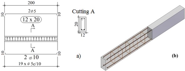
Figure 1 Details of the reinforcement on the beams - (a) Longitudinal detail; (b) Perspective of the reinforcement.
The beams were casted using immersion vibrators, using 2.5 cm plastic separators to ensure the coating of the reinforcement. Figure 2 shows the manufacturing sequence of the beams.
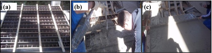
Figure 2 Manufacture of the reinforced concrete beams - (a) Molds with the reinforcement ready for casting; (b) Casting and vibration; (c) Leveling of the concrete in the molds.
The uncasing processes of the beams took place after 7 days. At 28 days, the beams were subjected to four-point flexural tests, which permitted the analysis of the final loads and vertical displacements. For the control of the resistance to compression of the concrete, 12 cylindrical (cps) test tubes were casted (Ø10x20 cm) to be tested at 7 and 28 days (3 cps per age/2 castings), and a slump-test was carried out to verify the workability of the concrete. The beams were divided into 7 groups with 3 samples each, as shown on Table 1. The beams from groups A, B, C, and D were manufactured in the same cast as the beams from groups E, F, and G, though with different castings. The beams of groups A and E were taken as reference for each casting. Groups E, F, and G were prepared using the most satisfactory result among the thicknesses of the sheets for groups B, C, and D.
Table 1 Distribution of the groups of reinforced concrete beams.
| Reference beams without reinforcement | Beams with straight sheets with different thicknesses | Beams with U-shape sheets with different longitudes |
|---|---|---|
| Group A | Group B (0.75 mm) | Group F (150 cm) |
| Group E | Group C (1.50 mm) | Group G (80 cm) |
| - | Group D (2.25 mm) | - |
2.1 Application of the reinforcement - 1 st stage: straight sheets with different thicknesses.
To implement the structural reinforcement, steel sheets SAE 1020 with a width of 12 cm and a longitude of 150 cm were used. The structural adhesive utilized was EP, an epoxy-based bicomponent of the Bautech® brand with the following characteristics: high adhesion, chemical and mechanical resistance, pre-dosage material, impermeable to water and oil, in addition to an initial hardness after 12 hours, and total curing in 7 days. The application of the epoxy structural adhesive on the beams followed the supplier’s recommendations, starting with the preparation of the substrate in which the application surface was cleaned of dust, oils or any substance that could damage the adhesion, carrying out this process with the use of a steel brush. The preparation of the epoxy structural adhesive was done through the homogenization of the components separated by hand. Subsequently, component B (hardener) was added to component A (resin), mixing for 5 minutes. The application of the epoxy structural adhesive was done with the help of a spatula over the entire surface to be casted, with a minimum thickness of 2 mm and a yield of approximately 0.7 kg/m2.
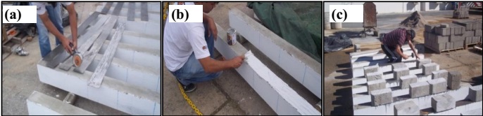
Before the application of the adhesive, grooves were made on the steel sheets with an electric sander to improve the adherence conditions along with the concrete surface. After fixing the sheets, they are subject to a quick and uniform pressure as to eliminate the excess resin. This pressure is applied with a rubber mallet. Subsequently, concrete blocks are placed at the extremes and on the region of the sheets, maintaining this for 7 days while covered with a plastic canvas. The application of the epoxy structural adhesive on the main beams was done at 21 days, and the flexural test at 28 days after casting. The substrate preparation stages of the epoxy structural adhesive, as well as the application of the steel sheets on the beams can be seen on Figure 3.
2.2 Application of the reinforcement - 2 nd stage: profile of the U-shaped steel with equal thickness.
From the results obtained with the tests of groups B, C, and D, the beams of groups F and G were prepared and reinforced with the steel profile SAE 1020, with a base of 12 cm, and wings with a height of 15 cm and a thickness of 0.75 mm (U-shaped profile); with group F having a longitude of 150 cm and group G having a longitude of 80 cm. The difference in the longitude of the sheets was premeditated to evaluate the area with the greatest concentration of stress, which is on the application points of the load, that is, on the central third of the beam.
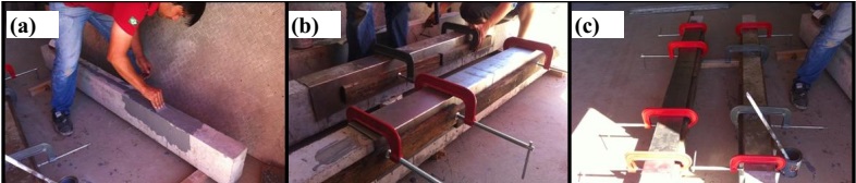
The adhesive utilized was the same as the one described on point 2.1. The application can be seen in Figure 4, having been carried out in accordance with the manufacturer’s specifications for the two longitudes of the profile: (i) execution of the grooves on the surface of the steel for a better adherence between the profile and the surface of the concrete; (ii) concrete surface without dust or oil, or any substance that could affect the adhesion, cleaned with the use of a steel brush; (iii) mixture of components A (resin) and B (Hardener), made within 5 minutes; (iv) application of the epoxy adhesive on the beams using a minimum thickness of 2 mm; (v) placement of the fasteners (sergeants) so that the steel profile can be pressed as close as possible to the beam, favoring the adherence of the profile to the concrete. This system was maintained for 7 days.
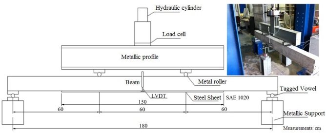
2.3 Four-point flexural test
It can be observed in Figure 5 that the beams are placed on a metal portico, where the load was applied through a hydraulic cylinder with a capacity of 500 kN, transferred to the central thirds of the beam through the metal profile while supported on two wooden rolls. The load increment values throughout the tests were obtained from a load cell positioned on the base of the cylinder. The displacements in the central span of the beam were measured from the 2 inductive displacement transducers (LVDTs) with a reading capacity of 100 mm, which were placed on the opposite sides of the central span of the beam to obtain the average of the values for a better consideration of the central displacement of the beam. To acquire the data the Quantum X® system was used, which utilizes the Catman Easy® software, both having the HBM brand.
The verifications were done to analyze the behavior of each group at different instances of load application: (i) at the maximum displacement (L/250) allowed by the standard ABNT NBR 6118:2014; (ii) at the rupture load; (iii) separation of the sheet and breakage mode.
3. Results and discussions
The result of the settling was of 11.0 cm for the concrete of groups A, B, C and D, and 10.0 cm for the concrete of groups E, F, and G. The results obtained from the tests on the axial resistance to compression, in accordance with the ABNT 5739:2007, are indicated in Table 2.
Table 2 Results of the resistance to compression of the test tubes of each group of beams.
| Groups | Age (days) | Test tube | fc (MPa) | fcm (MPa) | Standard deviation |
|---|---|---|---|---|---|
| A, B, C, and D | 7 | 1 | 21.5 | 21.2 | 2.0 |
| 2 | 23.0 | ||||
| 3 | 19.1 | ||||
| 28 | 4 | 24.1 | 25.2 | 1.3 | |
| 5 | 26.5 | ||||
| 6 | 25.0 | ||||
| E, F, and G | 7 | 7 | 18.1 | 21.4 | 3.0 |
| 8 | 24.0 | ||||
| 9 | 22.0 | ||||
| 28 | 10 | 30.0 | 29.7 | 1.8 | |
| 11 | 27.8 | ||||
| 12 | 31.3 |
3.1 Results - 1 st stage: straight sheets with different thicknesses.
When applying the load until reaching the maximum displacement stablished by the standard ABNT NBR 6118:2014, it was observed that the groups showed disparities in the resistance values as presented in Table 3. Group A is the reference for the analysis and interpretation of the results in general, due to being beams without reinforcement. In this manner, groups B, C, and D reached higher average loads for the maximum admissible displacement (7.20 mm), with group B being 36% higher in relation to Group A. Likewise, group C showed a 30% increase, and group D reached a 26% higher load for the determined displacement.
Table 3 Results of the load in the maximum displacement allowed by the standard (L/250).
| Group | Beams | Load (kN) | Arrow (mm) |
|---|---|---|---|
| A | A1 | 38.6 | 7.2 |
| A2 | 42.8 | 7.2 | |
| A3 | 42.6 | 7.2 | |
| Average | 41.4 | - | |
| Standard deviation | 2.4 | - | |
| B | B1 | 58.1 | 7.2 |
| B2 | 56.9 | 7.2 | |
| B3 | 53.3 | 7.2 | |
| Average | 56.1 | - | |
| Standard deviation | 2.5 | - | |
| C | C1 | 54.1 | 7.2 |
| C2 | 53.4 | 7.2 | |
| C3 | - | 7.2 | |
| Average | 53.8 | - | |
| Standard deviation | 0.5 | - | |
| D | D1 | - | 7.2 |
| D2 | 51.2 | 7.2 | |
| D3 | 53.2 | 7.2 | |
| Average | 52.2 | - | |
| Standard deviation | 1.4 | - |
The largest load increase was of 36%, lower than the maximum of 50% recommended by Souza and Ripper (1998). The growing load and the displacements reached in the breakage are presented in Table 4. In this stage, the behavior of the percentages that justify the increase in the bearing capacity between the groups was comparable to the maximum displacement allowed by the standard (L/250). Group B reached a load 29% higher than group A, and the displacements obtained were close between the two groups. Therefore, the final displacements for groups C and D are presented below the regulatory determination, as the beams reached their breaking point abruptly moments after going above the admissible displacement (7.20 mm). The load of group C was 24% higher in comparison to group A, as well as group D, which was of 16%. The behavior of the tests can be observed in Figure 6.
Table 4 Load and displacement results to push the beams to their breaking point.
| Group | Beams | Load (kN) | Arrow (mm) |
|---|---|---|---|
| A | A1 | 48.8 | 9.7 |
| A2 | 51.9 | 9.4 | |
| A3 | 51.7 | 9.9 | |
| Average | 50.8 | 9.7 | |
| Standard deviation | 1.7 | 0.3 | |
| B | B1 | 66.2 | 9.4 |
| B2 | 65.3 | 9.8 | |
| B3 | 65.4 | 10.6 | |
| Average | 65.6 | 9.9 | |
| Standard deviation | 0.5 | 0.6 | |
| C | C1 | 64.1 | 6.1 |
| C2 | 61.8 | 5.9 | |
| C3 | - | - | |
| Average | 63.0 | 6.0 | |
| Standard deviation | 1.6 | 0.1 | |
| D | D1 | - | - |
| D2 | 55.1 | 3.6 | |
| D3 | 63.1 | 4.2 | |
| Average | 59.1 | 3.9 | |
| Standard deviation | 5.6 | 0.4 |
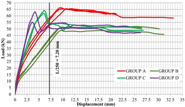
The beams of groups C and D do not have the same tendency in the graph (Figure 6), reaching breaking point at 62.96 kN in group C and 59.10 kN in group D. In these two groups, the breakage of the reinforcement occurred abruptly on one of the extremes of the beams, tearing down with it a portion of concrete with the casted steel sheet, which reached all the way up to the positive reinforcement. These breakages occurred before having reached the admissible displacement limit (L/250).
Images of the beams are shown in Figure 7 to demonstrate the separation of the sheets and the means of breakage during the execution of the tests.
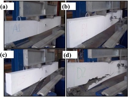
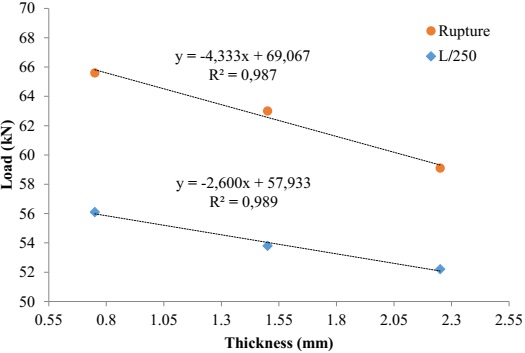
Groups A and B have similar behaviors regarding the emergence of cracks among the central thirds and in the separation of the steel sheet SA 1020 of 0.75 mm. Groups C and D have similar behaviors among them, in relation to the most emphasized cracks, up to the end of the reinforcement and the tearing of the concrete with the sheet up to the bending reinforcement. Considering the non-satisfactory results of groups C and D, a solution could be the introduction of anchoring bolts at the ends of the casted steel sheets SAE 1020, which would help dissipate the accumulation of stress in this region. Figure 8 shows that with the increase of the thickness of the steel sheets SAE 1020, a decrease occurs on the support load of the beams, that is, a decreasing linear behavior.
3.2 Results - 2 nd stage: U-shaped sheets of equal thicknesses.
In the load of the maximum displacement allowed by the standard (L/250), group F has a 20% increase in the average of the values in relation to group E (reference), whereas group G showed an average increase of 16% (Table 5). It is noted that the group reinforced with the profile with the greater longitude (Group F) has greater efficiency when the resistance to reach the displacement is of 7.2 mm.
Table 5 Load at the maximum displacement allowed by the standard (L/250).
| GROUP E | GROUP F (150 cm) | GROUP G (80 cm) | ||||||
|---|---|---|---|---|---|---|---|---|
| Beams | Load (kN) | Arrow (mm) | Beams | Load (kN) | Arrow (mm) | Beams | Load (kN) | Arrow (mm) |
| E1 | 44.2 | 7.2 | F1 | 43.0 | 7.2 | G1 | 53.5 | 7.2 |
| E2 | 46.0 | 7.2 | F2 | 61.1 | 7.2 | G2 | 51.1 | 7.2 |
| E3 | 44.9 | 7.2 | F3 | 57.6 | 7.2 | G3 | 52.6 | 7.2 |
| Average | 45.0 | - | 53.9 | - | 52.4 | - | ||
| Standard deviation | 0.9 | - | 9.6 | - | 1.2 | - | ||
The load necessary to push the beams to their breaking point (Table 6) has a greater load increase when compared to group F (150 cm). This group had a 14% increase in resistance, whereas group G decreased the resistance when compared to group E (reference), with a value of 6%. From Figure 9, it is possible to observe the behavior of each group in terms of the load and the respective displacement.
Table 6 Results of the load and displacements to push the beams to their breaking point.
| GROUP E | GROUP F (150 cm) | GROUP G (80 cm) | ||||||
|---|---|---|---|---|---|---|---|---|
| Beams | Load (kN) | Arrow (mm) | Beams | Load (kN) | Arrow (mm) | Beams | Load (kN) | Arrow (mm) |
| E1 | 63.4 | 23.4 | F1 | 61.0 | 28.7 | G1 | 59.9 | 18.1 |
| E2 | 66.3 | 17.8 | F2 | 82.6 | 13.1 | G2 | 60.4 | 11.9 |
| E3 | 64.3 | 11.4 | F3 | 77.3 | 12.6 | G3 | 61.6 | 8.9 |
| Average | 64.6 | 17.5 | 73.6 | 18.1 | 60.6 | 13.0 | ||
| Standard deviation | 1.5 | 6.0 | 11.3 | 9.2 | 0.9 | 4.7 | ||

The increase in the rigidity of the beam with the addition of the steel sheet is evident. Beam F1 (Figure 10b) behaves differently from the others, as the steel sheet was prematurely separated from the beam, decreasing the increase in stress resistance, and subsequently reaching breaking point with a load of 60.97 kN, not unlike the reference beam of group E. This could possibly be the result of the bad application of the epoxy adhesive, which did not provide a good anchorage of the metal profile to the concrete.

It is possible to note the efficiency of the reinforcement of the beams of group F (beams F2 and F3), with the profile of 150 cm, therefore, the separation of the sheet (Figure 9) also occurs with elevated loads. The beams of group B, with the profile of 80 cm, had a behavior that was inferior to group E (reference group). The average displacements were similar among groups E and F, with an average of 17.8 mm, whereas in group G the average displacement was of 13.0 mm. Beam F1 broke due to bending and the separation of the steel profile, followed by the crushing of the concrete in the central region of the beam. Beams F2 and F3 had cracks due to shear stress as well as breakage due to the separation of the steel profile, with crushing of the concrete at the center of beam F2 and on the region close to the support in beam F3. The analysis carried out on the beams of group G, reinforced with a steel rofile with a longitude of 80 cm, showed that they have a cracking behavior similar to group F: breakage by the separation of the steel profile, given that in beams G1 and G3 the breakage of the concrete was close to the central region, and in beam G2 it was close to the support.
4. Conclusions
Based on the results obtained, it can be concluded that:
The increase in the thickness of the reinforcement with the steel sheet SAE 1020 provided less flexural resistance of the beams, as the sheet thickness of 1.50 mm and 2.25 mm caused the separation of the sheet from the concrete before the normative limit of displacement in L/250 = 7.2 mm. It is worth noting that this fact has certain risks for the implementation of sheets of this thickness. Meanwhile, it could be said that the use of straight sheets with a thickness of 0.75 mm is viable and of quick execution, as there was no need to insert anchorage bolts.
The use of the profile with 150 cm promoted an increase in the flexural resistance, thus with rupture by lateral separation of the sheet with displacements in the upper central spans at 7.20 mm (L/250). The use of the profile with 80 cm was shown to be unviable due to the premature separation of the sheet immediately after reaching the central displacement of 7.20 mm (L250).
In general, it can be said that the use of casted sheets without the use of anchorage bolts is viable when the objective is the immediate increase in the bearing capacity of reinforced concrete beams, in addition to the relative low cost of this reinforcement configuration. Therefore, its efficiency is directly correlated to the anchorage of the sheets to avoid their failure by separation. It is worth noting that the parameters linked to durability, such as the corrosion of the steel sheet and the stability of the epoxy resin, were not taken into consideration in this investigation; however, in a real application such parameters must be rigorously considered, especially in relation to cost/benefit for the effective structural safety.
Referencias
Alfaiate, J., Costa, R. (2004), "O refuerzo de vigas de betão armado com chapas metálicas coladas com resina", Métodos Computacionais em Engenharia, APMTAC, Portugal. pp. 1-13. [ Links ]
Ali, M. S. M., Oehlers, D. J., Bradford, M. A. (2005) "Debonding of steel plates adhesively bonded to the compression faces of RC beams", Construction and Building Materials, V.19, No.6, pp. 413-422. [ Links ]
Associação Brasileira de Normas Técnicas (ABNT). NBR 5739: Concreto - ensaio de compressão de corpos de prova cilíndricos. Rio de Janeiro, 2007. [ Links ]
Associação Brasileira de Normas Técnicas (ABNT). NBR 6118: Projeto de estruturas de concreto. Rio de Janeiro, 2014. [ Links ]
Aykac, S., Kalkan, I., Aykac, B., Karahan, S., Kayar, S. (2013), “Strengthening and Repair of Reinforced Concrete Beams Using External Steel Plates”, Journal of Structural Engineering, V.139, No.6, pp. 929-939. [ Links ]
Campagnolo J. L; Campos Filho A., Silva Filho, L. C. P. (1994), "Técnicas de ancoragem em vigas de concreto armado reforzadas com chapas de acero coladas", In: 36a. REIBRAC - Reunión Anual do Instituto Brasileiro do Concreto, 1994, Porto Alegre/ RS. [ Links ]
Cánovas M. F. (1998), “Patologia e Terapia do Concreto Aramado”, São Paulo: Editora PINI, 522p. [ Links ]
Cánovas, M. F. (1985), "Refuerzo de elementos estructurales de hormigón armado mediante encolado de bandas de acero con adhesivos epoxídicos", Informes de la Construcción, V.37, No. 373, pp. 27-38. [ Links ]
Helene, P. R. L. (2000) "Manual para reparo, refuerzo e proteção de estruturas de concreto", 2 Ed, São Paulo: Editora PINI, 213 p. [ Links ]
Hussain, M. (1995), "Flexural behavior of pre-cracked reinforced concrete beams strengthened externally by steel plates", ACI Structural Journal, V.92, No. 1, pp. 14-23. [ Links ]
Jumaat, M. Z., Alam A. (2008), Experimental and analytical investigations on the structural behaviour of steel plate and CFRP laminate flexurally strengthened reinforced concrete beams", Journal of Applied Sciences, V.8, pp. 4383-4389. [ Links ]
Melo Júnior, L. O. (1997), "Comportamento ao cisalhamento de vigas em concreto armado reforzadas com chapas de acero coladas lateralmente ", Mestrado em Engenharia Civil, Universidade Federal de Pernambuco (UFPE), Recife/PE, 81p. [ Links ]
Narayanamurthy, V., Chen, J. F., Narayanamurthy, J., Cairns, D.J., Oehlers, D.J. (2012) "Plate end debonding in the constant bending moment zone of plated beams", Composites Part B: Engineering, V.43, No. 8, pp. 3361-3373. [ Links ]
Oehlers, D., Moran, J. (1990), "Premature failure of externally plated reinforced concrete beams”, Journal of Structural Engineering, V.116, No. 4, pp. 978-995. [ Links ]
Patiño, A. L. (2005) "Comportamiento mecánico de vigas de hormigón armado reforzadas con bandas encoladas con resinas epoxi", Tesis Ingeniería Civil, Universidad Politécnica de Madrid (UPM), 323p. [ Links ]
Perelles, D. H., Medeiros, M. F., Garcez, M. R. (2013), "Aplicação da análise hierárquica como ferramenta de tomada de decisão para escolha do compósito de refuerzo com polímeros reforçados com fibras", Revista ALCONPAT, V.3, No. 3, pp. 165-180. [ Links ]
Santos, P. M. (2008), "Comparação de refuerzo com chapas de acero e fibras de carbono em vigas de concreto armado submetida à flexión simples", Trabalho de Final de Curso em Engenharia Civil, Universidade Estadual de Feira de Santana (UEFS), Feira de Santana/BA. [ Links ]
Silva Filho L. C. P., Helene P. R. L. (2011), "Análises de estruturas de concreto com problemas de resistência e fissuração", In.: Isaia G. C., Concreto: Ciência e Tecnologia. 1ª Edição. São Paulo: Editora IBRACON, V.2, Cap.32, pp. 1124-1174. [ Links ]
Simões, M. L. F. (2007), "Refuerzo à flexión de vigas de concreto armado por encamisamento parcial", Mestrado em Engenharia Civil, Universidade Federal do Rio de Janeiro (UFRJ), Rio de Janeiro/RJ, 162p. [ Links ]
Souza, V. C. M., Ripper, T. (1988), "Patologia, recuperação e refuerzo de estruturas de concreto", São Paulo: Editora PINI, 255 p. [ Links ]
Tisot, G. D. D. (2010), "Refuerzo à flexión de vigas de concreto armado submetidas a carregamento precoce", Trabalho de Conclusão de Curso em Engenharia Civil, Universidade de Passo Fundo (UPF), Passo Fundo/RS. [ Links ]
Received: November 30, 2015; Accepted: February 20, 2016
 Este é um artigo publicado em acesso aberto sob uma licença Creative Commons
