


 text new page (beta)
 English (pdf)
 Article in xml format
 Article references
 Send this article by e-mail
 Cited by SciELO
  Similars in
SciELO
Similars in
SciELO 
 Permalink
Introduction
Carbon nanotubes (CNTs) are strong and ordered cylindrical structures with one or more concentric walls with interlayers distances from 0.34 to 0.39 nm, diameters in nanometers, and lengths in micrometers [1,2]. The unique properties of CNTs like high surface area [3], electrical conductivity [4,5], thermal and chemical stability [5] have attracted great interest for potential applications as the development of energy storage [3,6] and conversion devices [7] such as supercapacitors [8], Organic Photovoltaic Cells (OPC) [9] and others. Conductive polymer and CNTs are capable of forming clusters due to the strong bonds [10]. CNTs and conductive polymers form composites [11] that increase photo-generated charge transport, obtaining high conversion efficiency, exhibiting higher light absorption and electrical power in OPCs [12].
The main methods used for CNTs synthesis are chemical vapor deposition (CVD), laser ablation, and arc discharge. CVD is a simple method that utilizes hydrocarbon gases as a carbon source and metal catalyst for nanotube growth at temperatures from 500 to 1000 ºC. This method produces high purity CNTs at a large scale but with structural defects [13]. On the other hand, laser ablation and arc discharge methods employ solid-state carbon by vaporizing carbon at temperatures above thousands of degrees Celsius producing high-quality nanotube structures [2]. However, laser ablation is a method that is limited to laboratory scale [13]. The arc discharge is a simple and inexpensive physical method that produces high-quality carbon nanotubes at a large scale [2,13]. CNTs synthesis is carried out vaporizing graphite in an arc discharge, controlling temperature, pressure, voltage, and current. This arc discharge is produced between two graphite bars separated a few millimeters by applying voltages from 10 to 100 V and currents from 1 to 100 A [14-16]. Metallic catalysts such as transition metals (Y, Ni, Co, Fe), metallic oxides (Y2O3, Al2O3), and metal mixtures (Ni/Y, Ni/Fe, Fe/Co) are used for the growth of CNTs [16-18].
CNTs synthesis produce samples significantly contaminated by amorphous carbon and metallic impurities [19-21]. These impurities interfere with the properties, characterization, and applications of CNTs [22]. Metal-doped CNTs are specially required in electronic devices and the electrocatalysis process. [23,24]. However, pure CNTs are needed in water purification technologies, optoelectronics, biosensors, fuel cells, electrode arrays, drug delivery, and others [25-27]. Therefore, acid treatment is necessary to eliminate metallic impurities [19-21]. HCl, HNO3, and H2SO4 acids are commonly used to dissolve exposed metallic particles on CNTs [21]. Sharma et al. synthesized MWCNTs by the arc discharge method varying current in the range from 50 to 200 A [9]. On the other hand, Raniszewki et al. produced MWCNTs by electric arc method with metal catalysts observing that the carbon element flux changed significantly [28]. Roslan et al. obtained nanotubes through an arc discharge at a voltage of 12 V, a current of 70 A, and in the presence of magnetic fields obtaining straight MWCNTs [29]. Yermagambet et al. vaporized graphite by arc discharge method at a constant voltage of 50 V and currents of 120, 150, 170 and 200 A in an inert argon atmosphere obtaining CNTs with diameters from 58 to 370 nm [30].
In this paper, CNTs were synthesized by vaporizing graphite rods applying an arc discharge in the presence of powdered metallic Ni or Ni/Y mixture acting as catalysts. An average voltage and a peak current used during the arc discharge generation were 30 V and 95 A. Hydrochloric acid (HCl) was used to remove metallic residues from the obtained CNTs. An ultrasonic bath was used for 60 minutes to disperse the amorphous carbon clusters. CNTs were characterized using scanning electron microscopy, transmission electron microscopy, Fourier transform infrared spectroscopy and ultraviolet-visible spectroscopy. Scanning electron microscopy is a technique that generates a high-resolution 3D image of the product providing morphological and compositional information [9,31]. It allowed us to observe clusters of multi-walled carbon nanotubes (MWCNTs) with amorphous carbon particles attached to the surface of the nanotubes. Transmission electron microscopy is a technique that reveals the internal structure of the nanotubes [32]. It corroborated outer and inner diameters of 24 nm and 5 nm, respectively, and an interlayer distance of 0.4 nm. The bands at
Experimental
Experimental device
The CNT synthesis system makes use of the arc discharge method and is shown in Fig. 1. A cylindrical reactor of 100 mm diameter was implemented employing a glass tube-like chamber, sealed at both extremes with polyamide covers. A stainless-steel electrode-holder, an Ar gas inlet valve, and a pressure sensor coupling were attached to the top cover. A mobile electrode-holder and a vacuum pump coupling were installed on the bottom cover [33]. The upper electrode-holder supported a 7 mm diameter graphite rod as the cathode, and the lower electrode-holder supported a 9 mm diameter graphite rod serving as the anode. A 3 mm wide and 3 mm deep hole was drilled into the tip of the anode and was filled with either Ni or a Ni/Y mixture serving as catalysts.

The CNTs synthesis was studied with and without the use of catalysts. Ni (99.99 %) and Y (99.5 %) were purchased from Aldrich-Sigma. As catalyst, 5 % wt. Ni was mixed with 95 % wt. graphite powder. Also, 2 % wt. Ni and 4 % wt. Y were mixed with 94 % wt. graphite. Both Ni and Ni/Y were grinded with an agate mortar and sieved with a mesh of 75 μm. CNTs synthesis was performed in an inert atmosphere introducing an Ar flow of 1.43 cm3/min monitored by FMA1700A mass flowmeter, applying a pressure of 39 kPa generated by Adixen Pascal 2005 SD vacuum pump and measured with an MKS Pirani 901 P pressure sensor. These conditions allow generating a stable plasma within the chamber [33].
CNTs synthesis by arc discharge
The arc discharge was generated by using a DC power supply and biasing both electrodes at an average voltage of 32.5 V monitored by Tektronix TBS-1102B-EDU oscilloscope. A peak current of 99 A was applied measured by Tektronix PG0 15 A current probe [33]. The arc discharge was ignited and controlled by keeping a gap distance of 1 mm between the two electrodes, which was controlled by anode movement using a vertical displacement mechanism consisting of an endless shaft coupled to a NEMA 23 stepper motor that is connected to an Arduino© UNO microcontroller. CNTs were collected after arc discharge formation following chemical treatment with HCl solution at 1 M (Golden Bell 38 %) to remove metallic impurities from remaining catalysts. Subsequently, CNTs were sonicated in a Cole-Parmer ultrasonic bath for 60 minutes to disperse amorphous carbon clusters; then, CNTs were decanted and washed with deionized water. Finally, the CNTs were dried at 70 °C in a Thermolyne furnace for 24 hours.
Characterization
Morphology was determined by the JEOL JSM-6610LV scanning electron microscope (SEM). The CNTs samples were coated with gold and supported on a carbon adhesive tape. Moreover, the elemental composition was obtained employing an X-ray energy dispersion spectrometer (EDS) at a working voltage of 20 kV. Also, the morphology of CNTs was obtained by the JEM 2010HT transmission electron microscope (TEM) taking a drop of CNTs diluted in isopropyl alcohol supported on a 2-mm diameter copper grid. Functional groups of CNTs were identified using a Varian 640-IR spectrophotometer in the range from
Results and discussion
CNTs synthesis
Fig. 2(a) shows the electrical signals measured between the polarized electrodes before arc discharge ignition with an average voltage of 33.5 V and an average current of 92.5 A. Both electrical waveforms were in phase. During the arc discharge generation (Fig. 2(b)), the electrical waveforms presented an average voltage of 30 V and an average current of 75 A with a peak current of 95 A. During the arc discharge, the demanded electric power was calculated at 2.25 kW by multiplying the average voltage and the average current.

The arc discharge formation during CNTs synthesis is shown in Fig. 3(a). After the arc discharge formation, the cylindrical reactor presented carbon powder deposits inside the chamber and both electrodes. The appearance of a collar on the anode was also observed (Fig. 3(b)) [16]. These deposits were due to the intensive vaporization that arc discharge submits to each electrode. Carbon powder (Fig. 3(c)) collected from the reactor presented a refined appearance [34] due to the carbon sublimation-deposition process.

Study of the Morphology of CNTs using SEM and TEM
Graphite was vaporized without catalysts, and in the presence of Ni and a Ni/Y mixture applying the arc discharge method following chemical treatment with HCl at 1 M. The SEM micrographs of carbon powder synthesized without catalysts (Fig. 4(a)) revealed a morphology based on carbon nanoparticle clusters. Likewise, the morphology of carbon powder synthesized in the presence of 5 % wt. Ni (Fig. 4(b)) presented elongated and straight nanotubes attached to amorphous carbon particles. In contrast, the morphology of carbon powder synthesized in the presence of 2 % Ni/4 % Y wt. (Fig. 4(c)) exhibited shortened and curved nanotubes adhered to amorphous carbon particles. The morphology observed in both samples of carbon powder synthesized in the presence of metallic catalysts presented the typical feature of nanotubes produced applying the arc discharge method [16,34].
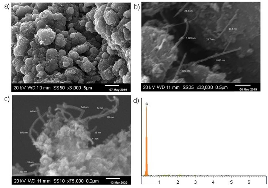
Fig. 4 SEM determined morphology of CNTs obtained (a) without catalysts, (b) 5% wt. Ni, (c) 2 % Ni/4 % Y wt., (d) Elemental composition with 2 % Ni/4 % Y wt. by EDS.
In the morphology of CNTs synthesized with Ni (Fig. 4(b)), an average outer diameter of 24 nm and variable lengths from 690 to 1680 nm were identified. Similarly, in the morphology of CNTs synthesized with a 2 % Ni/4 % Y wt. mixture (Fig. 4(c)) an outer average diameter of 34 nm and variable lengths from 350 to 880 nm were identified. Similar measurements of CNTs were reported in the other works [35-37]. EDS analysis was applied at CNTs synthesized with a 2 % Ni/4 % Y mixture because it increased nanotube production. The EDS spectrum of CNTs (Fig. 4(d)) indicated a peak at 0.3 keV, which pointed out that the elemental composition was 100 % carbon observing the absence of metallic impurities. Likewise, the lack of Cl was observed due to the washing of the carbon powder with deionized water. Nevertheless, the presence of H cannot be determined by means of EDS due to the limitations of the technique.
The morphology obtained using the TEM technique (Fig. 5(a-c)) of the CNTs synthesized in the presence of a 2 % Ni/4 % Y wt. mixture revealed that the CNTs have a great number of layers and are therefore properly described as multiple-wall carbon nanotubes (MWCNTs) with amorphous carbon particles attached to the surface of the nanotubes; this morphology was previously observed in other works [9,38]. Carbon nanoparticles confined inside CNTs by the effect of the arc discharge were also detected and informed previously in other work [38]. The measurement of outer and inner diameters and interlayers distance of MWCNTs was realized (Fig 5(a-c)). A MWCNTs cluster presented an average outer diameter of 24.6 nm. Also, in two nanotubes next to an amorphous carbon particle (Fig. 5(b), the average outer diameter was 23.24 nm. Moreover, in two nanotubes with some amorphous carbon particles adhered to one of them (Fig. 5(c)), the average outer diameter was 19 nm. Meanwhile, the average inner diameter of 5 nm was measured for MWCNTs on different section-samples (Fig. 5(a-d)). The outer and inner diameters of the MWCNTs were like the reported in some other studies [38-40]. The average interlayer distance in the MWCNTs (Fig. 5(d)) was 0.4 nm, that is similar to values reported in other studies [35,40]. Finally, the TEM and SEM derived average diameter of the MWCNTs were in the nanometric scale.

FT-IR spectroscopy
Functional groups identification utilizing FT-IR spectroscopy, without-vaporized graphite powder and MWCNTs powder produced by arc discharge method in the presence of a 2 % Ni/4 % Y wt. mixture following chemical treatment with HCl at 1 M, are shown in Fig. 6. There are no significant absorption bands in the spectrum of the without-catalyst vaporized graphite [41]. Meanwhile, in the MWCNTs spectrum some functional groups adhered to the structure of MWCNTs were identified; some peaks were located at

UV-Vis spectroscopy
UV-Vis electromagnetic absorbance of MWCNTs produced by the arc discharge method following chemical treatment with HCl at 1 M is presented in Fig. 7. The UV-Vis spectrum of MWCNTs shows two absorbance bands at 204 and 256 nm corresponding to sp2 hybridization, inside the range from 310 to 155 nm associated with the π plasmon [42]. The sp2 hybridization was identified with the typical π-π* electron transitions in the SWCNTs and MWCNTs [43]. Moreover, the absorbance band at 256 nm, located inside the range from 253 to 260 nm corresponds to the characteristic absorbance band of MWCNTs [44, 45]. Another absorbance band was located at 562 nm inside the range from 440 to 645 nm, which indicates transitions of metallic CNTs [42]. After this absorbance band, the spectrum of CNTs remains practically constant.

Conclusion
MWCNTs were obtained by the arc discharge method by applying an average voltage of 30 V and a peak current of 95 A, which required an electrical power of 2.25 kW. The glass chamber of the reactor allowed observing the process of synthesis during the arc discharge and the carbon powder deposits at the end of the discharge. The morphology observed by the SEM technique showed elongated and straight MWCNTs with Ni and shortened and curved MWCNTs with a 2 % Ni/4 % Y wt. mixture. All MWCNTs were detached from amorphous carbon particles. The yield of MWCNTs significantly increased employing metal catalysts such as Ni and Ni/Y mixture at a pressure of 39 kPa under an atmosphere of Ar. The morphology determined by the TEM technique showed MWCNTs with similar diameter measurements obtained by SEM. The results of EDS spectra revealed that the MWCNTs synthesized after chemical treatment with HCl at 1 M had low impurity contents.
The functional groups detected by FT-IR spectroscopy presented some bands characteristic for MWCNTs. Besides, the FT-IR spectra verified the functionalization of the nanotubes with different functional group. The binding of these groups to the surface of MWCNTs may tune the properties of the nanotubes and enable diversified applications of CNTs, such as in the development of energy storage and conversion devices. UV-Vis electromagnetic absorbance exhibited the properties of sp2 hybridization related to the π-π* transitions in the MWCNTs. Due to this nature, MWCNTs synthesized with the arc discharge method employing metal catalysts could form composites with conducting polymers used in developing of OPCs as working electrodes.

