


 text new page (beta)
 English (pdf)
 Article in xml format
 Article references
 Send this article by e-mail
 Cited by SciELO
  Similars in
SciELO
Similars in
SciELO 
 Permalink
1. Introduction
Doubly fed induction generators (DFIGs) are most popular for wind energy, as they have high effectiveness Djerriri (2020), Djilali et al. (2020). Jazaeri et al. (2012), Mondal et al. (2020). The DFIG based wind turbines (DFIG-WTs), a typically employed wind power generation system, have been widely used to achieve the maximum energy conversion, smaller capacity of energy electronic devices and full controllability of reactive, and active powers of the DFIG-WT Phan et al. (2015), due to their performances such as varying speed operation. The rotor of the DFIG is fed via a rotor side inverter (RSI), while the stator circuit is connected to the grid directly Rodarte Gutierrez et al. (2021). On the other hand, many strategies have been designed for controlling the rotor converter of the DFIG-WT. In Amrane et al. (2016), the vector method (VM) strategy is the most popular method used in the command of the rotor converter for DFIG-WT. This technique is based on the SVO method (Stator Voltage Orientation) Muller et al. (2002) or an SFO method (Stator Flux Orientation) Xu and Cheng (1995). In the VC strategy, proportional-integral (PI) are used to regulate the reactive/active power of the DFIG-WT. Besides, the VM technique need accurate values of DFIG-WT parameters and rotor speed. This method gives a large THD value for the rotor/stator voltage Benbouhenni and Bizon (2021a).
To minimize the THD of the DFIG, direct flux and torque command (DFTC) have been presented in Chen et al. (2010), El Ouanjli et al. (2019), Farajpour et al. (2020). In the classical DFTC method, torque and rotor flux can be regulated by using two hysteresis controllers and lookup tables. However, direct torque technique is a robust algorithm and simple structure relative to VM strategy. This technique minimizes the THD value compared to vector command and has a good dynamic response. Similar to the DFTC strategy, a direct reactive/active power command (DRAPC) of DFIG-WT was recently proposed Izanlo et al. (2017), Jou et al. (2009), Mirzakhani et al. (2018). The basic principle of the DRAPC command was proposed by Noguchi in 1998. In the DRAPC strategy, the active and reactive powers replace the torque and rotor flux amplitude used as a controlled output in the DFTC method.In addition, the reactive and active powers can be regulated by using a lookup table and two hysteresis controllers. Also, the DRAPC technique is an easy, robust and simple method relative to the VM strategy. The DRAPC technique gives a good dynamic response and reduces the reactive and active powers ripples of the DFIG-WT. In Shehata et al. (2013), an improved DRAPC method of wind turbine driven DFIGs was presented. In Zhi and Xu (2007), the DRAPC method was proposed based on the stator flux orientation technique to reduces torque and active power undulations. In Benbouhenni (2019), a novel DRAPC strategy was designed based on the neural network algorithm and five-level inverter, where the lookup table is replaced by a neural algorithm. In Mossa et al. (2020), active/reactive powers PI controllers and classical space vector pulse width modulation (SVPWM) strategy were combined to replace the hysteresis comparators. In Bouyekni et al. (2018), the DRAPC strategy based on a high sliding mode controller (HSMC) has been designed. In Xu et al. (2006), a DRAPC technique was proposed to command the DFIG without using a rotor position sensor. In Benbouhenni et al. (2018), a DRAPC technique was proposed using twelve sectors and neural algorithms. In Benbouhenni (2020a), two neural hysteresis comparators were proposed to minimize the active power and torque undulations of DFIG-WT controlled by the DRAPC method. In Benbouhenni et al. (2021), a novel DPC technique was proposed based on the neural HSMCmethod, where a PI of DRAPC with SVPWM technique was replaced by the NHSMC algorithm. However, this technique is simple and gives minimum power ripples compared to the conventional DRAPC method. In Benbouhenni et al. (2020), the author designs a novel DPC technique based on the neuro-fuzzy HSMC (NF-HSMC) algorithm to command DFIG-WT.
In this work, the neural DPC technique with the application of the four-level NSVPWM technique has been proposed. The original contribution of this work is the application of the four-level NSVPWM strategy in the neural DPC control scheme with DFIG-based dual-rotor wind turbine (DRWT) and performance investigation of this new control method (called below as NDPC-4L-NSVPWM).
The novelty and main contributions of this work are as follows:
1) proposal of a new direct power control method of the DFIG-DRWT using neural PI controllers and four-level neural space vector PWM technique (NDPC-4L-NSVPWM).
2) application of the NDPC-4L-NSVPWM control method with DFIG-based dual-rotor wind power (DRWP).
3) comparative performance analysis of the proposed method based on new performance indicators for the reference tracking test (RTT) and the robustness test (RT).
4) comparative investigation of the performance of the NDPC-4L-NSVPWM control method with other control method proposed in the literature.
This paper is divided into 4 Sections. In Section 1, the introduction is presented. The mathematical model of the DFIG, the DPC technique with PI controllers, the description of the four-level NSVPWM technique and the NDPC-4L-NSVPWM control method are presented in Section 2. Simulation studies are presented and discussed in Section 3 and 4. The paper is concluded with a summary.
2. Material and methods
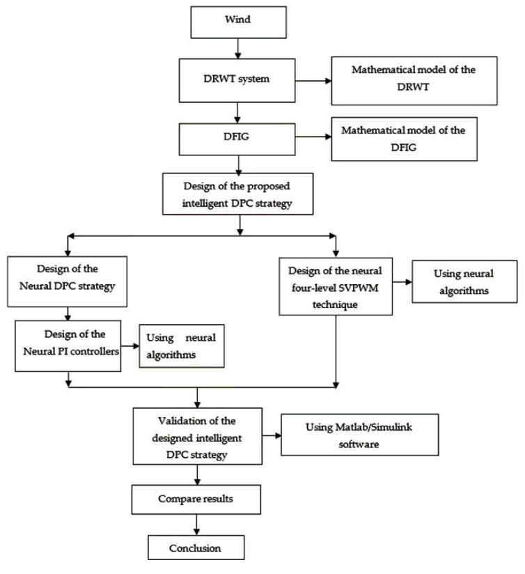
In order to simply highlight the proposed idea, a scheme representing the design and implementation stages is presented in Figure 1. It is worth mentioning that the designed DPC method is very simple and uncomplicated, being easily implemented based on the use of neural networks both at the level of the SVPWM controller and the PI controller to obtain a more robust DPC method. Neural networks were used in this paper due to the higher speed and accuracy of response compared to other methods, such as fuzzy logic.
2.1. Mathematical model of the DFIG
In order to generate energy from wind, we need a generator and a turbine. The latter converts wind power into mechanical power in order to rotate the generator and thus produce electric current. In this work, a DRWT was used, and this is because of its efficiency compared to a single-rotor, and also because of the value of the torque generated by it.
This turbine has been studied in several scientific works Luo and Niu (2017), Wang et al. (2019), Yahdou et al. (2020), Zhao et al. (2015). On the other hand, the mathematical model of three-phase DFIG has been formulated based on commonly used simplifying assumptions presented in detail in Zhao et al. (2015), Ayrir et al. (2020).
The fluxes equations are given as follows:
Equation (2) represents the direct and quadrature rotor/stator voltages of the DFIG.
Equation (3) represents the mechanical equation of the DFIG.
And:
Equation (5) represents the reactive/active power of the DFIG.
There are several methods used to control generators such as FOC, DTC and DPC. Each method has advantages, performances and disadvantages. In Table 1, The characteristics of the most frequently used methods are summarized. Through this table, it was noticed that the DPC strategy is among the methods that have good properties, and this is noticed through the frequent use of control, especially in the field of wind energy.
Table 1 A comparative study between the different methods used in the control of DFIG.
| DTC control | FOC strategy | Direct vector control | DRAPC strategy | Indirect vector control | Backstepping control | |
| Simplicity | Simple | Rather complicated | Simple | Simple | Rather complicated | Complicated |
| Quality of current | Acceptable | Weak | Weak | Acceptable | Weak | Good |
| THD | Medium | High | High | Medium | High | Medium |
| Dynamic response | Fast | Slow | Slow | Fast | Slow | Fast |
| Experimentation | Easy | Difficult | Easy | Easy | Difficult | Difficult |
| Controller | Hysteresis controller | PI controller | PI controller | Hysteresis controller | PI controller | - |
| Control of inverter | Switching table | PWM | PWM | Switching table | PWM | PWM |
| Robustness | Robust | Not robust | Not robust | Robust | Not robust | Robust |
2.2. DPC strategy with PI controllers
The DPC-PI goal is to command the active and reactive powers of the DFIG-DRWT. In this control, reactive power is regulated using the direct axis voltage Vdr*, while the active power is regulated using the quadrature axis voltage Vqr*. This strategy is detailed in Yousefi-Talouki et al. (2019). The main advantages of the DPC-PI with the 2-level SVPWM strategy are its good dynamic response, constant switching frequency operation, and simple algorithm Mekkaoui et al. (2017). But this technique determines a high value for THD of the voltage and more powers ondulations of the DFIG-DRWT. In addition, this method is less durable, and this is due to the use of PI regulators.
As it is known, this method depends mainly on the classical DPC method or in another way is a development of the DPC technique. In this method, hysteresis comparators and switching table of classical DPC strategy are changed by PI controllers and SVM technique, respectively.
The proposed DPC-PI with SVPWM, which is proposed to reducer active and active power undulations of the DFIG-based DRWT system, is shown in Figure 2. In this technique, reactive and active powers are controlled by using two PI controllers. On the other hand, the generator inverter is controlled by the two-level SVPWM technique.

The components of flux can be estimated by Kulothungan et al. (2019):
The rotor flux is given by:
where:
Equation (9) represents the rotor angle of rotor flux:
Reactive and active powers are calculated using (10) and (11):
The use of the classical SVPWM technique offers several advantages, among which we can mention the minimization of the THD value of the current and the fact that the output voltage is 80% higher compared to the PWM technique. But this method is relatively difficult to implement because it is based on complicated control schemes that uses the calculation of the sector and the angle Kulothungan et al. (2019). In Benbouhenni (2020b), the author proposes a new SVPWM strategy of 2-level converter based on Min and Max of the 3-phase voltages. This designed strategy is easy to implement, as it is based on a simple algorithm and an uncomplicated technique compared to the SVPWM scheme. This technique is detailed in Benbouhenni and Bizon (2021b, 2021c). The two-level SVPWM technique proposed to command the two-level converter is illustrated in Figure 3.
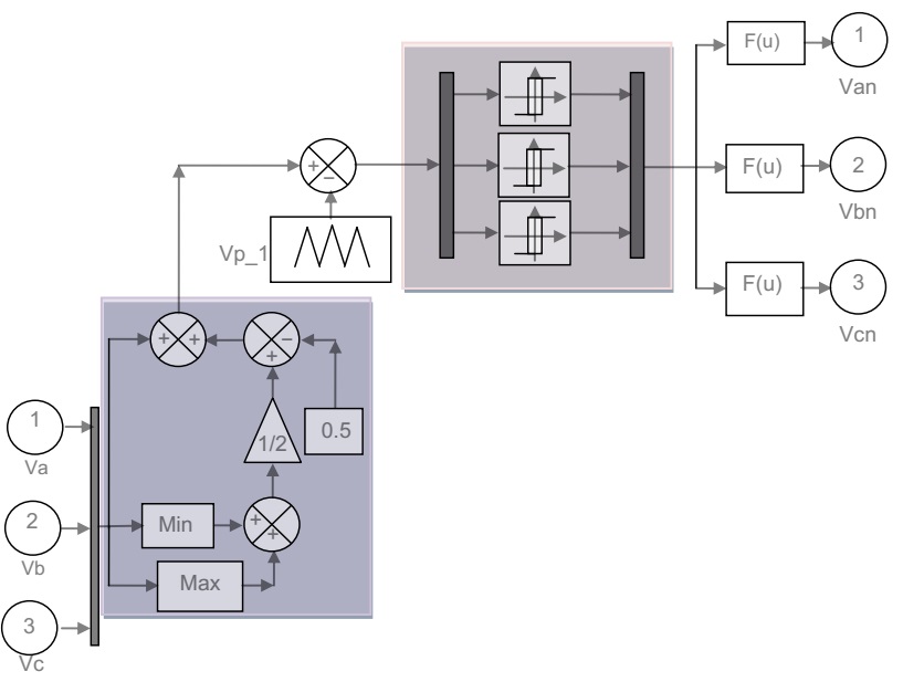
Table 2 presents a comparative study between the traditional SVM and SVM proposed in Benbouhenni (2020b). It can be said from this table, that the designed SVM technique in Benbouhenni (2020b) is a better method than the classical SVM method in terms of cost of implementation, speed of response, energy consumption and THD value. Therefore, this principle is used here for controlling a four-level inverter. Next subsectionof this paper explains the proposed neural SVPWM (NSVPWM) method for controlling a four-level inverter for an asynchronous generator (DFIG).
Table 2 Comparative study between the traditional SVM and the proposed SVM in Benbouhenni (2020b).
| Traditional SVM | Proposed SVM in Benbouhenni (2020b) | |
|---|---|---|
| Simplicity | Complicated | Simple |
| Implementation | Complicated | Easy |
| Applied to multi-level inverter | Difficult | Easily |
| Robustness | Robust | Robust |
| Calculate of the sector and angle | Yes | No |
| Dynamic response | Slow | Fast |
| Energy | High | Low |
| Circuit size | Big | Small |
| Completion cost | Expensive | Not expensive |
| THD | Medium | Medium |
2.3. Four-level neural SVPWM technique
In this paper, it is suggested to use a four-level inverter for the generator rotor feeding instead of using a classic inverter in order to obtain better results. The SVPWM technique was chosen for the control of the four-level NPC inverter due to its simplicity and ease of implementation. The block diagram of the designed SVPWM technique for four-level NPC inverter is shown in Figure 4.
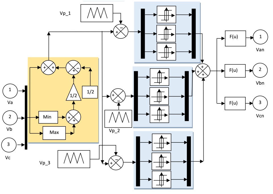
Through this figure, we note that this method is very simple, uncomplicated and can be accomplished easily. This method is preferable in the case of a multi-level inverter. Theprincipal disadvantage of the SVPWM strategy is that the THD value of voltages/currents is high.
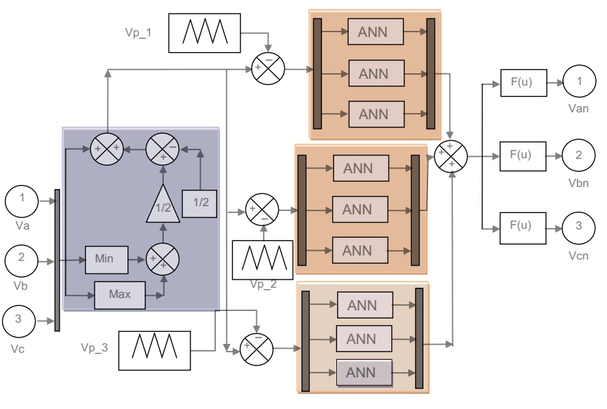
To overcome the problems of the traditional four-level SVPWM strategy, the ANN algorithms are designed and used in this study to command the rotor converter of DFIG-DRWT. However, the ANN method has found many applications such as command AC machines.The ANN algorithm contains an output layer, input layer, and hidden layer Madvar et al. (2020). The ANN controller is a method based on observations and engineering experience. In neural techniques, we do not need the mathematical model of the systems compared with another classical strategy. The design of a four-level SVPWM strategy that incorporates the neural method allows minimizing the THD value, increasing robustness and reducing the ripples of DFIG-DRWT powers.
On the other hand, unlike the classical method, this proposed method is less expensive and therefore can be easily accomplished (criteria that are decisive in choosing a control method).
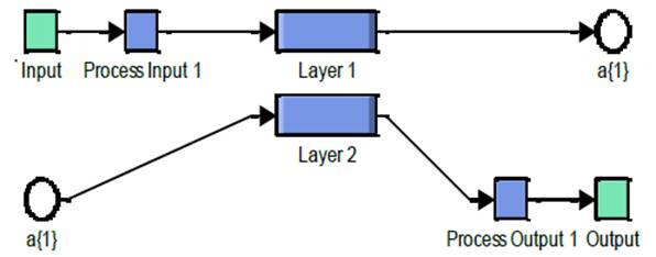
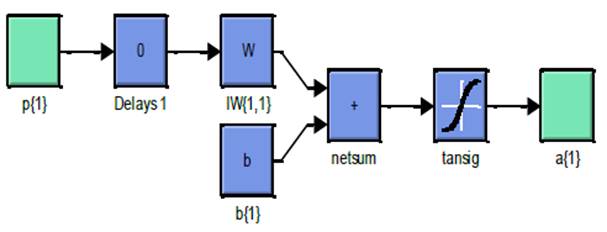
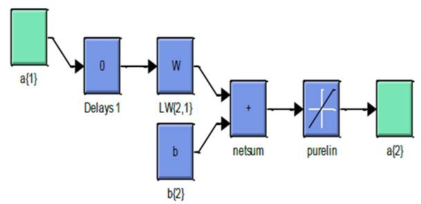
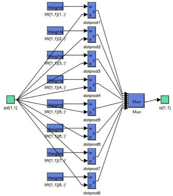
In the four-level neural SVPWM strategy, the training used is that of the Levenberg-Marquardt (LM) algorithm. The parameters of the LM algorithm are shown in Table 3. The structure of the ANN algorithm is shown in Figure 6. In addition, the structure of layer 1 and layer 2 is shown in Figure 7 and Figure 8, respectively.
Table 3 Parameters of the LM algorithm
| Parameters of the LM algorithm | Values |
|---|---|
| Functions of activation | Tensing, Purling, Gensim |
| Number of neurons of input layer | 1 |
| Train Param.Lr | 0.02 |
| Train Param.eposh | 300 |
| Number of neurons of hidden layer | 8 |
| Train Param.show | 50 |
| Coeff of acceleration of convergence(mc) | 0.9 |
| Train Param.mu | 0.9 |
| Number of hidden layers | 1 |
| Number of neurons of output layer | 1 |
| TrainParam.goal | 0 |
The method proposed in this section is used to better control a 4-level NPC inverter of the DFIG-DRWT system. Due to the use of the neural PI controller, a more robust method is obtained, thus reducing current and active power fluctuations.
2.4. Neural DPC strategy with four-level NSVPWM technique
The operating diagram of the neural DPC with four-level NSVPWM strategy (NDPC-4L-NSVPWM) is presented in Figure 9.

The novelty and difference compared to DPC-PI strategy is using of the four-level NSVPWM technique to replace the classical SVPWM technique and neural controllers to replace the classical PI controllers. This designed command technique is a robust algorithm and easy to implement. The main advantages of neural DPC with 4L-NSVPWM technique are its good dynamic response, simple algorithm, and constant switching frequency operation. Also, this strategy gives minimum powers undulations and THD of rotor voltage of the DFIG-DRWT compared to the vector control and DPC-PI strategy.
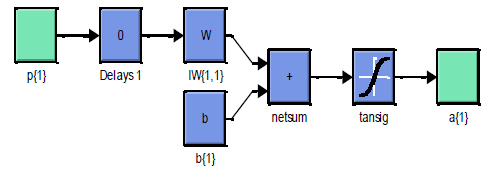
In neural PI controller, the training used is that of the retro-propagation of LM algorithm. The components of the LM method are shown in Table 4. The structure of the ANN controller is shown in Figure 10. On the other hand, the structure of the layer 1, layer 2 and hidden layer is shown in Figure 11, Figure 12 and Figure 13 respectively.
Table 4 Characteristics of the retro-propagation.
| Parameters of the LM | Values |
|---|---|
| Train Param.eposh | 1000 |
| TrainParam.Lr | 0.005 |
| Train Param.show | 50 |
| Number of input layer | 1 |
| Train Param.goal | 0 |
| Number of output layer | 1 |
| Train Param.mu | 0.9 |
| Coeff of acceleration of convergence (mc) | 0.9 |
| Number of hidden layers | 1 |
| Functions of activation | Tensing, Purling, Gensim |
| Number of neurons of hidden layer | 8 |


3. Results
Numerical simulations for the validation of strategies designed for a DFIG-DRWT have been performed in Matlab.The parameters of machine are those mentioned in Benbouhenni and Bizon (2021b), (2021c) and presented in Annex A1. The parameters of the PI regulators of the reactive and active powers as shown in Table 5. Both methods will be tested and compared in two different tests: reference tracking and robustness tests.
A. The first test
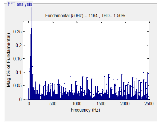
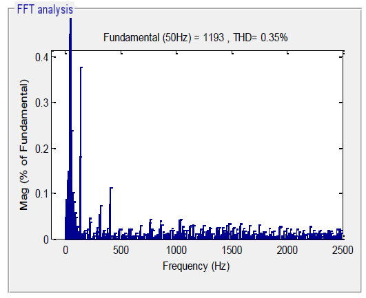
The first test(T1) is the reference tracking test. The goal is to find out which method provides better results in terms of reference tracking. Also, in terms of ripple value and THD value. By using simulation, the results are shown in the Figures 14 to 23. Figures 18-19 show the THD value of current for both strategies of DFIG-DRWT. Note that the THD value is reduced for NDPC-4L-NSVPWM when compared to DPC-PI technique (Table 6). Through this table, we find that the proposed NDPC-4L-NSVPWM strategy minimized the THD value of stator current by about 76.66% compared to the DPC-PI technique.

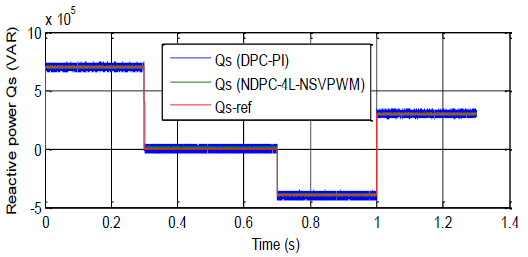


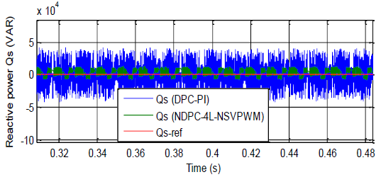


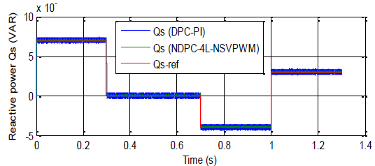
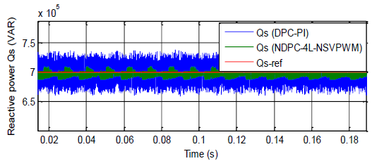
The simulation signal of the measured and reference reactive power of the DFIG-DRWT are shown in Figure 15 in order to compare the characteristics of the NDPC strategy with application of the 4L-NSVPWM technique with the characteristics of the conventional DPC-PI strategy. The reactive power track well their reference value (Qs-ref). The designed technique give minimum the oscillations of the reactive power relative to the classical DPC with PI controllers (Figure 21).
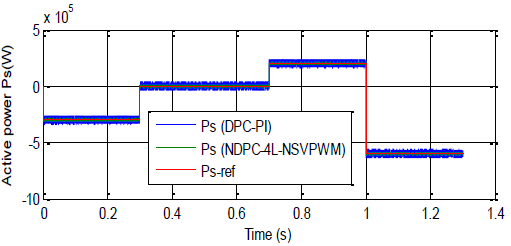
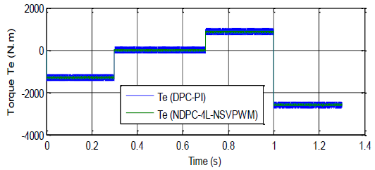
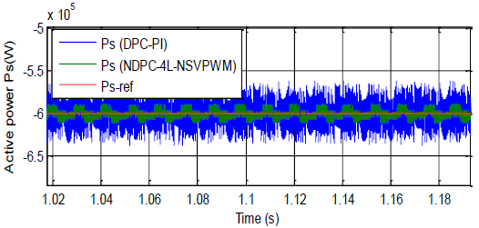
For both strategies, the active power track well their reference value (see Figure 14). Moreover, the DPC-4L-NSVPWM strategy reduced the active power ripple relative to the DPC-PI (Figure 20).
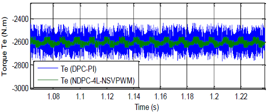
The simulation waveforms of the measured torque of the three-phase DFIG are presented in Figure 16 to compare the characteristics and effectiveness of the NDPC technique using the 4L-NSVPWM technique with those obtained using the DPC-PI strategy. The NDPC-4L-NSVPWM method reduces the torque ripple in comparison with the DPC-PI technique (Figure 22).
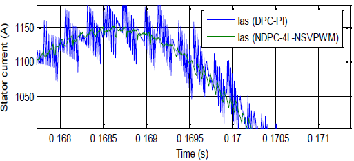
The shape of the current (Ias) is presented in Figure 17. It is observed that the amplitudes of Ias depend on the value of the DFIG-DRWT load. Note that the NDPC-4L-NSVPWM method minimized the current oscillations relative to the DPC-PI technique (Figure 23).
Table 7 shows the values of the response time for the active power and electromagnetic torque of both DPC strategies. From this table, we not that the NDPC strategy with 4L-NSVPWM technique is the best in terms reduce of the response time (less time). Through these results, it is noted that the proposed NDPC-4L-NSVPWM technique minimized the value of the time response for each of the torque and active power about 29% and 31.5%, respectively, compared to the DPC-PI technique.
Table 7 Comparative analysis of response time.
| Response time (ms) | ||
|---|---|---|
| DPC-PI | NDPC-4L-NSVPWM | |
| Active power | 0.200 | 0.137 |
| Torque | 0.200 | 0.142 |
The zoom in the active power, reactive power, torque and stator current is shown in Figures 20 to 23, respectively. It can be seen that the NDPC strategy with 4L-NSVPWM technique reduced the oscillations in active power, reactive power, torque and stator current relative to the DPC with PI controllers.
The results of the first test are summarized in Table 8. Table 8 represents a comparative study between the DPC-PI strategy and the proposed strategy in terms of response time, reference tracking, effective power ripple value, THD value, etc. Through this table, it is concluded that the designed strategy is much better than the DPC-PI strategy. The designed strategy improved the efficiency and features of the machine such as setting time and time response.
Table 8 Comparative results obtained from the designed.
| Criteria | Control strategies | |
|---|---|---|
| DPC-PI | NDPC-4L-NSVPWM | |
| Reference power tracking | Acceptable | Very good |
| THD (%) | 1.50 | 0.35 |
| Power ripples | High | Low |
| Time response (s) | Medium | Low |
| Qs: ripples (VAR) | About 80000 | About 1200 |
| Te: ripple (N.m) | About 300 | About 20 |
| Settling time (ms) | Medium | Low |
| Overshoot (%) | ≈ 24% | ≈ 1.3% |
| Robustness | Medium | High |
| Ps: ripples (W) | About 75000 | About 1350 |
| Converter and filter design | Simple | Simple |
| Rise time (s) | Medium | Low |
| Ias: ripple (A) | About 80 | About 20 |
| Algorithm complexity | Simple | Simple |
| Dynamic performance | Slow | Fast |
| Quality of the current/power generated | Acceptable | Excellent |
B. The second test
The second test (T2) is the robustness test. In this test, the values used in the first test for the Rr and Rs are multiplied by 2, and the values for the Lr and Ls are multiplied by 0.5, where Rr and R_s are the resistances, and Lr and Ls are the inductance of the stator and rotor windings mentioned in Annex A1. Simulation results are presented in Figures 24-33. As it’s shown by these figures, the reactive and active power tracks well their reference values (see Figure 26-27). Figures 28 and 29 show the torque and current, respectively. From this figures, torque and current deponds the system and load active power. In addition, these variations present an apparent effect on reactive power, torque, active power and currents curves such as the effect appears more significant for the DPC-PI strategy relative to NDPC-4L-NSVPWM (see Figures 30-33).
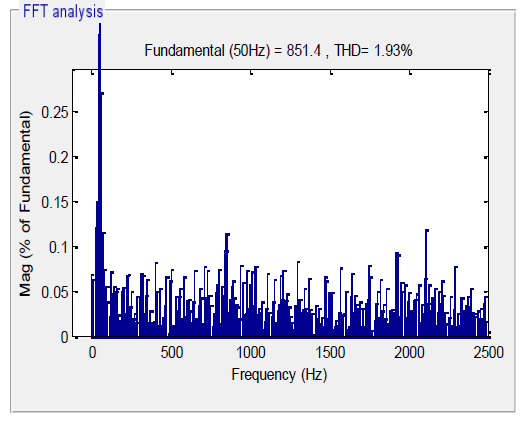


The THD of current in the NDPC-4L-NSVPWM technique has been reduced significantly (Figures 24-25). Table 9 shows the THD values of both strategies. Through this table, we find that the proposed NDPC-4L-NSVPWM technique reduced the THD value by about 79.27% compared to the DPC-PI technique. Based on the results presented here, it can be concluded that the designed NDPC-4L-NSVPWM strategy is more robust than the traditional DPC-PI method.
A comparative study between the designed NDPC-4L-NSVPWM in this work with some published works in terms of the value of THD is shown in Table 10. Through this table, we notice that this NDPC-4L-NSVPWM technique gave for the THD of the current a better value compared to other control methods.
Table 10 Comparison of the obtained results with those reported in reference control schemes proposed in the literature
| References | Strategies | THD (%) |
|---|---|---|
| Boudjema et al. (2017) | Direct torque control | 2.57 |
| DTC-SOCSM strategy | 0.98 | |
| Jbarah and Andrey (2021) | DTC-PI strategy | 0.63 |
| Ayrir et al. (2020) | DTC strategy | 6.70 |
| Fuzzy DTC strategy | 2.04 | |
| Boudjema et al. (2013) | Fuzzy sliding mode controller technique | 3.1 |
| Yaichi et al. (2019) | DPC with STA algorithm | 1.66 |
| Amran and Chaiba (2016) | FOC strategy | 3.70 |
| Alhato and Bouallègue (2019) | DPC control using L-filter | 10.79 |
| DPC control using LCL-filter | 4.05 | |
| Quan et al. (2019) | Integral SMC technique | 9.7 |
| Multi-resonant-based SMC | 3.2 | |
| Boudjema et al. (2016) | SOSMC method | 3.13 |
| Jbarah and Mazalov (2021) | DTC-PI strategy | 0.88 |
| DTC-STA technique | 0.59 | |
| Yusoff et al. (2017) | Virtual flux DPC strategy | 4.2 |
| DPC | 4.9 | |
| Proposed strategies | DPC-PI | 1.50 |
| NDPC-4L-NSVPWM | 0.35 |
Response time for the designed technique and that obtained in the paper published in Yaichi et al. (2020) are recorded in Table 11. Through this table, we find that the proposed NDPC-4L-NSVPWM strategy gave a very fast time response compared to the two proposed methods in Yaichi et al. (2020), where we find that the proposed NDPC-4L-NSVPWM strategy improved the time response for the torque by about 97.16% and 99.21% compared to the neuro-second order SMC technique and DPC strategy, respectively, and for active power by about 97.26% and 99.23% compared to the neuro-second order SMC technique and DPC strategy, respectively. It can be concluded from Tables 10 and 11 that the proposed NDPC-4L-NSVPWM strategy can be used to ameliorate the quality of the power and the current produced by the DFIG-DRWT systems.
Table 11 Comparative analysis of response time.
| Response time | |||
|---|---|---|---|
| Torque | Active power | ||
| Designed strategy: NDPC-4L-NSVPWM | 0.142 ms | 0.137 ms | |
| Yaichi et al. (2020) | Neuro-second order SMC technique | 5 ms | 5 ms |
| Direct power control | 18 ms | 18 ms | |
A comparative study has been performed between the designed technique in this work with both field-oriented control with PI controllers (FOC-PI) and integral SMC (ISMC) technique proposed in (Chojaa et al., 2021) in terms of response time, THD value, and reactive power ripples value. Table 12 represents this comparative study between the designed technique and the FOC-PI and ISMC strategies. By analyzing this table, we find that the projected technique is better than the FOC-PI and ISMC strategies in most criteria, except for the THD value for current, where a value comparable to that given by the ISMC strategy is obtained.
Table 12 Comparative analysis of both strategies (FOC-PI, ISMC and proposed strategy)
| THD (%) | Response time (s) | Overshoot (%) | Reactive power: ripples (VAR) | Precision | ||
|---|---|---|---|---|---|---|
| Designed strategy: NDPC-4L-NSVPWM | 0.35 | 0.137 | ≈ 1.3% | 1200 | High | |
| Chojaa et al. (2021) | FOC-PI | 1.33 | 0.408 | ≈ 16% | 12500 | Medium |
| ISMC | 0.27 | 0.280 | ≈ 5% | 3100 | High | |
4. Discussion
The ripples’ reduction is estimated by the reduction ratio of the THD value (THDR), the current ripple reduction ratio. (CRRR), the torque ripple reduction ratio (TRRR), and active power ripple reduction ratio (PRRR) given by Equations (16) and (19):
where IerS1Ti, TerS1Ti and PerS1Ti represent the ripples’ value for the current, torque and active power of the classical strategy (S1), and IerS2Ti, TerS2Ti and PerS2Ti represents the ripples’ value for the same variables of the proposed strategy (S2), under the both tests (Ti,i=1,2) mentioned above.
The reduction ratios will be estimated for the first and second tests (without and with changes in the parameters of the generator) to evaluate the robustness of the analyzed strategies.
Considering the results presented in the first test (T1), the reduction rate for the ripples in stator current (CRRR1), torque (TRRR1), and active power (PRRR1) is approximated at about 82%, 80%, and 75%, respectively, using (16)-(19). Also, the THD value for the designed NDPC-4L-NSVPWM strategy and classic DPC-PI technique is of 0.35% and 1.5%. Thus, the THD reduction (THDR1) can be approximated at about 76.67% using (16).
On the same manner, using (16)-(19) and the results presented in the second test (T2), the values of the CRRR2, TRRR2 and PRRR2 can be approximated at about 80%, 81.43%, and 75%, respectively. Also, the THD value for the designed NDPC-4L-NSVPWM strategy and classic DPC-PI technique is of 0.4% and 1.93%. Thus, THDR2 can be approximated at about 79.28% using (16).
The THD and the torque ripple are estimated in both tests using the strategies Sj, j=1,2, where S1 and S2 means the DPC-PI strategy and NDPC-4L-NSVPWM strategy, respectively. The obtained values are used below to assess robustness based on the two indicators defined in Table 13.
Table 13 Comparison of the effect ratio of proposed and classical control methods.
| Robustness indicator | Designed control techniques | |
|---|---|---|
| DPC-PI | NDPC-4L-NSVPWM | |
|
|
28.67 | 14.29 |
|
|
16.67 | 8.33 |
The values mentioned in table above clearly highlight that the proposed NDPC-4L-NSVPWM technique is less affected compared to the DPC-PI technique.
5. Conclusion
In this work, the NDPC-4L-NSVPWM strategy is proposed, designed and analyzed as performance compared to the DPC-PI technique. The results obtained for the ripple’s values of current, power and torque and THD values of the variables mentioned above, highlight the performance of the NDPC-4L-NSVPWM technique compared to the DPC-PI technique, the reference works considered in summary tables and other recent works such as Benbouhenni and Bizon (2021b), (2021c), Madvar et al. (2020), Yaichi et al. (2020), Benbouhenni (2021a), (2021b). The main findings are as follows:
-A new NDPC-4L-NSVPWM technique was proposed and designed.
-The proposed NDPC-4L-NSVPWM technique is much more robust compared to the DPC-PI technique; the values of the robustness indicators mentioned in Table 13 is about half for NDPC-4L-NSVPWM technique compared to the DPC-PI technique.
-Minimization of ripples for electromagnetic torque, rotor current and active power has been shown; in both tests, the reduction rate of the ripples in the stator current and the torque is about 80%, and the reduction rate of the active power is about 75%; Thus, the THD reduction is approximately 76.67% and 79.28% in the first and second test.
The following work will be devoted to experimental implementation and validation of the NDPC-4L-NSVPWM strategy.

