


 text new page (beta)
 English (pdf)
 Article in xml format
 Article references
 Send this article by e-mail
 Cited by SciELO
  Similars in
SciELO
Similars in
SciELO 
 Permalink
1. Introduction
The commutator and brushes play a significant role in getting the continuous rotation of the motor by the production of average torque, which helps in changing the direction of current in conductors. It is observed and felt that these mechanical components produce acoustic noise and electromagnetic interference; also, there is a requirement of periodic maintenance of these parts because of common problems like flashover and wear out. The issues, as mentioned above, affect the efficiency and utilization of motors. To overcome the problems as mentioned above with conventional DC motors, the Brush-less DC (BLDC) motor was developed in 1962 (Wilson & Trickey, 1962). As the BLDC motors work with electronic commutation techniques, the motor has numerous merits such as high efficiency, high power density, achieving higher speed operation, better torque to inertia ratio, etc. (Yedamale, 2003). Due to the myriad benefits that BLDC motor offers, it has been a preferred choice for rugged and sophisticated applications such as defence, aerospace, medical, automation (Ganesh et al., 2017), home appliances, office products, industrial, and nowadays even for electrical vehicles technology (Azam et al., 2013). Rotor position sensors are incorporated to get statistics of the arrangement of magnets on the rotor to implement the electronic commutation for BLDC motor. As we get the proper knowledge of the rotor magnet position, then applying the driving circuit-specific windings can be excited for the continuous rotation of the machine. The energizing supply to the motor is given through a 120-degree operating Voltage source Inverter (VSI). The driving circuit provides the switching pulses to the devices used in VSI based on the position of rotor magnets. BLDC motors are more preferred than the Permanent Magnet Synchronous Motor (PMSM) since the power density in these machines is 15% higher than that of PMSM motor (Krishnan, 2001; Pillay & Krishnan, 1991). Sensors play a vital role in determining the placement of rotor magnets. Hall effect sensors are mainly used for this purpose and are placed 1200 apart on the stator (Samoylenko et al., 2008; Venkataratnam, 2008). The basic speed control can be achieved by open loop control by varying the input voltage and sensor angle (Das & Biswas, 2019; Das et al., 2018; Das et al., 2019) but for better performance closed loop BLDC motor drive is preferable.
As indicated in Figure 1, a block representation of a simple closed-loop speed-controlled BLDC motor drive, current and speed controller are incorporated in the system with inverter, mechanical block, and machine block and current and speed sensors. The BLDC motors are used with different types of classical controllers to get the desired output from the machine. The classical controllers are used for the respective speed and current controllers, which provide the suitable signals to inverter switches, which supply the BLDC machine with its electrical and mechanical blocks as represented in the block diagram (Krishnan, 2001; Suganthi et al., 2017). It can also be seen from Figure 1 that feedback is provided with proper gain for comparison with the reference speed and current so that for any deviation in reference values, the controllers act and settle the output at the desired value required by the user. The use of the classical controllers for BLDC motor undoubtedly provides robust and straightforward certainty, especially because of a well-tuned PID controller (Cominos & Munro, 2002). But this method does not prove satisfactory for many systems as it causes high overshoot. So, the use of fuzzy logic seems to be particularly appropriate as it allows us to make use of human intelligence. The use of an artificial intelligence controller gives better output in comparison with traditional controllers. The fuzzy logic design provides the same prediction as human senses and the interpretation procedure. Unlike standard controller approach of being specific to the point manipulation strategy, fuzzy logic control can show bothrange-to-pointor range-to-range control (Walekar & Murkute, 2018). This feature is obtained by the fuzzification of the analog signals as membership functions. A time-varying signal is modified in such a manner that depending on its meaning it becomes different members of the related membership structures. So, a fuzzy logic controller's performance depends on the different membership functions that are known to be a set of inputs and outputs of the system (Lee, 1990; Mousmi et al., 2018). But the improved performance is at the cost of increased time factors. So, the use of different optimization technique seems to be particularly appropriate to ensure a better response. The different optimization technique like PSO and GA is implemented to provide excellent response over a conventional controller. Optimization is generally defined as the process of finding the conditions which give a function a maximum or minimum value. Optimization can be considered as a minimization of error without a lack of generality because the optimal result is feasible when searching for the minimal negative value inthe governing equation (Portillo et al., 2009). The PID controller's output is influenced by the system’s consistency and design factors. The projected system is usually a non-linear process, and their exact arithmetic representations are consequently not predictable. Additionally, with different instances and functioning circumstances, model constraints can fluctuate. The procedures for varying the constraints of the model are consequently of notable significance. Numerous intelligent methodologies have been suggested to improve the process of traditional regulatory approaches. These procedures are centered on the genetic algorithm (GA) (Ansari et al., 2011), the particleswarm optimization (PSO) (Ridwan et al., 2017), etc. Such tactics are formulae for the system’s behavioral improvisation in which several diagnostic constraints determine the success of the fine-tuning progressions. Owing to the distinctive empirical structures, the finest gain of the PID controller constraints attained in all methods are dissimilar, and hence the controlled model output response is different. The genetic algorithms differ considerably from the conventional techniques of tuning and optimization. It scans a related, not a single point but population of points and does not need derivative details rather the course of search is determined only by the objective function and associated fitness levels. GA uses laws of probabilistic transformation and operates on encoding a set of parameters and can deliver several possible results to a particular problem, and it is up to the user to choose the final (Das & Biswas, 2020a; 2020b). Next, considering PSO, it is highly effective in addressing a wide range of engineering issues. It is effortless to implement the algorithm and easily solves problems. Particle swarm optimizations were found to be robustly successful in tuning controller parameters and demonstrated their excellence in producing better results by improving stability and performance indices. It was reported that a higher performance than a genetic algorithm could generally be achieved by the PSO algorithm. Another reason to use the PSO algorithm is that gradient information or gradient calculation is not necessary. PSO has exceptional potential for non-linear and multidimensional function optimization (Portillo et al., 2009; Ridwan et al., 2017).

This paper contributes the investigation of the performance of a closed-loop variable speed BLDC motor drive employing various conventional controllers and fuzzy logic controllers. It also represents the drive performance optimization by tuning different classical controller gains by using these two abovementioned optimization techniques and comparing the responses which may be adopted for the effectiveness of a speed controller performance. Most of the research works establish the utility of PSO compared to GA in terms of reducing the system's overshoot or steady-state error. But in this paper by selecting suitable parameters of GA, among both optimizations approach, the GA-based technique has given better-optimized response compare to PSO in terms of time response analysis of the closed-loop BLDC drive.
2. Simplified closed-loop BLDC motor drive
The projected motor drive comprises of a two-loop analogy, the external loop is for speed adjustment, and the internal loop is for current adjustment. As represented in Figure 1 the external comparator signal act as a command in the speed controller, which generates the control signal as a reference torque component, quadrature current which is matched with the original system quadrature current signal and the difference value is sent to the current controller which can be any of the classical controllers, the signal received is fed to the inverter which provides the voltage to the motor block as can be observed in the block diagram. For the establishment of the typical dynamic behavior of a simplified BLDC drive, mathematical modelling is carried out by representing the various performance equations. The perception of the controller has been initialized with the corresponding speed orientation for which the proposed motor drive is supposed to continue independent of the load disturbance fluctuation. The output taken from the speed controller generates current/torque reference that has been supplied to the internal control unit, acts as a current controller. The current control unit has a second input, which is the actual current of the machine armature. The modelling and development of the speed controller are essential on the perspective of required transient and steady-state behavior to the proposed simplified closed loop BLDC drive system. Gain, as well as time constants of all the proposed controllers, are selected by the symmetric-optimum principle while maintaining the Id (direct-axis current) to be null (Das & Biswas, 2020b; Krishnan, 2001).
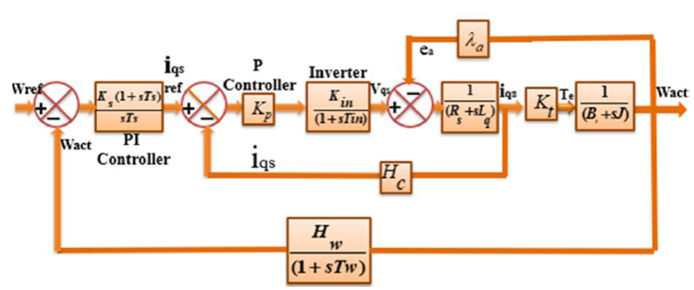
Figure 2 points the two-loop control configuration of the projected simplified closed loop BLDC drive with the relevant transfer functions of each block (Das & Biswas, 2020b; Krishnan, 2001). The output from the current controller is supplied to the inverter for the production of the triggering pulses at some particular sequence. In this proposed method, the output from the speed controller has been assumed as the quadrature axis component iqs, is solely liable for the development of electromagnetic torque. To validate the mathematical convention, we are considering direct-axis voltage Vds = 0 as the estimated dynamics of the BLDC suits. This reference current has been measured to compare with the ideal quadrature stator current (iqs), and the error in the current signal is supplied to the proposed current controller. The current control loop has been incorporated for controlling the quick response of current with minimum overshoot (Krishnan, 2001).
3. Detailed closed-loop BLDC motor drive
To establish a standard closed-loop framework consisting of both current and speed control loop, controller selection plays an essential role in specific applications for much better performance. Nevertheless, the current loop will run quicker than the outward speed loop so that the PI system is best suited as a current controller. By using a speed sensor, a self-functioned closed-loop BLDC motor drive is gained where knowledge of the set speed value and the optimal speed is continuously obtainable. This speed controller operates on an electronic front-end power converter with a regulated dc voltage (Vdc) output. A PWM has named topology for the self-synchronous source voltage inverter that provides the BLDC motor with switching pulses (Das & Biswas, 2020c; Gujjar & Kumar, 2017).
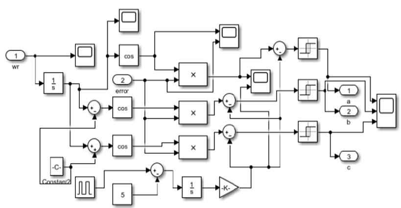
A sinusoidal pulse width modulation (SPWM)-based overall closed-loop assembly of a self-functioned complicated adjustable speed BLDC motor drive with a self-synchronous VSI supplying unit is considered. The inverter switches are controlled synchronously with the estimation of rotor location and the control approach is achieved by the technique of SPWM. The detailed structure of this system is depicted in Figure 3. The various sub-systems such as inverter architecture, production of SPWM signals utilising switching logic and full BLDC drive like torque-speed computing strategy were subsequently modelled and tested in this proposed model of BLDC motor drive. PI controller is utilised in the current loop and the PID controller is used in the speed loop. A theoretical model of a BLDC motor drive is depicted in this segment for the creation of the two-loop control arrangement. The PI controller's gain is tuned concerning the new model's parameters. The control signal of the PI controller and the real rotor speed are given as input to the SPWM inverter in this comprehensive model. This overall architecture for the proposed model consists of different sub-systems and these subsystems are the representation of the analytical model of the BLDC motor drive. The calculation of the permanent magnet rotor location is done by integrating the machine's electrical rotor speed. The control loop controller PI output is functions as quadrature axis voltage though the input was quadrature-axis current. The primary consideration for the closed-loop model null value of the d-axis voltage with some condition mentioned in the earlier section of the mathematical modelling of the closed-loop BLDC drive. The output of the current controller, along with the rotor speed, is taken as input for the SPWM subsystem. Inside the block from the angular velocity, the rotor position is derived by using an integrator. The cosine of the rotor position and the current controller output is merged and logically compared with a triangular wave generated by integrating the square wave pulse. And thus, the three sinusoidal voltages are generated. In MATLAB simulation, as shown in Figure 8, the summer and relay block together realize the comparison logic among all of the three sin and the triangular wave. Ultimately, the sine wave outputs are passed through the three relay blocks, and three necessary binary signals sa, sb, and sc are generated that determines the switching of the 2-level SPWM VSI. The sub-system of voltage source inverter is demonstrated in Figure 9, where those binary signals are given as input. Mainly, these signals were produced by the PWM control strategies of swapping combinations of Equations 1,2,3 and produce the three-phase stator voltages.


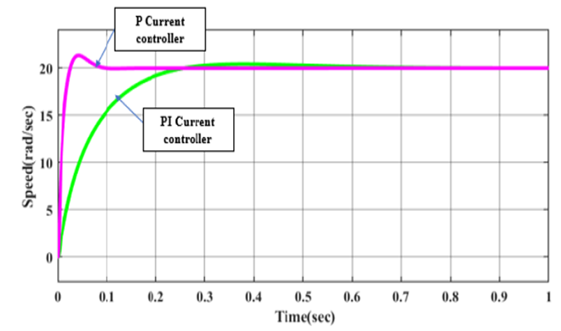
Figure 5 Comparative analysis of step responses with the PID speed controller and the current loop using the P and PI controller of the simplified closed-loop BLDC motor.
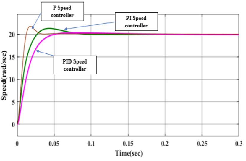
Figure 6 Comparative step response’s characteristics of the simplified closed-loop BLDC motor with the PI current controller and the speed loop using the P, PI and PID controller.
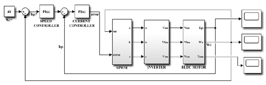
Figure 7 Overall analytical closed-loop model of the speed-controlled BLDC drive with classical controllers.

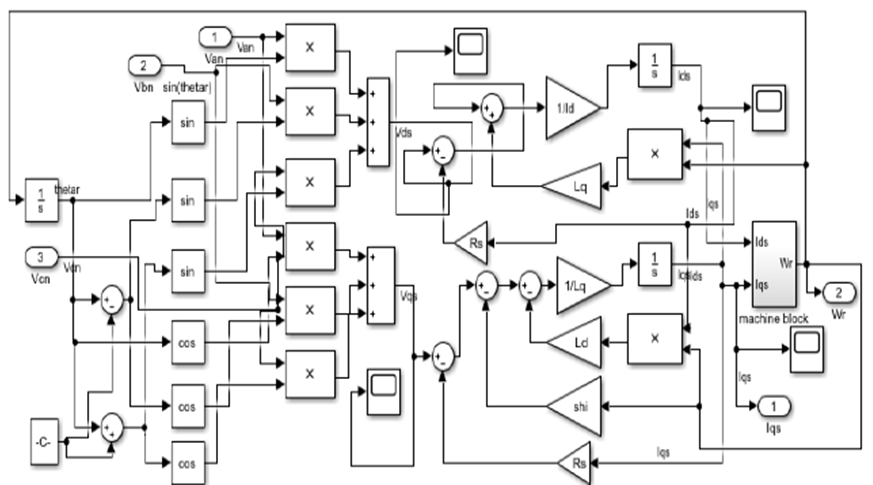
The BLDC motor armature is supplied with these output voltages of the sinusoidal PWM powered voltage source inverter. The voltages of the step that come from the inverter device moved on to the BLDC motor sub-system unit, as depicted in Figure10, to measure the motor dynamics. In this sub-system, another subsystem is accommodated, called torque-speed computing block. This inner subsystem measures both the torque and speed from the currents of the q-axis and the d-axis. The voltages generated in the armature of a BLDC machine, presuming the motor to be stable is illustrated by the subsequent equations (Das & Biswas, 2020c).
Where Vdc represents the dc-link input voltage of the vsi and sa, sb & sc represents the changeover combinations of the vsi under various switching instants. The electromagnetic torque Te is calculated from the flux linkages associated with direct and quadrature axis and the direct and quadrature axis currents given by Equation4 (Das & Biswas, 2020c).
The complex and steady amplitude of the electromagnetic torque Te should be controlled through the combined operation of the moment of inertia of the due to the momentum of the motor and the associated load torque. Taking into account the technical parameters of the unit, such as the moment of inertia, the coefficient of damping the speed is represented by Equation5. It is assumed that the load torque on the machine consists of two elements, the first one does not depend on speed and the second one depends on the rotor's mechanical speed. So, the electromagnetic torque in terms of load torque is expressed by Equation 6. And the generalized transfer function of the current controller, PI and speed controller, PID is presented by Equations7 and 8.
Where the proportional, integral, and derivative gain are represented by Kp, Ki, and Kd, correspondingly. These gain values are calculated from the system's overall control mechanism and also tuned in MATLAB as per the stability requirement of the drive. An analysis is presumed for the specific motor parameters. By varying the speed and current controller by using the different combinations of the classical controller along with the variation of their gains, the output of the overall closed-loop drive system can be varied. The right controller selection and exact parameter tuning can enhance the drive's stability
4. Simulations and results
4.1. Simplified closed-loop model with classical controllers
A standard performance analysis is implemented to familiarize with the closed-loop system's different time-based performance parameters. The time-domain parameters of the closed-loop system such as peak time, settling period, steady-state error, etc., are simulated, which in turn helps to familiarize with the output of the final controlled BLDC drive. These various performance indices can be taken for evaluating both the dynamic and steady-state outcomes of the closed-loop BLDC drive. As the overall structure consists of two loops; thus, separate controller combinations are chosen for the analysis of the closed-loop model. The simulation diagram of PID as speed and PI as the current controller combination is illustrated by Figure 4.
The performance of a control system depends heavily on the parameters of its time domain. A control system's time response is typically split into two sections: the transient response and the steady-state response. The transient characteristics frequently display damped oscillations before it enters a stable state. Six types of Different variations of classical controllers are listed for deciding time-domain performance characteristics. Combinations are chosen for analyzing system behavior. The corresponding time-domain factors of these combinations are tabulated in the Table 1.
Table 1 Comparison of step response of different combinations of classical controllers.
| Speed Controller | Current Controller | Rise Time (Sec) | Peak Time (Sec) | % Overshoot | Settling Time (Sec) |
| 15.159 | 4.478 | 0.00536 | 0.0125 | 19.5 | 0.0298 |
| 69.84 | 0.00816 | 0.0177 | 9.39 | 0.0292 | |
|
|
|
0.0267 | 0.0786 | 1.82 | 0.0428 |
|
|
4.478 | 0.147 | 0.379 | 2.14 | 0.425 |
|
|
|
0.0171 | 0.0436 | 6.71 | 0.074 |
It is observed that rise time is much less in the 1st combination, where both the controllers are P-type. But in such an arrangement, the peak overshoot is highest compared with other combinations along with the presence of significant steady-state error, as shown in Table 1. The settling time is correlated with the system's highest time constant. Since the settling period is inversely proportional to the system's undamped natural frequency, the damping ratio value is usually determined by the highest allowable overshoot limit. It is found that in the 2nd combination of P and PI as speed and current controller, respectively, the model is settled faster among the six instances. If the response's final steady-state value varies from unity, then the percentage overshoot is widely utilized. The overall overshoot number reveals the relative stability of the system directly. The application of PI control operation in both loops is observed to decrease the percentage overshoot and thus increase system performance. The implementation of proportional control in both the loops escalates the steady-state error of the system, but still, the introduction of PI as the current controller decreases this error. Except for these two combinations, other types can nullify the steady-state error. Through implementing a PID speed controller and PI current controller doesn't show any improvement of the system compared with PI as both the controller. The time response analysis values tabulated in Table 1 confirms the above illustration. A comparative plot of different current controllers for the PID speed controller is demonstrated with Figure 5 to clarify the difference of current controller responses with different classical controllers. The plot signifies the vitality of PI to minimize the overshoot of the system and the P controller to enhance the time factors related to the closed-loop system. Another comparative plot of Figure 6 shows the versatility in responses of the speed controller as P, PI, and PID to the PI current controller. The idea can be established from these comparative analyses that the addition of each of the gain factors with the P controller decreases the overshoot of the system, which is best at the time of PID, but it also makes the system slow.
4.2. Detailed closed-loop model with the classical controllers
An overall analytical closed-loop MATLAB simulation model of the BLDC drive is presented in Figure 7, consisting of sinusoidal pulse width modulation (SPWM) switching, voltage source inverter and then the machine block with torque-speed calculating mechanical block (Das & Biswas, 2020c).
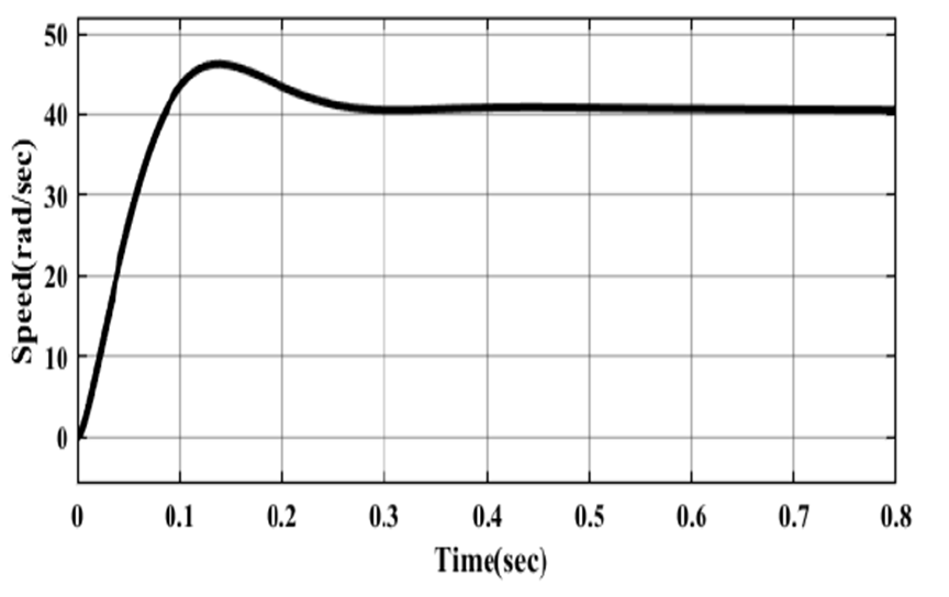
Figure 8 shows the subsystem of the SPWM switching block, and the subsystem of the two-level voltage source inverter is presented in Figure 9. The BLDC motor subsystem is shown in Figure 10, and the machine block subsystem to calculate the motor core parameters, i.e., speed and torque inside the motor block, is presented in Figure 11. A reference speed of 40rad/sec is considered as input. The output responses are observed from the respective scopes of MATLAB simulations. And as mentioned earlier, these Simulink designs are done based on the mathematical modelling on the closed-loop BLDC motor drive considering the classical controllers as speed and the current controller, The Simulink model considers here is comprise of the PID speed controller and the PI current controller. The performance analysis of the closed-loop model is done by plotting various parameters of the BLDC motor. The electromagnetic torque of Figure 12 has been improved as now, and the torque ripples are diminished due to the application of SPWM compared to the open-loop system. The speed waveforms in Figure 13, as predicted by this model are having very small ripples because of the SPWM operated VSI and also shown some steady-state error as compared with the ref input of 40rad/sec the output is higher which also shows some overshoot in the speed response.
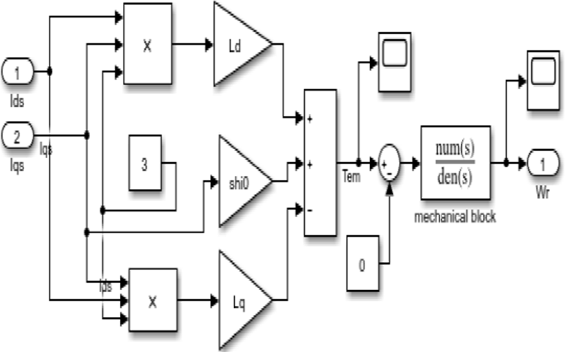

Figure 12 Torque responses vs. time for the detailed closed-loop model utilizing the classical controllers.
4.3. Simulation of the simplified closed-loop model with the fuzzy logic controller
The Figure 14 is showing the simplified simulation model with fuzzy logic controller and the rule base of the fuzzy logic controller for this simplified model is given in Table 2. Two membership functions, such as speed and change in speed,are taken as input, and the quadrature axis current is the output membership function. It can be seen from the comparative analysis of Figure 15 that applying the fuzzy logic with the PI controller, the system’s overshoot is minimized but the rise time has increased compared to classical control topologies. The fuzzy logic controller attains a steady-state, and this attained speed is almost equal to the reference speed, which means less steady-state error. This is because the fuzzy logic controller is centered on the random acquaintance of data. The motor delivers the required output subsequently as the controller foremost has to acquire from or fine-tune conferring to the data afforded by the manipulator. After implementing the fuzzy logic controller in place of the classical controller, we got a better step response in terms of overshoot. Still, the time base parameters are having higher values compare to the classical controllers.
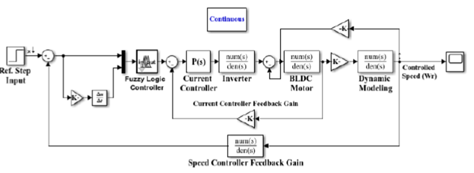
Figure 14 SIMULINK block diagram of a closed-loop BLDC motor drive employing the classical controllers and the fuzzy logic controller.

Figure 15 Comparative analysis of step responses with the fuzzy and classical controller of the simplified closed-loop BLDC motor drive.
4.4. Simulation of the detailed closed-loop model with the fuzzy logic controller
The proposed model built in this article is a closed-loop BLDC drive with a VSI driven by a self-synchronous PWM where the armature voltage d-axis variable, Vds, is held to nil. The output of the controller begins with a speed comparison where the system is supposed to operate within a reasonable range irrespective of the adjustments in the load. To order to ensure the almost zero steady-state speed loss, the information for this recommended speed is given to a fuzzy speed controller. The suggested fuzzy speed controller's simple goal is to balance the reference speed with the real BLDC motor reference speed for such a nonlinear dynamic response. The speed sensor performance measures the torque, or analog current signal is transmitted to an existing device as a PI controller. Subsequently, all the required sub-systems within the MATLAB/SIMULINK framework are modelled using mathematical modelling, and the respective tests are performed. The comprehensive model is simulated in the MATLAB/SIMULINK and is shown in Figure 16.
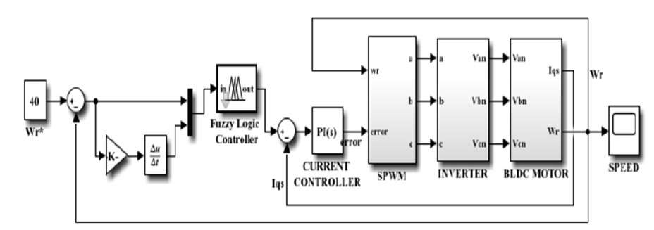
Figure 16 Overall mathematical model-based closed-loop speed controlled BLDC drive with the fuzzy logic controller.
Subsequently integrating all the essential fuzzy rules of Table 3 and with an applied reference speed of 40rad/sec and all the operational circumstances retaining the identical in this projected model. Two inputs are again considered to accomplish the fuzzy-based speed controller for the closed-loop model of the overall data. Here, for two inputs and one output, the same seven-member feature was considered. The two-inputs are difference in the set value of speed as error and change in speed error, and the output is the actual quadrature axis current.
Table 3 Fuzzy rule base for Overall mathematical model of BLDC motor drive.
| e | Δe | PL | PM | PS | Z | NS | NM | NL |
| NL | Z | NS | NM | NL | NL | N | NL | |
| NM | PS | Z | NS | NM | NL | NL | NL | |
| NS | PM | PS | Z | NS | NM | NL | NL | |
| Z | PL | PM | PS | Z | NS | NM | NL | |
| PS | PL | PL | PM | PS | Z | NS | NM | |
| PM | PL | PL | PL | PM | PS | Z | NS | |
| PL | PL | PL | PL | PL | PM | PS | Z | |
The comparative speed response in Figure 17 after applying 40 rad/s reference speed, it may be concluded that a fuzzy speed controller minimizes steady-state speed error significantly in this proposed approach, which also shows improved overshoot of the closed-loop system. Moreover, from the speed response, it claims that speed stables within a shorter period, which is appreciable. Furthermore, the design of a fuzzy logic-controlled speed controller minimizes the steady-state error of the system prominently for such reliable operation. The comparative analysis of electromagnetic torque in Figure 18 shows that the magnitude is initially high but slowly fixes to the stable value for standardized electromagnetic torque production. Eventually, a lower torque ripple, which is an essential dynamic output predictor, is developed with the introduction of the fuzzy controlled strategy. These plots clearly show that the ripples in the responses have been decreased with the execution of a fuzzy controller in the system. Thus, the fuzzy logic controller improvises the system performance in comparison with the classical controllers.

Figure 17 Comparative analysis of speed response of the overall mathematical model-based closed-loop BLDC motor with the fuzzy and the classical controller.

4.5. Simulation of the simplified closed-loop model with the PSO optimized controller
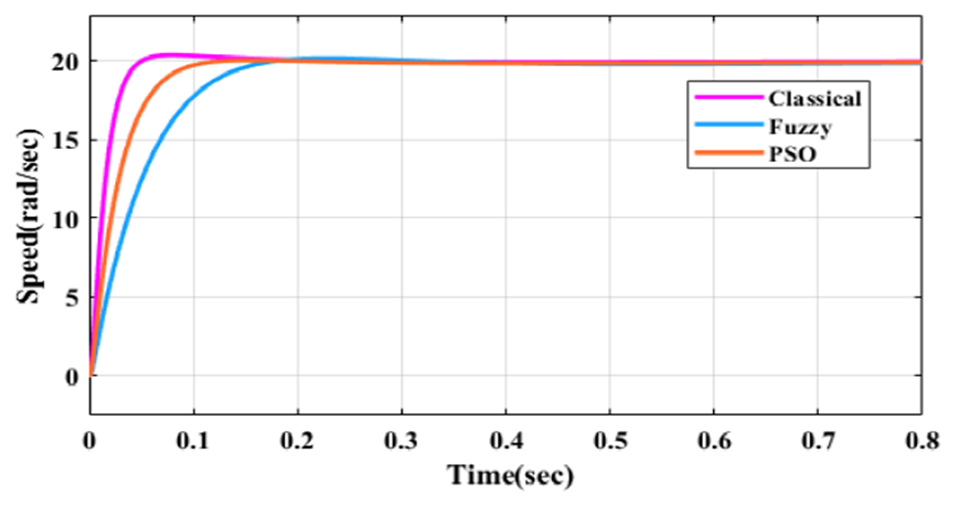
It can be noted from the above figures and the former section that while using the fuzzy logic controller, the overshoots attained are lesser as compared to the case when the classical controller is used, but the rise time is more substantial. The fuzzy logic controller compared with the classical controller; however, gives a better response according to the applied reference speed. It tends to approach the reference speed by taking more time but has, comparatively, a very low overshoot. The fuzzy logic controller attains a steady-state speed response which is almost equal to the reference speed. This is because the fuzzy logic controller depends on random knowledge of data (Das et al., 2018). But this data is not an optimized output of the system. After implying the PSO in the system, the machine provides a desirable response in lesser time compared to the fuzzy control and adjusts according to the data provided by the user. The overshoot is also lesser than the fuzzy control and zero steady-state error. Figure 19 presents the comparative step base output characteristics of the simplified closed-loop BLDC system with the fuzzy, classical controller and PSO which predicts that after implementing particle swarm optimization to find the optimized gains of the classical controller we got better step response in terms of overshoot and also the time base parameters have lesser values compare to the fuzzy controller.
4.6. Simulation of the detailed closed-loop model with the PSO optimized classical controller
It can be observed from the speed response the overshoot, and the steady-state error in the speed response vanishes as it was happening with the standard classical controller. Another observation that can be made is that the system becomes slightly sluggish, i.e., it is used to attain its desired speed in slightly higher time than a typical classical controller, but it is faster than a fuzzy controller. After implying the fuzzy controller still, there was some overshoot present in the system. After optimizing the system with PSO, nearly zero overshoot is attained with its required speed of operation. All the observations, as mentioned earlier, are made from Figure 20, which depicts the speed response of the closed-loop model with the calculation of controller variables by the method of particle swarm optimization. From Figure 21, it is found that the ripples in the electromagnetic torque are reduced. The ripples present at the beginning of the graph, which can be found in the case of both the classical and fuzzy controllers, almost vanish, and the smooth plot appears. Some negligible ripples are present at the end of the electromagnetic torque plot. All these plots show the excellent optimizing property of PSO.


4.7. Simulation of the simplified closed-loop model with the GA optimized classical controller
The genetic algorithm displays its proficiency in the existence of considerable nonlinearities to accomplish the best regulation of electric drive speed regulators. Genetic algorithms can be expended in surroundings where there is insufficient system consciousness or excessive exertion. For parameters such as crossover and mutation, these algorithms may trace optimal outcome in the search domain. Genetic algorithms are vital tools to locate a sensible solution to a difficult problem fast (Das & Biswas, 2020a; Ridwan et al., 2017). They're not fast, but they can do a decent quest.
Table 4 shows the comparative analysis of the step response of the system with the fuzzy controller and the optimization technique. The best time-domain response of the system is achieved with a genetic algorithm enhanced PI speed and the simple PI current controller. These data, clearly describes that the GA boosted PI speed controller with PI as the current controller delivers a better personalized controlled output than any other optimization technique. The comparative analysis plot of classical, fuzzy, PSO, and GA in Figure 22 clearly shows that the best optimized output is achieved by implementing the genetic algorithm on this simplified closed-loop control of the BLDC motor drive. Here, the optimized output has zero overshoot and steady-state error, and also, the time response analysis has shown a tremendous improvement. The solutions after implementing the genetic algorithm-optimized PI speed controller removes the over-shooting of the system and also establishes further substantial perfection of the transient behavior with a step input.
Table 4 Comparative study of Performance of the system with fuzzy controller and optimization technique.
| Speed controller | Current controller | Rise time | Peak time | Peak overshoot | Settling time | Final value |
| PI | PI | 0.0267 | 0.0786 | 1.82 | 0.0428 | 20 |
| Fuzzy | PI | 0.0967 | 0.228 | 0.84 | 0.149 | 20 |
| PSO based PI | PI | 0.0555 | 0.15 | 0.225 | 0.0932 | 20 |
| GA based PI | PI | 0.0138 | 0.03 | 0 | 0.0223 | 20 |

4.8. Simulation of the detailed closed-loop model with the genetic algorithm-optimized classical controller
The GA optimized PI values are used in the overall proposed model. It is observed in the speed plot shown in Figure 23 that the steady-state error and maximum peak overshoot, which was happening with the standard tuned classical controller and some extent with a fuzzy controller of the speed response, is removed the same like the response of PSO. But in the case of a fuzzy controller or even in that of the PSO, the system becomes sluggish, i.e; it is used to attain its desired speed in slightly higher time than the GA-based controller. After optimizing the system with GA, nearly zero overshoot is attained with its required speed of operation in very less time, which shows its high transient-based stability. The comparative analysis of Figure 26 of the detailed closed-loop motor drive shows the variation of speed responses. with the classical, fuzzy controller, PSO, and the GA-based speed controllers.

Figure 23 Speed response vs. time for the detailed closed-loop model utilizing the genetic algorithm.

Figure 24 Electromagnetic torque vs. time for the detailed closed-loop model utilizing the genetic algorithm.

Figure 25 Comparative analysis of speed response vs. time of the detailed closed-loop BLDC system with the PSO and GA-based speed controller.
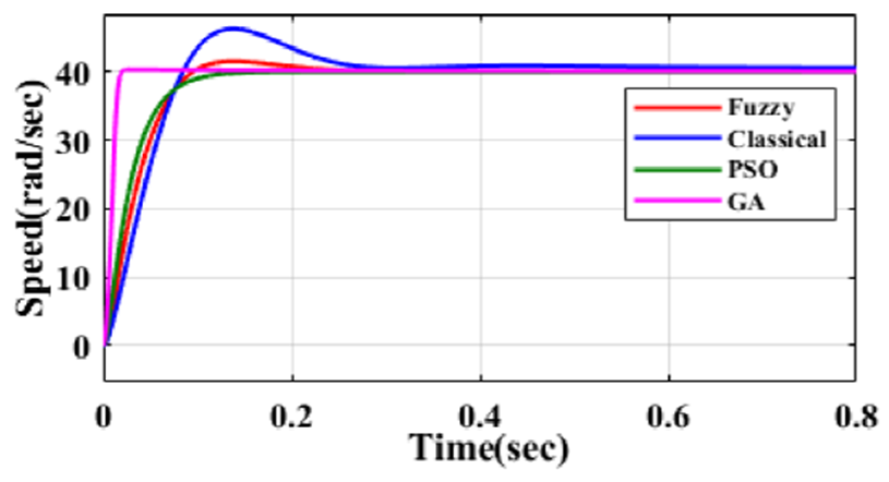
Figure 26 Comparative time response characteristics of the simplified closed-loop BLDC motor with the fuzzy, classical controller, and the PSO and GA-based speed controller.
From Figure 25, the clear idea of the effect of GA can be understood. It is also observed that the ripples in the electromagnetic torque are almost nullified compared to any other controller or even with the PSO technique illustrated in Figure 24. PSO almost vanished the ripples present at the beginning of the graph, which can be found in the case of both the classical and fuzzy controllers, but GA provides a better-smoothed response of the electromagnetic torque. Usually, GA gives the platform to the user to select the optimized value, and so the optimized output can be chosen from the MATLAB toolbox window (Das & Biswas, 2020a; 2020b), and thus these plots show the excellent optimizing response of GA than any other applied control optimization technique.
5. Conclusion
This paper notably establishes the comparative performance optimization towards a simplified closed-loop BLDC drive using different classical controllers. A simplified method has been incorporated to analyze and associate the various performance constraints of a complete control assembly. An exhaustive, as well as comparative analysis, is introduced to familiarize with the system’s dynamics. The typical dynamic behavior of the proposed BLDC drive has been examined and observed. Therefore, the dynamic and steady-state behavior of the system improves drastically with the PI and PI combination of the current and speed controllers by which the expected speed is achieved more smoothly. More sophisticated control is obtained by tuning the controller’s gains for dynamic performance enhancement. A self-functioned detailed closed-loop BLDC drive is attained by employing a speed controller, whose input depends on the difference of the required speed and the measured speed. The controlled signal acts on a converter which produces a controlled dc voltage (Vdc) signal via a current controller to protect the converter from the sudden rise of current in the system. A PWM assigned topology of the self-synchronous voltage source inverter giving supply to the BLDC. While implementing the PWM operated control strategy, reduced toque ripple in a BLDC machine can be achieved compared to open-loop control (Das & Biswas, 2019; Das et al., 2018; Das et al., 2019). The fuzzy controller plots clearly show that the ripples in the responses has been decreased in the torque along with providing a better speed response with lesser overshoot and error and also improved time response. But the system shows better improvisation when goes through the PSO and GA optimization technique in comparison with both the classical and fuzzy controllers. Among these two-optimization techniques proposed, the GA shows the best response of the system by minimizing the torque ripple and time and overshoot factors of the closed-loop BLDC motor drive.

