


 text new page (beta)
 English (pdf)
 Article in xml format
 Article references
 Send this article by e-mail
 Cited by SciELO
  Similars in
SciELO
Similars in
SciELO 
 Permalink
1. Introduction
Nowadays, magnesium (Mg) alloys and their composites have received significant attention in the aerospace and automotive industries due to their unique properties, such as high particular strength and stiffness to density ratio. This has made Mg an ideal element to be used in places where weight reduction is imperative (Gupta & Ling, 2011). However, the instinctive properties of Mg, such as low elastic module and wear resistance lead to the restriction of Mg alloys usage in some applications when appropriate mechanical and tribological properties are needed. To overcome the drawback, numerous studies have been carried out to enhance the mechanical and wear properties of Mg alloys (Mehta et al., 2004; Mordike & Ebert, 2001). Among the diverse methods to improve certain restrictions of Mg, such as powder metallurgy and spray deposition, synthesis of Mg-based metal matrix composites with reinforcement particles using stir casting technique is a simple and cost-effective method (Sun et al., 2017). In addition, among the ceramic reinforcements to fabricate metal matrix composites (MMCs), SiC and CNTs are more renowned due to their high hardness values, high elastic modulus, and low price, also, they do not react with Mg matrix ( Li et al., 2017; Lim & Gupta, 2003;). Many investigations have been accomplished on the influence of SiC particles’ integration with Mg alloys. It is known that SiC particles are capable of effectively reducing the grain size of magnesium aluminum (Mg-Al) alloys by acting as grain refiners (Schiffl & Easton, 2009). (Deng et al., 2010) stated that reinforcing AZ91 Mg alloy with 1.5 vol.% sub-micron SiCp resulted in grain size reduction with improvement in the mechanical properties (YS (yield strength) and UTS) of the composites. (Shen et al., 2014) demonstrated that AZ31B reinforced with SiC culminated in more completed dynamic recrystallization (DRX) during hot extrusion, elastic modulus, and higher strength. In addition to the beneficial features of SiCp in producing MMCs, recently, CNTs have also attracted significant attention due to their spectacular thermal, electrical and mechanical properties, such as high strength (30GPa) and stiffness (1TPa) (Yu et al., 2000; Zhou, Bai et al., 2009). Multiple experimental studies have been employed to demonstrate the influence of CNTs on the microstructural and mechanical behavior of aluminum (Al) alloys (Bakshi et al., 2010) and less attention was given to Mg alloys. (Han et al., 2015) reported that by adding 0.05vol.% CNTs to AZ31 alloy, not only the tensile yield strength of AZ31 improved, the compressive yield strength was also 53% greater than monolithic AZ31. The reason for such enhancement was inextricably attributed to the role of CNTs in decreasing the grain size by nucleating heterogeneously, and good interfacial bonding with the matrix (Han et al., 2015; Uozumi et al., 2008). Shi-Ying et al. (Liu et al., 2010) declared that 1.5%CNTs/AZ91D showed 22%, 21% and 42% improvement in tensile strength, yield strength and elongation of the nanocomposite, respectively. Furthermore, reinforcement particles like SiC and CNT particles can alter the wear behavior of materials. (Lim et al., 2003) demonstrated that the wear behavior of SiC particles reinforced Mg-MMCs by conducting pin-on-disk configuration under different loads was better than monolithic alloy. Moreover, Umeda et al. (2009) depicted that wear resistance and coefficient of friction of the hybrid composites improved and lowered respectively by using CNTs and silica (SiO2) reinforcement. Among the Mg alloys, Mg-Zn-Cu series alloys, such as ZC71 alloy has been introduced as a member of new family of magnesium alloys which owns high mechanical properties (UTS=215-260 MPa, El.%=3-8) and corrosion resistance as well as heat treatment capability (Polmear, 1994). MgZnCu and Mg(Zn,Cu)2 eutectic phases are two distinctive intermetallics that are formed in the low zinc (Zn)-content and high Zn-content of the Mg-Zn-Cu alloys, respectively (Golmakaniyoon & Mahmudi, 2011). To the best of the authors’ knowledge, limitation exists on the combined influence of SiC and CNT on the microstructure, mechanical and tribological properties of Mg-Zn-Cu system alloys. Hence, the purpose of the present study was to investigate the influence of MWCNT addition as well as SiC particles with various contents/sizes on the microstructural alteration, mechanical properties and wear behavior of the ZC71 Mg alloy.
2. Experimental procedure
The starting materials to prepare the MMCs were ZC71 (6-7 wt. % Zn and 1-1.5 wt. % Cu) Mg alloy as the matrix, and SiCp (with an average diameter of ~ 25 µm) and MWCNTs (10−20 nm in diameter and 10−30 µm in length) as the reinforcements. The silicon carbide particles (SiCp) used in the paper has hexagonal lattice structure (β-SiC). The SiC poses high hardness and temperature stability up to 1400 °C. Also, the density of SiC is 3.2 g/cm3 (Harris, 1995). The multi wall carbon nanotubes that used in the paper are commercial and they were provided by Neutrino trading company. To be more elucidated, MWCNTS are made by CCVD and purified using concentrated acid chemistry (Dupuis, 2005). The chemical composition of the ZC71 alloy is tabulated in Table 1. In order to fabricate the MMCs, the ZC71 Mg alloy was melted inside the graphite crucible using induction furnace under inert atmosphere gas that comprised of a mixture of carbon dioxide (CO2) and sulfur hexafluoride (SF6). Thereafter, 5.0 wt. % of SiCp was added into the melt via stir casting process at 1033 K (760 °C) with a constant rotational speed of 750 rpm and stirring time of 20 min. Finally, after skimming the slog, the melt was carefully casted inside a preheated cylindrical mold with a diameter of 30 mm and height of 50 mm. The procedure was repeated for 10 wt. % SiCp. In another experiment, MWCNTs were added to ZC71-5wt. %SiCp (25 µm) composite using stir casting, and a preliminary processing method was utilized to unbundle the MWCNTs. To achieve this purpose, block copolymer Disperbyk-2150 was used as a dispersing agent to facilitate the dispersion of MWCNTs in ethanol (Bright et al., 2006; Li et al., 2004). Firstly, the block copolymer was dissolved in ethanol inside a beaker. After ultrasonic treatment for 5 min, the MWCNTs (0.5 wt. % of ZC71-5wt. %SiC composite, math ratio to the block copolymer 1:1) were added to the solution. After 15 min of ultrasonic treatment, the mixture was subsequently stirred for 25 min at 250 rpm. Then, Mg chips were added to the suspension and the mixture was further stirred until the ethanol evaporated. In order to synthesize the hybrid ZC71/5wt. % SiC- 0.5wt. % MWCNT MMC, ZC71-5wt. %SiC was melted and 0.5wt. % MWCNT (in the form of Mg-MWCNT chips) was added into the melt using the aforementioned casting procedure. The variation of SiC particle size (5 µm and 15 µm) is another parameter to be investigated in this experiment. In this context, the hybrid ZC71/5wt. % SiC- 0.5wt. % MWCNT MMCs were produced using SiC particle sizes of 5 µm and 15 µm, similar to the fabricated hybrid MMC with SiC particle size of 25 µm. Tensile and Vickers hardness tests were carried out to characterize the mechanical properties of the ZC71 alloy and fabricated MMCs. The Vickers hardness measurements were accomplished with a load of 100 Kgf (980.665 N) and holding time of 20 s. ASTM E8-04 standard used to fabricate the tensile test specimens and for each composite the tensile tests were conducted according to ASTM: E8 / E8M - 16a using a digital testing machine (Instron) at a constant cross-head speed of 1 mm/min. For each condition, four samples were tested to observe repeatability. To investigate the wear behavior of the ZC71 alloy and MMCs, the sliding wear test was conducted based on ASTM: G99 - 05(2010) standard with an applied load of 20N, sliding velocity of 200 rpm and sliding distance of 2000 m using the pin-on-disc configuration (Ducom, TR20-LE) with steel disc (hardness 60 HRC) as the counterpart. For each condition, a set of three specimens was tested. For microstructural observations, the ZC71 alloy and fabricated MMCs were cut and underwent the metallography procedure (including grinding with SiC papers and polishing with colloidal silica suspension) and finally etched in acetic picral solution (5 ml acetic acid + 6 g picric acid + 10 ml H2O + 100 ml ethanol) (Golmakaniyoon & Mahmudi, 2011). The etched samples were observed using an optical microscope equipped with an image analyzer (ImageJ) for the analysis of Mg grain size. Linear intercept method was used to measure the average grain size of the as-cast and as-extruded specimens according to ASTM E112-13. In order to measure the average grain size, linear intercept method was used based on the ASTM: E112-13 standard. The SEM (Vega©Tescan) equipped with EDS facility was utilized to observe the microstructure of the samples, tensile fracture and worn surfaces of the specimens. For phase identification, binary diffractometer with Cu-kα radiation was utilized.
3. Results and discussion
3.1. Characterization of the microstructure
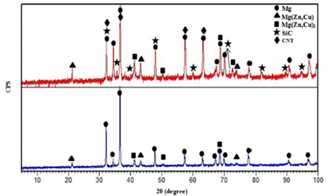
Fig. 1(a) interprets the SEM micrograph of the ZC71 alloy structure. The alloy had a dendritic structure and obviously the primary α-Mg (marked with A in Fig. 1(b)) was surrounded by a semi-continuous network of bright intermetallic compounds (IMCs) that were distributed in dendrite arms/boundaries. As observed in the higher magnified SEM micrograph (Fig. 1(b)), the IMCs appearred in two different morphologies, i.e., small massive particles located between the dendrite arms (B), and lamellar structure located at the dendrite boundaries (C). In order to determine the composition of the IMCs, XRD and EDS analyses were conducted. Based on the EDX (Fig. 1(c)) and XRD results (Fig. 2), the lamellar structure was indicated as Mg (Zn,Cu)2, while the tiny bulky particles were denoted as MgZnCu. The results were consistent with the findings of a previous study on the shape and composition of the IMCs (Golmakaniyoon & Mahmudi, 2011).
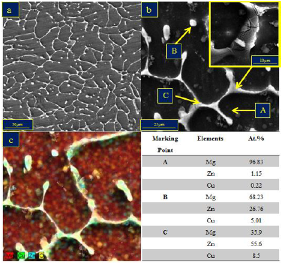
Figure 1.(a) BSE micrograph of ZC71 alloy, (b) higher magnification of ZC71 alloy illustrating Mg matrix (A) and the semi-continuous network of bright intermetallic compounds (IMCs); (B) small massive particles and (C) lamellar structure, (c) elemental mapping and corresponding EDX results of IMCs in (b).
The influence of different SiC increment on the structure of the ZC71 alloy is demonstrated in Fig. 3. As shown in Fig. 3(a) −Fig. 3(f), with the addition of 5 and 10 wt. % SiC particles, the grain size and the volume fraction of the MgZnCu and Mg (Zn.Cu)2 IMCs were obviously decreased. It can be seen that the dendritic boundaries are involved by most of the SiC particles. This is because the solid/liquid face forced the SiC particles which lead to their segregation in the interdendritic regions. By increasing SiC addition to 10 wt. %, SiC agglomeration occurred, which can be observed in Fig. 3(e) and Fig. 3(f). In general, the increasing content of reinforcement particle causes the occurrence of agglomeration in the composite, which can be associated with the reinforcements with finer size and differences in parameters, namely, the stirring speed, temperature and time (Gui et al., 2004). Furthermore, with increasing the reinforcement volume percentage, the composite porosity is increased (Fig. 3). The uniform distribution of the silicon carbide particles magnesium alloy melt in the can be achieved by proper controlling of the stirring movement. Thereafter, the viscosity and fluidity of the melt increase and decrease respectively. With increase in the content of the reinforcement, the porosity increased which is due to the entrapment of gas bubbles during solidification (Gui et al., 2004).
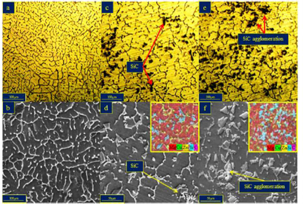
Figure 3 Optical and SEM micrographs of the cast ZC71 (a, b) and ZC71 composites reinforced with 5 wt. % SiCp (c, d) and 10 wt. % SiCp (e, f).
The variation of grain size and the macrostructure of the ZC71 alloy and composites containing 5 and 10 wt. % SiC particles is displayed in Fig.4. Based on Fig. 3 and Fig. 4, it can be seen that the incorporation of SiC particles to the ZC71 alloy results in the formation of nearly equiaxed grains. The average grain size of the ZC71 alloy decreased from 325.5 µm to 123.9 µm and 33.7 µm with the addition of 5 and 10 wt. % SiC, respectively. The reduction in grain size of the ZC71 alloy as a result of the SiC addition can be associated to the role of SiC particles to restrict the grain growth. Furthermore, the SiC particles acted as the heterogeneous nucleation sites for primary α-Mg phase during the solidification process. The addition of more SiC particles (10 wt.%) (Fig. 3(e) and Fig. 3(f)) led to greater reduction in grain size and dendritic regions, thus causing the SiCp to agglomerate. Therefore, it was concluded that 5wt.%SiCp was the best value to achieve adequate grain refinement with uniform distribution of SiCp.
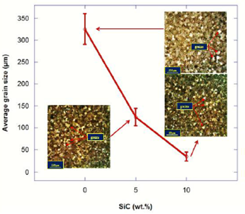
Figure 4 Grain size as well as macrostructure of ZC71 alloy and composite containing 5 and 10 wt. % SiC particles. ZC71 composites
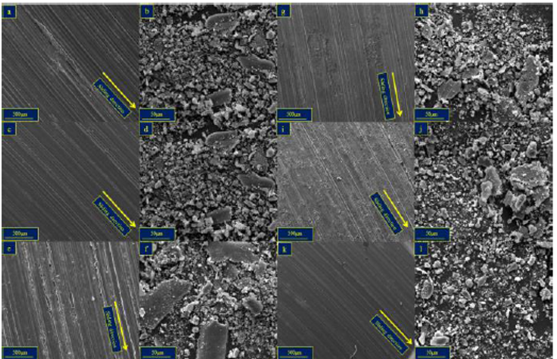
The optical and SEM micrographs, and macrostructure of ZC71-5% SiC and ZC71-5% SiC-0.5 MWCNT hybrid composites with varying SiC sizes are shown in Fig. 5(a) −Fig. 5(l). The figures indicate a relatively proper dispersion of SiC and MWCNT in the matrix. Fig. 5 depicts the influence of MWCNTs addition on the average grain size of the ZC71 alloy. The grain structure of the ZC71- 5% SiC composite (SiC size = 25 µm) (Fig. 5(c)) was significantly refined when MWCNTs were added to the composite (Fig. 5(f)). The grain size of ZC71-5%SiC decreased from 123 µm to 112 µm in the ZC71-5% SiC-0.5 MWCNT hybrid composite under the two-step preparation method of MWCNTs comprising unbundling the MWCNTs via ultrasonic treatment and subsequent integration of MWCNTs with Mg chips through mechanical stirring. The introduction of CNTs into the composite led to the provision of some heterogeneous nucleation substrates during solidification. This resulted in the reduction of grain size of the matrix alloy in the ZC71/ (MWCNT + SiC) composite to some extent. On the other hand, the distribution of MWCNTs and SiC particles was enhanced in the ZC71-based hybrid composite. To obtain good mechanical properties, these can be considered as the main requirements. The results were consistent with the findings reported by Zhou et al. (2012) where, in the AZ91/(0.7% MWCNT + 0.3% SiC) composites, micrometer-sized SiC particles and MWCNTs were uniformly distributed in the observed area. Integrating SiC and MWCNT led to an increase in the mechanical properties of composite. These reinforcements can act as a nucleation site for primary α-Mg. According to the findings by Zhou et al. (2012), both β-SiC and MWCNT’s SADP patterns match with the experimental results stablished by Belin and Epon (Eichhorn & Stolle, 2008) as well as diffraction pattern of SiC reported by Guo et al. (2007) . It illustrates that the presence of SiC and MWCNT in the matrix is confirmed. In addition, Fig. 5(g) −Fig. 5(i) and Fig. 5(j) −Fig. 5(l) show the micrographs of ZC71-5% SiC-0.5%MWCNT composites when the SiC particle sizes are 15 µm and 5 µm, respectively. The hybrid composite with SiC size smaller than the composite with SiC size of 25 µm had a finer grain size (Fig.5 (i) and Fig. 5(l) ). The grain size decreased to 76 µm and 55 µm for composite with SiC size of 15 µm and 5 µm, respectively. Therefore, the composite with SiC size of 5 µm had the smallest grain size. This was because the small-sized SiC particles acted as the heterogeneous nucleation substrates for α-Mg and led to the refinement of grain size (Zhou et al., 2012). Moreover, further reduction in Mg grain size can be achieved with the existence of specific relationships in terms of crystallographic orientation between the matrix and the reinforcement particle. According to findings by Zhou et al. (2012) the D-Spacing value of first 5 clear rings is in good agreement with those of MWCNT’s (002), (101), (004), (110), and (112). Furthermore, the SADP patterns of SiC particles was indexed as (111), (200), (220), and (311), and matches well with β-SiC (Cai et al., 2000; 1999). During solidification, restriction of grain growth by SiCp also contributes to Mg grain size reduction (Gui et al., 2004; Poddar et al., 2007), which is proven by the existence of the particles around the grains as clusters.
Figure 5 OM, SEM micrographs as well as macrostructure of (a, b, c) ZC71-5%SiC composite and (d, e, f) ZC71-5%SiC (25µm)-0.5MWCNT, (g, h, i) ZC71-5%SiC (15µm)-0.5MWCNT and (j, k, l) ZC71-5%SiC (5µm)-0.5MWCNT hybrid composites.
Fig. 6 (a) shows a representative interfacial region of the ZC71-5%SiC-0.5%MWCNT composite when the SiC size is 15 µm. The micrograph of interfacial region revealed a clean featureless interface between the matrix and reinforcements (Fig.6 (b, c)). Interfacial bonding owns great importance as the interface of reinforcements and the matrix governs the load transfer between them, in which the mechanical properties of the composite are affected. Furthermore, there were no interfacial reactions between the SiC and MWCNT reinforcement with the Mg matrix. This was so because the XRD result in Fig. 2 showed the existence of Mg, SiC, MWCNT and IMCs in the ZC71-5%SiC-0.5%MWCNT hybrid composite. In addition, the SEM image of the SiC particle and corresponding EDS line scan analysis doesn’t show any new elements to cause formation of new compounds in the Mg/SiC interface (Fig.6 (d, e). Hence, this nullified the occurrence of any substantial chemical reactions in the interface of Mg with the particles.
Figure 6 (a) Interfacial region of the ZC71-5%SiC(15µm)-0.5%MWCNT MMC, (b) HRSEM image of MWCNT, (c) clean and featureless interface of SiC with matrix, (d,e) SEM and EDS analysis of SiC.
The presence of the sharp and clean (precipitate and reaction free) interface with proper interfacial integrity of SiCp with the matrix has been reported in the studies conducted on the possibility of compo-cast AZ91/SiC composites (Eichhorn & Stolle, 2008). Apart from ZC71/MWCNT interfaces, Luo (1995) has demonstrated that in AZ91/ SiCp alloys, fracture occurred due to the debonding between the matrix and SiCp interfaces. SiCp are usually separated from the matrix by an interfacial film composed of MgO particles during fabrication. These films, which can be up to 500nm in thickness, will promote interparticle fracture. In the present study, there is no existence of MgO formation in XRD pattern (Fig. 2), so it can be concluded that the interface is good.
3.2. Mechanical properties
To examine the mechanical properties of the Mg alloy and fabricated composites, the values of UTS, El.% and fracture surface characteristics were obtained from the tensile test, whereas the hardness values were obtained from Vickers hardness test. The values of UTS, El.% and Vickers hardness are presented in Table 2. Fig. 7 depicts the variation of hardness of base ZC71 alloy and composites with different compositions/particle sizes.
Table 2 UTS, El.% and Vickers hardness of ZC71 alloy and MMCs with different compositions/particle sizes.
| Alloy(wt%) | Ultimate Tensile Strength (MPa) | Elongation (%) | Vickers Hardness (HV) |
| ZC71 | 150.6 ±10.5 | 2.9 ± 0.7 | 42 ± 3 |
| ZC71-5%SiC | 176.7 ± 5.5 | 4.6 ± 0.9 | 55 ± 4 |
| ZC71-10%SiC | 143.2 ± 8.7 | 2.2 ± 0.3 | 83 ± 4 |
| ZC71/ 5SiC (25 µm)+0.5CNT | 197 ± 6.8 | 4.7 ± 0.6 | 62 ± 7 |
| ZC71/ 5SiC (15 µm)+0.5CNT | 216.6 ± 8.7 | 6.95 ± 1.1 | 64 ± 5 |
| ZC71/ 5SiC (05 µm)+0.5CNT | 150.2 ± 5.5 | 2.7 ± 0.4 | 66 ± 3 |
As seen in Fig. 7, the hardness of ZC71 alloys is 42 HV. With the addition of 5wt. % and 10wt. % SiC particles to the ZC71 alloy, the Vickers hardness increased to 55 HV and 83 HV, respectively. Furthermore, the hardness value increased to 62 HV with the addition of 0.5 wt. % MWCNT to ZC71-5% SiC composite. Hardness increment of the ZC71 alloy was owing to the existence of hard SiC and MWCNT in the matrix alloy, which led to the creation of fine-grain structures. Moreover, the existence of the CNTs not only led to the increase in load bearing capacity but also restricted the matrix deformation as they impeded the movement of the dislocation (Li et al., 2014). Moreover, based on Fig. 7, by decreasing the size of SiC particles (from 25 µm to 5µm), the hardness of ZC71-5% SiC-0.5% MWCNT composite increased to 66 HV. This was because with smaller size, the reinforcement particles produced more dislocations in the composite (Seshan et al., 2003). Therefore, the hardness of the composite with smaller SiC size was higher than the composite with bigger SiC size. The typical stress-strain curves of the ZC71 alloy and fabricated composite with different compositions/sizes are presented in Fig. 8. Detailed information about the tensile features of the alloy/composite, i.e., UTS and El.% is provided in Fig. 9.
Figure 8 Engineering stress-strain curve of ZC71 alloy and MMCs with different compositions/particle sizes.
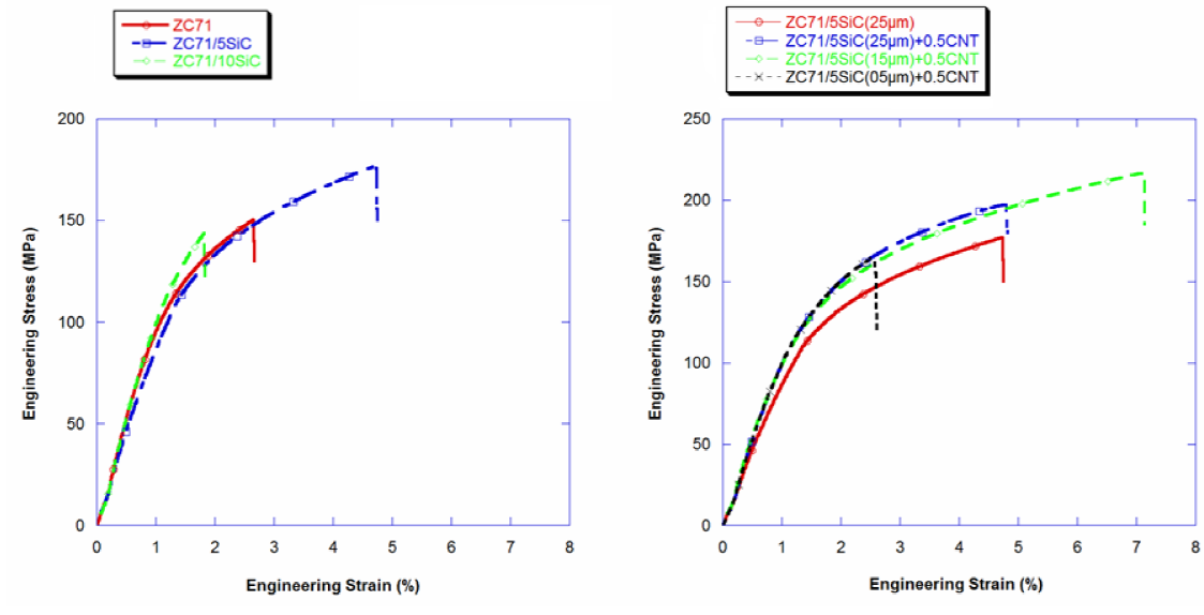
Figure 9 Variation of UTS and El% of ZC71 alloy and MMCs with different compositions/particle sizes.
Based on Fig. 9 and Table 2, the values of UTS and El.% of ZC71 alloy are 150.6 MPa and 2.9%, respectively. By adding 5 wt. % SiCp, the UTS and El.% increased to 176.7 MPa and 4.8%, respectively, owning to grain refinement and uniform distribution of SiC particles in the ZC71/5wt. % SiCp composite. However, further increment of the SiC particles to 10 wt. % led to the decrement of UTS and El.% to 143.2 MPa and 2.2%, respectively. Generally, the ductility and strength are related to the factors that leads to the initiation and propagation of the cracks formed owning to joining of voids, such as stress concentration during the tensile test (Wang et al., 2011). The microcracks and particle decohesion were formed by voids in the matrix (Wang et al., 2011). For the ZC71/5SiC+0.5MWCNT composite, initiation and propagation of the cracks may be affected by some factors: (i) defects during casting, such as oxidation surfaces and porosities; (ii) shape and distribution of the eutectic intermetallics; and (iii) size, form, and dispersion of the SiC particles and MWCNT and their bonding with the matrix (Li et al., 2009; Shang et al., 2014). Propagation of the cracks can be eased with the fragile interface of particles and matrix, while fine particles and grain boundaries can act as inhibitors for the cracks movement (Wang et al., 2011). Owning to the presence of casting defects and the semi-continuous network of intermetallics around the α-Mg phases, the ZC71 alloy displays relatively low strength and ductility, which can act as proper substrates for the microcracks initiation. Addition of 5 wt% SiC particles also enhances the strength and ductility owing to fine distribution of the SiC particles as well as grain refinement. Nevertheless, more SiC additions can speed up the agglomeration regions and strengthen the stress concentrations. For the ZC71/10 wt. % SiCp composite, the agglomeration of SiCp that led to the creation of stress concentration in these areas could act as proper sites for launching microcracks (Zhong et al., 1996). Furthermore, the weak interface of SiC particles and Mg matrix in the agglomeration regions could contribute in the cracks propagation and lead to composite failure. As a result, the strength of ZC71/10 wt. % SiCp was low. Furthermore, Fig. 8 depicts that by adding 0.5 wt. % MWCNT to the ZC71-5% SiC composite, the strength of the composite increases. As seen in Fig. 9 and Table 2, the UTS and El.% are 197 MPa and 4.7, respectively. Similarly, studies on the tensile strength of Mg composites show that the increase in the amount of reinforcement culminates in the increment of composites’ tensile properties (Aravindan et al., 2015). The key strengthening mechanisms as the result of MWCNT addition are grain refinement of the matrix alloy, load transfer, work hardening and particles strengthening (Ye & Liu, 2004). The MWCNT with finely dispersion (Fig. 5(e) , Fig. 5(h) and Fig. 5(k) ) blocked the dislocation motion within the composite, which strengthened the Mg matrix. In addition, the strength was improved by smaller-sized grains (Fig. 5(f) , Fig. 5(i) and Fig. 5(l) ), which expedited the composites’ tensile properties improvement at room temperature (Pal et al., 2010). The tensile properties of ZC71-5%SiC-0.5% MWCNT hybrid composite were also affected by the size of SiC particles. As shown in Fig. 8 and Fig. 9, the ZC71-5%SiC-0.5%MWCNT hybrid composite with SiC particle size of 15 µm had the highest tensile properties compared to the composites strengthened with SiC particles at 5 µm and 25 µm, respectively. As depicted in Fig. 9, the UTS and El.% of ZC71-5%SiC-0.5%MWCNT hybrid composite with SiC size of 15 µm are 216 MPa and 6.9, respectively. The UTS and El.% of ZC71-5%SiC-0.5%MWCNT hybrid composite decreased to 197 MPa and 4.7 when the SiC size was 25 µm, and further reduced to 150 MPa and 2.7% when the SiC size was 5 µm. As mentioned earlier, the grain size reduction for ZC71-5%SiC-0.5% MWCNT hybrid composite with SiC size of 5 µm was more predominant than hybrid composite reinforced with bigger SiC particle size (Fig. 5). The tensile strength and elongation should be higher than the hybrid composite with bigger SiC size, however, the hybrid composite with SiC particle size of 5 µm revealed the lowest tensile properties. This was owing to the agglomeration of SiC particles in some areas in the composite matrix as seen in Fig. 3, Fig. 5(j) and Fig. 5(k) . In fact, smaller reinforcement particles have a higher contact surface area than bigger particles, as a result, the tendency of smaller-sized particles to agglomerate and propagate crack is higher even though the crack movement is inhibited by grain boundaries and fine particles (Shang et al., 2014). Therefore, the size of reinforcement particles plays a significant role on the tensile properties of composites.
3.3. Fracture behavior
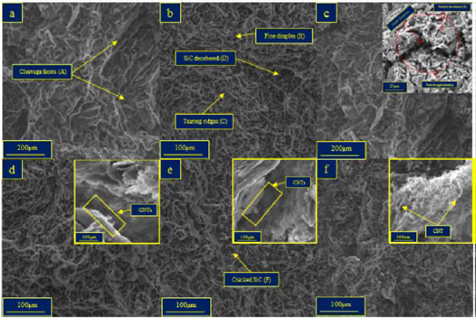
The fracture surface of ZC71 alloy illustrates the brittle fracture characteristics (Fig. 10(a) ) in which the cleavage planes (marked with A) are present on the fracture surface. Cleavage planes with steps show the brittle fracture. The brittle fracture mode of ZC71 alloy was due to the initiation of microcracks as a result of the presence of casting defects. Intermetallic compounds with a semi-continuous network in the matrix resulted in low strength and ductility. Hard and brittle IMCs augment the mechanical properties of the Mg matrix which is soft, ductile can deform elastically. The addition of 5 wt. % SiCp to the ZC71 alloy changed the fracture mode from brittle to quasi-cleavage fracture as shown in Fig. 10(b) . Fine dimples (marked with B), which are the pocket-like regions surrounding the fractured, and deciphered SiCp termed as ‘tear ridges’ were marked with C and a few decohered particles (marked with D) were present on the fracture surface. Fig. 10(c) shows the fracture surface of ZC71-10 wt. % SiCp. Cleavage planes and decohered particles (marked with E) can also be seen on the fracture surface. Owing to the weak interface bonding between the particles and matrix particles, decohesion occurred, which was a characteristic of brittle fracture in the composites. Furthermore, the development of a resultant triaxial stress state in the matrix assisted in limiting the flow stress of the composite (Manigandan et al., 2012). The rupture of the composite at low ductility was the result of the weak interface between the particles and matrix, which could not transfer the load from the matrix to the reinforcing particles (Babout et al., 2004). Fig. 10(d) illustrates the fracture surface of the ZC71-5% SiC-0.5% MWCNT hybrid composite with SiC particle size of 25 µm. As observed, the fracture surface revealed both ductile and brittle mechanisms, which were the characteristics of the quasi-cleavage fracture state. The fracture surface of the ZC71-5% SiC-0.5% MWCNT hybrid composite when the SiC size was 15 m is revealed in Fig. 10(e) . As observed in the figure, the fracture surface has some cracked SiC particles (marked with F), showing the high bonding strength between the particles and matrix. This leads to increasing value of UTS and El.% (Fig. 9). Furthermore, the “tear ridges” are observed on the fracture surface which indicates more ductile failure compared to the ZC71-5% SiC-0.5% MWCNT hybrid composite with 25µm SiC size. However, when the SiC size was decreased to 5 µm, the fracture behavior changed to brittle fracture (Fig. 10(f) ) in the ZC71-5% SiC-0.5% MWCNT hybrid composite due to high volume fraction of hard particles. Compared with the ductile region, decreasing of SiCp size leads to increasing of the brittle fracture region.
3.4. Wear properties
Fig. 11 illustrates the wear rate of ZC71 alloy and composites strengthened with SiC and SiC+ MWCNT. As observed, with the addition of 5wt. % SiCp, the wear resistance increased when the wear rate of ZC71 alloy was decreased from 5.66 mm3/km to 5.40 mm3/km. This improvement was the result of the load bearing capacity of the composites by ceramic particles during sliding. This was similar to the results reported by Pillai, et al., (2017) in Mg-TiO2 magnesium matrix composite, where, the addition of 5 wt. % TiO2 into the Mg matrix improved the wear resistance of the composite. The improvement owned to production of better adhesion between the matrix and particles with the addition of reinforcement particles, which in turn resulted in enhanced resistance to delamination. With the addition of 10 wt. % SiCp to the ZC71 alloy, the wear resistant was supposed to increase, however, as seen in Fig. 11, the wear rate increased to 6.08 mm3/km, causing the increase in material removal. The decrease was attributed to the non-uniform dispersion of SiC particles in the matrix alloy (Fig. 3(e) and Fig. 3(f) ). The SiC particles agglomerated in some areas and could not resist against the applied load during sliding. Furthermore, during the sliding wear test, the agglomerated SiC particles could be easily pulled out from the matrix and were entrapped between the pin and the counterpart, causing the occurrence of the ‘three-body’ wear, which resulted in the substantial wear rate (Ghandvar et al., 2018) (Fig. 11). The influence of MWCNT on wear behavior is shown in Fig. 11. With the addition of 0.5wt. % MWCNT to the ZC71-5%SiCp composite when the SiC size was 25 µm, the wear rate decreased to 5 mm3/km. The improvement in wear resistance with the addition of MWCNT could be attributed to the increase in hardness in which the hardness of the ZC71 alloy and ZC71 reinforced with 5%SiC composite increased to 62 HV after the addition of MWCNT (Table 2). The connection between hardness and wear rate can be explained by the Archard’s law, which describes an inverse proportionality between hardness and the wear rate of a material. Based on the Archard equation (Eq. 1), the composite’s wear rate is proportional to its hardness:
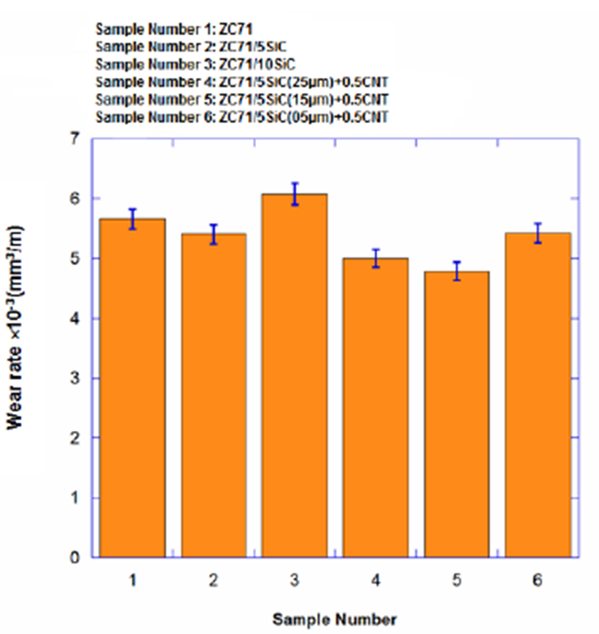
Where, Q is the wear rate (mm3/km), W is the volume of worn material per distance, K is a constant called wear coefficient and H is the hardness of the specimen in Vickers scale (kgf/mm2) (Archard, 1953). Another reason for the decrease in the wear rate of the composite owing to the addition of MWCNT was the existence of a strong bonding between the SiC and MWCNT with the ZC71 alloy matrix (Fig. 6) that facilitated the load transfer from the matrix to the hard particles (Basavarajappa et al., 2006; Miyajima & Iwai, 2003). Therefore, the strength of the composite was improved, in which, its plastic deformation resistance increased and the ploughing effect of the counter material on the matrix decreased, leads to a lower wear rate compared to the parent metal (Milan & Bowen, 2004). Variation of the SiC particle size was another parameter that influenced the wear behavior of ZC71-5%SiC-0.5%MWCNT hybrid composite. As seen in Fig. 11, the AZ61-5%SiC-0.5%MWCNT hybrid composite with SiC size of 15 µm had the highest wear resistance compared to other hybrid composites with SiC particle sizes of 5 µm and 25 µm. It was expected that during the wear test, the hybrid composite’s wear rate with finer SiC size (5 µm) would decrease because grain boundary strengthening occurs with smaller particle size, thus leading to strain hardening (Thakur & Dhindaw, 2001). However, the wear rate was significant. The high wear rate of ZC71-5%SiC-0.5%MWCNT was as a result of agglomeration of the SiC particles in the matrix (Fig. 5(j) and Fig. 5(k) ), which resulted in the ‘three-body’ wear during sliding and increment of composite’s wear rate. Additionally, due to the fragile bonding between SiC and matrix in the agglomerated regions, the SiC particles were unable to support the applied load efficiently. Therefore, the interface offered a site for crack nucleation and tended to pull out the particles from the wear surface, which led to the formation and propagation of crack in the subsurface wear region. Nevertheless, in the ZC71-5%SiC-0.5%MWCNT hybrid composite with SiC size of 15 µm, uniform distribution of SiC particle and good bonding of SiC and MWCNT with the matrix, the wear resistance was higher than that of hybrid composites with SiC sizes of 5 µm and 25 µm as shown in Fig. 11. Compared to alloys, the composite’s wear resistance could be associated with the favorable distribution of small-sized particles (Thakur & Dhindaw, 2001).
3.5. Friction coefficient
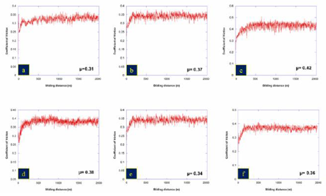
Fig. 12 illustrates the friction coefficient (µ) of ZC71 alloy and composites including SiC and MWCNT reinforcement particles. As seen in the figure, by adding 5wt. % SiC particles to the ZC71 alloy, the friction coefficient increased from 0.31 in ZC71 alloy to 0.37 in ZC71-5% SiC composite. The increase was due to the fact that as the harder SiC particles protruded from the softer Mg matrix, the friction coefficient value increased due to particle strengthening of the SiC reinforcement. From Fig. 12, it can be observed that with the addition of 10wt. % SiC particles to the ZC71 alloy, the friction coefficient further increased to 0.42. This increase was because in the ZC71-10wt. %SiC composite, the interfacial bonding between the matrix and SiC particles is poor. Thus, some of the pulled-out SiC particles fractured and led to increasing in the surface roughness by entrapping between the pin and counter-body which caused increasing in the friction coefficient. Furthermore, based on Fig. 12, it can observed that with the addition of MWCNT to the ZC71-5% SiC composite, the friction coefficient reduced. This might be due to the MWCNTs’ self-lubrication effect (Wu et al., 2015). During the wear test, the MWCNTs were pulled out from the matrix and could contact directly with the counter material, thus reducing the contact area between the matrix and the counter material. This led to a reduction in friction coefficient (Wu et al., 2015). Moreover, previous research (Dong et al., 2001; Kim et al., 2009; Scharf et al., 2009) proved that the wear surface could be covered by the formation of carbon film, which acts as a solid lubricant that lessens the friction coefficient. In addition, Fig. 12 displays the changes of friction coefficient of the ZC71-5%SiC-0.5%MWCNT hybrid composite with different sizes of SiC particle. As shown in the figure, the ZC71-5%SiC-0.5%MWCNT hybrid composite with SiC size of 15 µm had the lowest friction coefficient (µ=0.34) compared to other hybrid composites with SiC sizes of 5 µm (µ=0.38) and 25 µm (µ=0.36). Moreover, it has been reported that the friction coefficient of Mg MMCs increases as the particle size of SiC particles in MMCs increases (Kim et al., 2009). However, as shown in Fig. 12, when the SiCp size decreased to 5 µm, the friction coefficient increased. This was due to the significant contact between the rigid particles and the counterbody material caused by the pull-out of agglomerated SiCp.
3.6. Worn surfaces
Fig. 13(a) illustrates the ZC71 alloy’s worn surface. The worn surface had several continuous grooves parallel to the sliding direction. Moreover, in the ZC71 alloy with lower hardness (Fig. 7), the counterfaces between the pin and the sample surface increased, hence, more materials were detached from the sample’s surface. This detachment may be due to the adhesive friction that consequently increased the wear rate (Fig. 11). The principal wear mechanisms of the samples were abrasion and delamination wear. Meanwhile, the flake or sheet-like wear debris (Fig. 13(b) ) gathered from ZC71 showed delamination as one of the principal wear mechanisms. Thus, a greater wear was produced. It is obvious from Fig. 13(c) that by adding 5wt. % SiC particles to the ZC71 alloy, the groove width decreased, illustrating a mild abrasive wear mechanism. This showed an improved condition for wear behavior (Fig. 11). Fig. 11(d) demonstrates the presence of small-sized wear debris, indicative of the mild abrasion wear. On the other hand, as its observed in Fig. 13(e) , by adding 10 wt.% SiCp to the ZC71 alloy, deep parallel grooves with large width were indicatives of a severe abrasion, which is regularly produced by the existence of rigid particles between the pin and disc that cut into the worn surface. As observed in Fig. 3(e) and Fig. 3(f) , the introduction of a high percentage of SiC particle (10wt. %) SiCp to the ZC71 alloy caused the SiC particles to agglomerate in some regions in the matrix with a non-uniform distribution. Therefore, during the sliding wear test, the agglomerated SiC particles were pulled out from the matrix and became entrapped between the pin and disc. Next, abrasion took place, leading the material to be omitted from the abrasion groove (Fig. 13(e) ). The predominant wear mechanisms were severe abrasion and delamination. Fig. 13(f) depicts the intense separation of sheet-like delaminated wear debris for the ZC71-10wt. %SiC composite. The effect of MWCNT addition on the worn surface of the ZC71-5%SiC-0.5%MWCNT hybrid composite is illustrated in Fig. 13(g) . Based on the worn surface, the grooves became narrower and shallower after the addition of MWCNT, which could be due to the combination of high modulus and thermally stable MWCNT that increased the inherent hardness of the composite and resisted the material flow during sliding (Mondal & Kumar, 2009). To produce better wearing resistance and smooth worn surface during sliding, MWCNTs played an important role as a lubricant at the sliding interface between the sample and the counterbody because their network structure dispersed on the sliding surface (Umeda et al., 2009). Therefore, the amount of plastic deformation of the matrix was smaller in the ZC71-5%SiC-0.5%MWCNTs hybrid composites compared to the ZC71-5% SiC composite (Wei et al., 2013; Zhou et al., 2017). Examination on the wear residue disclosed the existence of small fragments and ribbon-like strips of materials (Fig. 13(h) ) because of abrasion. The influence of SiC particle size (5 µm and 15 µm) on the worn surface of ZC71-5%SiC-0.5%MWCNT hybrid composite is illustrated in Fig. 13(i) −Fig. 13(l) . Based on the worn surface of ZC71-5%SiC-0.5%MWCNT, when the SiC size was 5 µm (Fig. 13(i) ), the predominant wear mechanisms were abrasion and micro ploughing. At the commencement of the wear test, the metal matrix that surrounded the hard SiC and MWCNT was abraded. Consequently, the matrix was not able to maintain the agglomerated SiC particles and caused the particles to be detached from their site. The matrix alloy is contaminated by separated reinforcement particles and produced scratch marks. The contribution of smaller reinforcement particles to friction was more in the unit area, thus, in this study, more friction marks were created. Therefore, the influence of friction force on each particle was decreased. As observed in Fig. 13(j) , the wear debris is a mixture of small fragments and sheet-like particles. This confirms the aforementioned wear mechanisms. However, by increasing the size of SiC particles in the ZC71-5%SiC-0.5%MWCNT hybrid composite to 15 µm, the wear scratches (grooves) became smaller (Fig. 13(k) ) compared to the hybrid composite reinforced with SiC particle of 5 µm and 25µm. Thus, it can be said that a stronger association between the reinforcement particles and matrix can lead to a relatively lower damage permanency on the matrix. In general, separating of smaller particles from the matrix is more difficult. Therefore, smaller wear debris was produced during sliding as seen in Fig. 13(l) .
4. Conclusions
The effects of different SiCp addition, MWCNT with various sizes of SiCp on the macrostructural, microstructural, mechanical and tribological properties of ZC71 alloy were examined. It can be concluded that:
(1) The ZC71 alloy’s microstructure consists of α-Mg phase, which is enclosed by the semi-continuous network of the MgZnCu and Mg(Zn,Cu)2 intermetallics. With different SiC addition, the macrostructure of ZC71 alloy exhibited the formation of nearly equiaxed grains, and grain refinement with increasing SiC addition.
(2) With the addition of 5 and 10 wt. % SiCp, the grain size of ZC71 alloy decreased from 325.5 µm to 123.9 µm and 33.7 µm, respectively. Further reduction in grain size was achieved with the addition of MWCNT (112 µm) and size reduction of SiCp to 5 µm (55 µm).
(3) The Vickers hardness value of ZC71 alloy was 42 HV. The Vickers hardness value of the ZC71-5%SiC-0.5%MWCNT hybrid composite when the SiC size was 5 µm was 66 HV. This illustrates the effect of the appropriate choice of reinforcement particles and SiC size on hardness value.
(4) The tensile result showed that the best level of SiCp was 5wt. % in which the UTS and El.% of the ZC71 alloy increased from 150MPa and 2.9% to 176MPa and 4.6% in the ZC71-5wt. %SiCp composite, respectively. The UTS and El.% values of the cast ZC71 alloy increased to 197 MPa and 4.7%, respectively, with the addition of MWCNT to the ZC71-5%SiC composite. The values further increased to 216MPa and 6.95% in the ZC71-5%SiC-0.5%MWCNT hybrid composite when the size of SiC was 15 µm. The mechanisms of strengthening of the composites were load transfer effects, dislocation strengthening, and grain refinement.
(5) Examination on the fracture surface revealed that the fracture of the ZC71 alloy was quasi-cleavage (including some cleavages and dimples). With the addition of 5 wt. % SiC particles, the fracture surface owned more dimples and disclosed more quasi-cleavage fractures. By adding MWCNT to the ZC71-5% SiC composite with SiC size of 15 µm, the hybrid composite mainly presented the domination of the ductile fracture.
(6) The results of the sliding wear test showed that by adding 5wt. %SiCp to the ZC71 alloy improved the wear resistance of the alloy by decreasing the wear rate to 5%. Moreover, the addition of MWCNT to the ZC715%SiC composite with SiC particle size of 15 µm revealed the greatest wear resistance. The wear rate of the ZC71 alloy also decreased to 15%. The enhancement in wear resistance was due to the self-lubrication function of MWCNT, uniform distribution of SiC particles and good bonding of SiC and MWCNT with the matrix, which in turn decreased the friction coefficient of the composite.
(7) Examination on the worn surface revealed that the governed wear mechanisms of the ZC71 alloy were abrasion and delamination, which changed to mid abrasion in the ZC71-5%SiC-0.5%MWCNT hybrid composite when the SiC particle size was 15 µm.

