


 text new page (beta)
 English (pdf)
 Article in xml format
 Article references
 Send this article by e-mail
 Cited by SciELO
  Similars in
SciELO
Similars in
SciELO 
 Permalink
1. Introduction
Mirror products have become necessities in our everyday life and major materials for construction, manufacturing, and electronic industries. Auto mirrors allow light to be reflected so that the objects behind the car can be seen. Curved auto mirrors can make the driver’s rear view to appear to be wider. The side and rear auto mirrors are among the most important safety features on vehicles. In the manufacturing stages of auto mirrors, certain tasks, for examples: baking, electroplating, edging, etc., operated unusually, will cause scratches, chips, pinholes, bubbles and damaged edges on the general surface and profile faults on auto mirrors. These appearance faults sometimes will severely have an impact on the standard of the auto mirror reflection and grow the steering hazard. During the traditional examination of auto mirrors in the manufacturing process, almost all work is performed by human examiners. The manual examination can be easily affected by foreign objects reflected on the mirror surfaces, causing mistaken determinations of fault examination.
Figure 1 shows a regular side mirror of a vehicle and different styles of various auto mirrors.
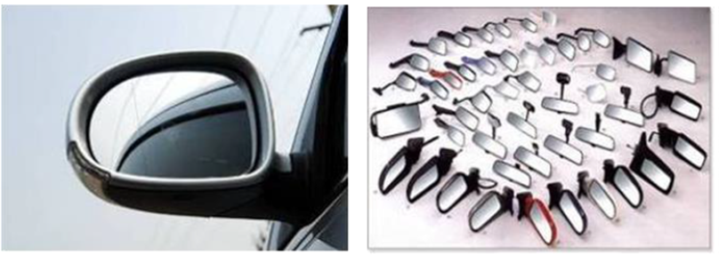
General auto mirrors manufactured of transparent glass with aluminum or chromium coated materials have a good ability of high reflectance and they with curved and convex shapes have a wider field of view. Regular appearance faults of auto mirrors comprise scratch, bubble, chip, pinhole, belonging to the surface fault type; and broken edges, burrs, belonging to the profile fault type. The appearance faults influence not only the visual quality of mirror parts but also their performance, effectiveness, structural strength, etc. The fault sizes of usual auto mirrors detected are at least wise 0.20 mm and 0.26 mm for the surface fault type and the profile fault type, respectively. Figure 2 shows a workpiece of auto mirror with dimensions and two equal size images captured from a testing sample. Two laser marks, including a sketch and some texts, are located on the mirror workpiece. The mirror workpiece having 18.1 cm in length, 10.71 cm in width, and 0.2 cm in thickness, needs to be scanned into two images to obtain better image resolution for further process to reach the industry standard requirement in appearance inspection of auto mirrors. Appearance faults on curved surfaces are hard to be censored for practical examiners owing to not only fault attributes but also light reflection on mirror exteriors. Figure 3 illustrates some general sorts of appearance faults on auto mirrors: (a) scratches, (b) chips, (c) pinholes, and (d) broken edges.
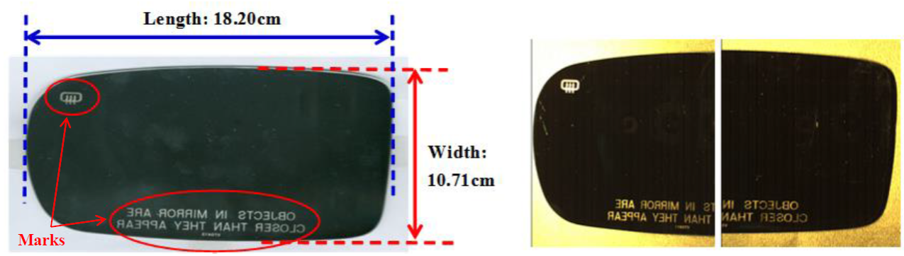
Figure 2 (a) Dimensions of a mirror workpiece; (b) two equal size images captured from a testing sample.
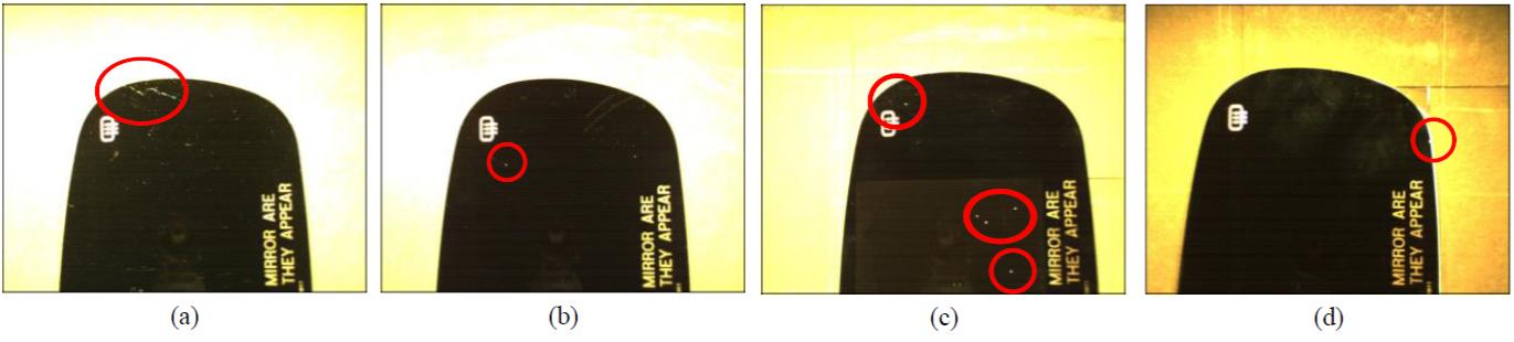
Figure 3 Some general sorts of appearance faults on auto mirrors: (a) scratches, (b) chips, (c) pinholes, (d) broken edges.
Auto mirrors are being produced in curved convex shapes for obtaining wider field of views, which grows troubles of examining the products. The traditional inspection skill for appearance faults on auto mirrors is manual inspection by human eyes. Mirror examination requires particular working facility with special lighting control system. In the real working area, every testing mirror is carried into the examiner’s field of vision. An auto mirror is a rectangle form having four circular corners and curve surface. Most of the appearance faults could be found on the surfaces of mirrors. The curved mirrors have the appearance of higher reflectance and wider field of view in spatial domain images which are more intricate than those of the plane auto mirrors. It is more difficult to exactly identify appearance faults inlaid on the curved surfaces.
Visual examination by operators is boring, laborious and highly dependent on the inspectors’ expertise. Mistaken discernments can be simply made because of the inspectors’ eye exhaustion and subjectivity. Because auto mirrors have high reflective appearances, these reflected lightings make the fault inspection work more difficult when appearance faults are embedded on the uneven exteriors of auto mirrors. Higher reflection on uneven exteriors grows the difficulty of differentiating the appearance faults on auto mirrors. The suitable lighting control technique of acquiring images provide the possibility to execute automatic fault inspection. Figure 4 shows some preliminarily processed images of a captured testing sample, including initial intensity images, binary images by Otsu method (Otsu, 1979), and binary images by manual thresholds. Many appearance faults are found and the laser marks are also mixed up with faults in the binary images. Furthermore, when workpiece images are being acquired, the region of a surface fault could extend, reduce or even vanish due to unbalanced lighting of the circumstance, different view angles of the inspectors, shapes of reflected patterns, and so on. Thus, this study conducts an automated appearance fault detection system of auto mirrors to substitute visual examination workers from inspection works of auto mirrors. This study recommends a fault enhancement technique based on Fourier high-pass filtering and the convex hull arithmetic to examine appearance faults on curved mirrors of vehicles.
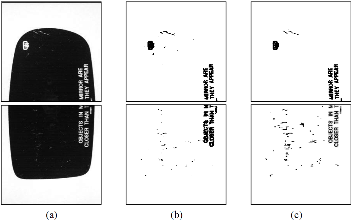
Figure 4 Preliminarily processed images of a captured testing sample: (a) initial intensity images; (b) binary images by Otsu skill; (c) binary images by manual thresholds.
The remainder of this article is arranged as the following: Firstly, we discuss the related studies on optical techniques for fault inspection. Secondly, we describe the proposed image models for detecting appearance faults on auto mirrors. Thirdly, we perform the trials and appraise the manifestation of the recommended method with existing skills. Lastly, we make some conclusions and indicate the further directions.
2. Materials and methods
Automated visual inspections of surface flaws have changed into pivotal tasks for manufacturers endeavoring to promote product quality and manufacturing efficiency (Kuo et al., 2018; Taha et al., 2014). Lin et al. (2013) proposed using image reconstruction method based on cosine transform to inspect small appearance variations on capacitor chips of electronic elements. Park et al. (2016) modelled lots of parameter combinations for deep learning networks with distinct depths and layer nodes to take proper configuration for automated inspection of exterior blemishes on textured and non-textured elements. Lin et al. (2019) utilized some novel convolutional neural network models having deep learning skills to inspect flaws on light-emitting diode (LED) chips.
Several investigations report the automatic appearance flaw detection of glass-related products. Lin and Tsai (2012) introduced a rebuilt scheme based on Fourier domain to detect linear flaws on capacitive touch panels. Li et al. (2014) used the principal components analysis theory to detect visual faults on the cover glass of mobile phones. Lin and Li (2017) implemented a fault inspection system with the wavelet domain-based filtering method to detect area flaws on touch panels. Chiu and Lin (2013) integrated Hotelling’s distance function and grey theory based on discrete cosine domain to detect surface faults on transparent lenses of LEDs. Lin and Chen (2019) incorporated the partial least squares theory in the wavelet packet domain for surface flaw inspection on textured LED lenses.
Certain research even more concentrated on exploring the visual fault detection of mirror goods. Chiu et al. (2017) developed an optical distortion detection skill based on Hough domain for automatic flaw detection on clear glass of vehicle mirrors. Lin and Hsieh (2018) implemented a visual inspection system having small-shift detection schemes to find reflected distortion flaws on curved vehicle mirrors. The distortion type of defects makes reflected objects look irregular, out of focus, and blurry on the car mirrors. Chiu et al. (2020) proposed the image models based on 1-D Fourier descriptors to detect profile flaws on vehicle mirrors. The profile type of defects, such as damaged edges and burrs, changes contour shapes of car mirrors and may reduce the ability to withstand stress. From the previous commentary of articles, most of the present studies concentrate on automatic flaw detections of transparent glass, optical lenses, and mirrors. Those optical inspection systems focus mostly on the distortion and profile blemish detections. Since appearance faults sometimes have an impact on not only the visual quality of industrial parts but also their functionality, efficiency, structural strength, etc. (Da et al., 2018), the degree of harm even more than the distortion and profile faults. Less studies explore appearance inspections with attributes of little flaws on curved surfaces of auto mirrors. Consequently, we apply the Fourier high-pass filtering and convex hull arithmetic to inspect appearance faults on high reflective surfaces of auto mirrors.
Automated thresholding skills have been large exploited in the applications of machine vision for automated visual detection of flaws (Sezgin & Sankur, 2004). The Otsu (1979) method is one of the superior threshold choice skills for ordinary actual industrial images concerning consistency and form measures. It chooses the thresholding value maximizing the between-class variances of the image histogram. This chosen value is optimum for thresholding major targets from the background. The method offers adequate outcomes for thresholding an image having a bimodal distributed histogram. Ng (2006) modified the Otsu approach for choosing optimum thresholding values for unimodal as well as bimodal distributions, as well as examined the manifestation of the improved technique on general flaw inspection implementations. Truong and Kim (2018) further combined the Otsu method and entropy weighting scheme to detect surface defects of wafers.
Wavelet transform and Fourier transform are the most general pattern recognition techniques employed in frequency domain. The wavelet transform permits a spatial-frequency decomposition of the feeding-in signal and level of frequency resolution in wavelet domain is classically contemplated very coarse for experiential spatial-frequency analysis (Mallat, 1989). Lin (2007) combined the multivariate statistical method in wavelet domain to detect ripple flaws with low gray-level contrast on surfaces of ceramic components. Ngan et al. (2005) addressed a decomposition method in wavelet domain to detect visual flaws in periodically textured fabrics. This approach applied the wavelet transform to breakdown a testing image, and then used the automatic thresholding to the high-frequency sub-images for separating flaws. Li (2009) applied a filtering method in wavelet domain to strengthen flaw areas and extract discriminative properties from rebuilt images and the support vector machine classifier to classify five main flaw types on copper surfaces.
Fourier transform is insensitive to noises and unvarying to translation, rotation, and scaling, which makes it a perfect selection for automatic flaw inspection in the production process. Chan and Pang (2000) defined two diagrams, the central spatial and frequency spectrums, based on the Fourier transform to analyze fabric faults. Da et al. (2018) developed a quantitative inspection method in Fourier domain applying directed ultrasonic waves for efficiently detecting flaws in pipeline structures. He et al. (2015) used an optical measurement method based on Fourier transform profilometry to recover the rail profile and flaws on the rail web. Tsai and Huang (2019) introduced an image rebuilt method in Fourier domain to inspect and locate little flaws in homogeneous pattern images of electronic surfaces. The flaw inspection arithmetic used in the spatial images are normally reactive to noises, lighting changes, and geometric variations.
To obtain a whole boundary shape of a convex auto mirror, the convex hull of an auto mirror need be computed to yield the smallest convex polygon containing the mirror. The convex hull is a basic structure for mathematics and computational geometry. Because it is an accurate description of the boundary of a point set, the calculation of convex hull of a point set has favorably been employed in many application fields, such as data mining, geographical information systems, pattern recognition, image processing and medical simulations (Jayaram & Fleyeh, 2016; Yang & Cohen, 1999). Most of the existing methods take the coordinates of data points as input and produce the vertices and faces of the convex hull polytope. These methods can be divided into two types: exact methods and approximate methods. The exact methods can compute the convex hull of a given set exactly, while the approximate methods find a rough convex hull. For some applications, an approximated convex hull is needed instead of the exact one. If the exact convex hull contains too many vertices, the computation cost of the exact solution is very high.
The earliest exact method is the gift-wrapping algorithm for two dimensional inputs proposed by Chand and Kapur (1970) and Jarvis (1973) . A modified version developed by Graham (1972) sorts all the points in an increasing order of the angles that the line segments between them and performs a more efficient searching scheme. Bentley et al. (1982) introduced the planar algorithms for hull construction, diameter finding, and hull searching to rapidly produce approximated hulls of controlled accuracy. The quick hull method proposed by Barber et al. (1996) divides the problem into many sub-problems recursively and solves them independently. Li et al. (2021) proposed a variational approach not only can calculate the multiple exact convex hulls simultaneously but also can be extended to compute the convex hull with outliers.
The Fourier transform based rebuilt method is a sturdy means for fault inspection in uniform mode, random texture, periodical pattern surfaces covering most of workpieces in manufacturing industry. The auto mirrors have near-convex shapes, the convex hulls of the auto mirrors can be used for removing noises from potential fault areas. Consequently, this study presents an image rebuilt scheme using Fourier high-pass filtering with cross-shaped filter and convex hull arithmetic to inspect small appearance faults on auto mirror images.
3. Suggested methods
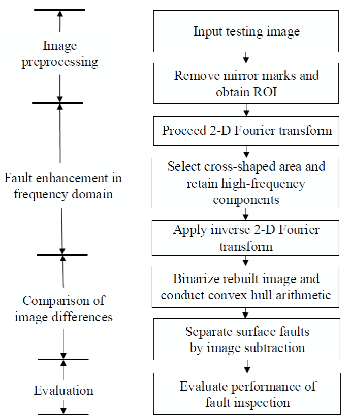
This study proposes an image rebuilt technique based on Fourier high-pass filtering and convex hull arithmetic to inspect appearance faults for vehicle mirrors. Five steps are developed to accomplish the procedure of appearance fault inspection. Firstly, image preprocessing is executed to remove laser marks and background region and produce a ROI and a merged image to reduce the obstruction of non-mirror regions in further frequency analyses. Secondly, the merged image is transformed to Fourier domain as well as the appearance message of the trial mirror is converted to frequency spectrum. Thirdly, by selecting a proper filtering width in frequency domain, the high-frequency parts outside the central cross-shaped region are retained and the remainders are given to zero for reconstructing the object appearance. There is detailed message regarding faults and edges in the preserved high frequency elements than those in the low frequency elements. Fourthly, the filtered frequency image is executed by the inverse Fourier transform to make a reconstructed image. Thus, a fault-enhanced image could be reconstructed from the frequency domain for contrasting with the pre-processed image. Fifthly, the convex hull arithmetic is applied to remove noises for detecting appearance faults. Therefore, the appearance faults on the curved auto mirrors can be exactly identified and located by the proposed approach. Figure 5 describes the flow chart of the suggested method.
3.1. Image preprocessing operations
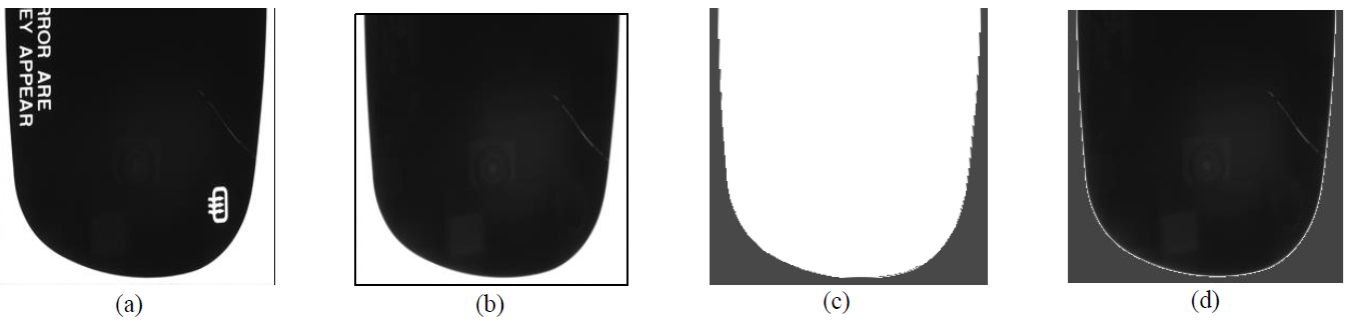
For acquiring finer image resolution and fault inspection manifestation, a testing trial is partitioned into 2 portions for image capture. Thus, the whole testing trial is evenly acquired into 2 testing images to obviously exhibit the contents of object surfaces and boundaries on both images (Figure 2). Since the locations of the laser marks are fixed and known relative to a whole auto mirror, two pre-defined rectangular blocks containing the marks are used to remove the laser marks from the testing images (Figure 2(b)). In this study, we define a ROI (region of interest) in a square block including the objects will be explored. The adoption of ROI avoids unconcerned regions from obstructing neighborhood calculations or mathematical transformations. If an image having unconcerned districts is converted to a frequency domain, the unrelated regions can notably obstruct the frequency analysis of the interested objects. Therefore, after the area of background and the desire object without marks are obtained, we will produce a mask to depict the mirror area called ROI (Figure 2(c) ). Then, we acquire a merged image by integrating the mirror area with an operated background (average intensity of the mirror area) to decrease the obstruction of the initial background. This merged image could be applied as the source for Fourier transformation. Figure 6 displays the outcomes in the operations of image pre-progressing for a normal sample: (a) initial image; (b) mark-removed image; (c) ROI image; (d) fused image. With such an operated background, we acquire a rectangular block for Fourier transform as well as minimize the obstruction of non-mirror regions.
3.2. Fourier high-pass filtering
Fourier transform possesses the advantageous attributes of noise-resistivity and increase of periodic properties (Gonzalez & Woods, 2017; Chan & Pang, 2000). The Fourier domain portrays the textured image expressed as frequency parts. These entire textured patterns are simply discernible as gathering of low-frequency coefficients with large energy in the spectrum. Suppose f(x, y) be an intensity located at coordinates (x, y). If an image with size of M × M pixels, the two-dimensional DFT (discrete Fourier transform) of f(x, y) can be defined as (Gonzalez & Woods, 2017),
where
The size of the transformation is concentrated on the origin of the Fourier frequency image.
The directional attributes of an intensity image obviously correlate with low frequency coefficients having high energy, which are dispersed on the unbent stripes in the Fourier frequency image with orientations orthogonal to their equivalents in the spatial domain image. If a mirror image with the vertical and horizontal edges of mirror boundary is converted to Fourier domain, two major stripes with low frequency coefficients having high energy cross at the middle of Fourier spectrum image.
Low frequency coefficients having high energy are related with regular line patterns may arise about the major stripes in the Fourier frequency image. For entirely removing all homologous line modes in the spatial domain image, not merely the frequency coefficients placing on the major stripes but those frequency coefficients in the vicinity of the major stripes as well need to be eliminated from the Fourier frequency image. These frequency coefficients dropping in the vicinity of the major stripes in the Fourier frequency image are essentially filtrated through assigning these coefficients to zero. Figure 7 shows the images and data matrices in the Fourier high-pass filtering process with cross-shaped mask. The upper part of Fig. 7 displays the processed images before and after the high-pass filtering applied. After completing the filtering task, a cross-shaped region with dark intensity is located in the central of the filtered frequency image. The lower part of Fig. 7 shows the handling of detailed data changes before and after the high-pass filtering conducted. This study will contrast the fault inspection manifestation of the suggested method with distinct filtering widths later. After filtering the specified stripe regions, we conduct inverse Fourier transform to obtain a filtrated reconstructed image in the spatial domain.
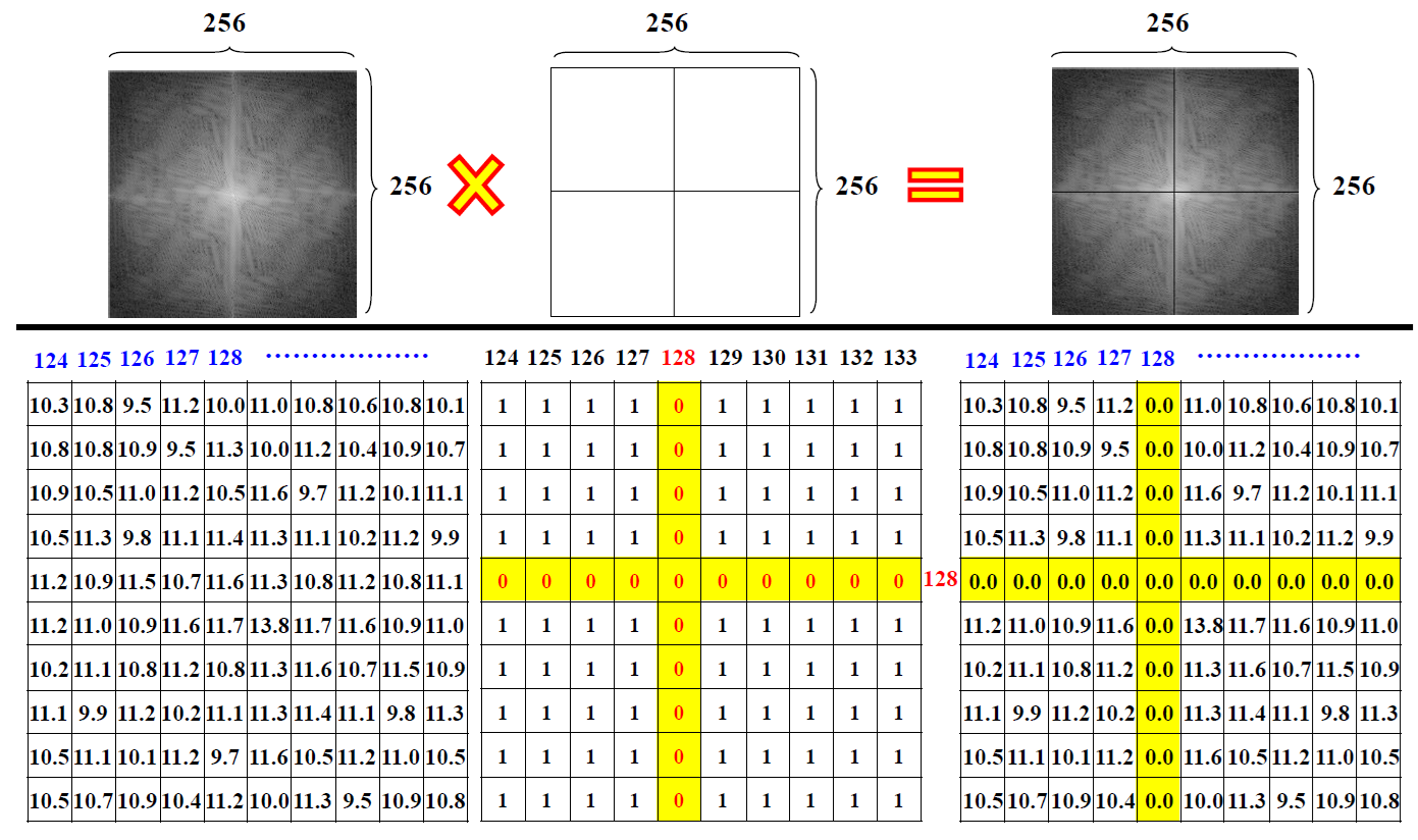
Figure 7 Images and data matrices in the Fourier high-pass filtering process with cross-shaped mask.
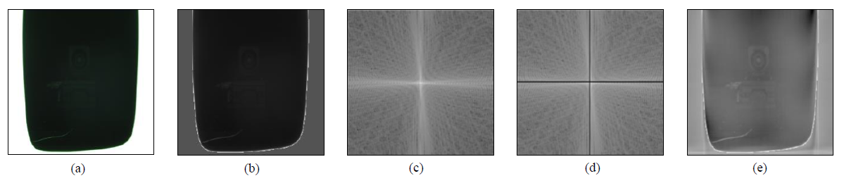
Figure 8 shows the results in the operations of Fourier high-pass filtering. Fig.8(a) is a testing faulty image; Fig. 8(b) is its pre-processed image; Fig. 8(c) is Fourier domain image; Fig. 8(d) is the high-pass filtered frequency image; and Fig. 8(e) is the corresponding filtered rebuilt image. After performing the reverse Fourier transform, the filtered rebuilt image displays more detailed appearance information than that in pre-processed image without the filtering. It can be seen that the rebuilt object retaining a large portion of the middle and high-frequency components displays clearer faults and appearance changes on the mirror surface. Moreover, if only a few portions of the low-frequency coefficients are filtered, the border between the object and the operated background becomes low-contrast, supplying an approach to enhance appearance faults. By selecting a proper filtering width, the low-frequency coefficients are filtered to enhance the appearance faults and get the filtered reconstructed image for comparison of image differences.
3.3. Convex hull and comparison of image differences
The filtered rebuilt image has consistent intensities for pixels pertaining to homologous regions of object and operated background, but it also produces notably distinct intensities for pixels pertaining to nonhomologous fault areas. The gray level changes in homologous districts could be very little, while the intensity changes in nonhomologous regions could be big contrast to the whole rebuilt image. Therefore, this study can determine a threshold for distinguishing faults from mirror area in the rebuilt image. The rebuilt image will be approximately a consistent intensity image if a non-fault appearance image is tested. The upper limit TU for intensity changes in the rebuilt image is expressed by TU = μ + Nσ, where μ and σ are the mean and standard deviation of the intensities of the rebuilt image f'(x, y), N is a controlled parameter decided by experiments. The binary fault image D(x, y) for fault separation is:
If a pixel with the intensity is less than the upper limit TU, the pixel is categorized as a homologous element. On the contrary, it is categorized as a fault element. When the fault sizes to be detected are usually very little contrast to the whole appearance image, the μ and σ can be counted straight from the rebuilt image of an initial image to tolerate the illumination changes in the examination circumstance.
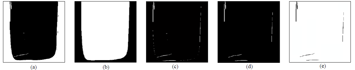
The binarized rebuilt image B(x, y) may have many false alarm pixels due to the inaccurate estimates of parameters μ and σ. Since the testing mirrors have near-convex shapes, the convex hull arithmetic is utilized to produce a convex hull image of the rebuilt image for removing the pixels of detecting usual districts as faults. The convex hull arithmetic (Graham, 1972) is applied in this research to the binary image to produce a convex hull image. Then, a XOR image obtained from the differences of taking exclusive OR operations between the convex hull image and binarized rebuilt image will significantly reduce the false alarm pixels. Since the fault sizes of usual auto mirrors need be inspected out are leastwise 0.20 mm and 0.26 mm for the surface and profile fault types, the too small detected fault pixels are regarded as noises and need be excluded. Figure 9 shows the results in the operations of comparisons of image differences. Fig. 9(a) is the binarized rebuilt image; Fig. 9(b) is the corresponding convex hull image; Fig. 9(c) is the XOR image; Fig. 9(d) is a small noise-removed image; and Fig. 9(e) is the final resulting fault image.
4. Experiments and discussion
4.1. Image acquisition
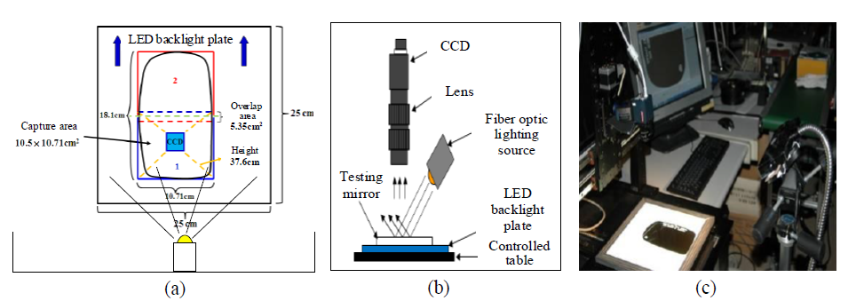
To intensify the clearness of object surfaces and contours on auto mirrors in the phase of image capture, this study utilizes the subsequent devices in the implemented inspection environment: a clear LED backlight tray having dimensions of 250 x 250 mm, a color charge-coupled device camera with 500M, a lens with 12 mm focal lengths, and an electronically controlled table. Figure 10 illustrates the schematic drawings (top view and side view) and the hardware configuration of image capture for acquiring a trial mirror. Assessments are performed on 90 real auto mirrors (30 faultless samples and 60 faulty samples) to appraise the representation of the proposed method. Every image including a half of an auto mirror has a size of 256 x 256 pixels with an intensity of 8 bits. The appearance fault detection algorithm is edited in C language and executed on the 6th version of C++ Builder complier on a computer (INTEL CORE i5-4210M 2.6GHz 4GB RAM).
4.2. Evaluation indices of inspection performance
To mathematically confirm the representation of the recommended technique, we differ the outcomes of our appraisals from those offered by practical assessors (ground truth). The expression guides, (1-α) and (1-β), are used to express proper inspection assessments; the larger the two guides, the more precise the inspection outcomes. False alarm mistake (α, regarding usual districts as faults) divides the regions of usual districts inspected as faults by the regions of actual usual districts to gain the mistake. Missing alarm mistake (β, failing to alarm actual faults) divides the regions of uninspected actual faults by the regions of all actual faults to obtain the mistake. For the both mistakes, the lower the guide values, the better the detection outcomes (Montgomery & Runger, 2007).
4.3 Selection of key parameters
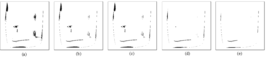
Choice of the key parameter, filtering width, in the Fourier high-pass filtering operation will significantly influence the inspection performance of appearance faults in the proposed method. To appraise the influence of altering diverse filtering widths on rebuilt results, tests show the manifestation guides of inspection outcomes by filtering widths from the range 1 to 4 pixels. Figure 11 shows the filtered Fourier frequency images and corresponding resulting outcomes with four filtering widths. Fig. 11(a) shows the pre-processed image and result by inspector. Table 1 presents the fault detection results for the four filtering widths in three performance indices. The figures demonstrate that too little the number of filtering width (e.g. 1) cannot adequately separate faults from the mirror appearances and leads to lots of incorrect alerts. However, too big the numbers of filtering widths (e.g. 3 and 4) produce the diverse effect of the faults and causes many missing alerts. The numbers of filtering width 2 is more appropriate to emphasize appearance faults in the Fourier high-pass filtering. Our trials on a variety of testing images have verified that filtering width 2 is ordinarily appropriate for this fault inspection application.
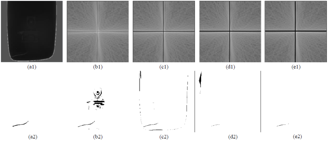
Figure 11 The filtered Fourier frequency images and corresponding resulting outcomes with various filtering widths: (a) pre-processed image and result by inspector; (b) filtering width 1; (c) filtering width 2; (d) filtering width 3; (e) filtering width 4.
Table 1 Contrast effects table of four different filtering widths.
| Filtering widths | False alarm rate α (%) | Fault inspection rate 1-β (%) | Correct classification rate CCR (%) |
| 1 pixel | 5.69 | 73.75 | 94.30 |
| 2 pixels | 0.63 | 86.59 | 99.36 |
| 3 pixels | 0.23 | 71.20 | 99.75 |
| 4 pixels | 0.32 | 74.32 | 99.67 |
In the procedure of comparisons of image differences, selecting a suitable manipulated parameter N (in Eq.(4)) leads to accurately differentiating faults from usual districts but an unsuitable manipulated parameter makes lots of mistakenly inspecting normal districts as faults. All trail samples revealed in this research are originated in the μ and σ from initial images, and the manipulated parameter N is assigned at various values. To assess the influence of changing various control values on the rebuilt results, tests show the manifestation guides of inspection outcomes by control values from the range 0.01 to 0.09. Figure 12 presents various places of the two-paired guides (α, 1-β) for the control values from scope 0.01σ to 0.09σ on the receiver operating characteristic plane (Montgomery & Runger, 2007). The curve indicates that smaller constant values (e.g. 0.01~0.05) makes a strict control and may lead to too many false alarms and a bigger constant value N (e.g. 0.09) makes a baggy control and may cause some missing alarms. The number of constant value 0.07 is more appropriate to stress appearance faults in the comparisons of image differences. The trials on a variety of testing images have confirmed that control value 0.07 is ordinarily appropriate for this fault inspection application. Figure 13 shows the outcomes of applying various control values to the binarization of the rebuilt images.
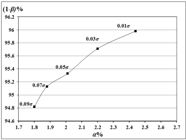
Figure 12 Various places of the two-paired guides (α, 1-β) for threshold values from scope 0.01σ to 0.09σ on the receiver operating characteristic plane.
4.4. Results of fault detection and comparisons with existing methods
Two existing schemes usually applied to anomaly detection is contrast to the recommended approach to differentiate effects of appearance fault inspection. To indicate the fault inspection outcomes of a testing image, Figure 14 demonstrates fractional outcomes of inspecting appearance faults by the Otsu method (Otsu, 1979) , the DFT filtering method (Lin & Tsai, 2012), the recommended method, and the ground truth provided by inspectors, separately. The Otsu method produces many of the erroneous judgments in regard to missing alarms and the DFT filtering method causes many of the erroneous judgments concerning false alarms on appearance fault inspection. The suggested method inspects most of the appearance faults and produces less erroneous judgments. Therefore, the suggested technique surpasses the Otsu method and DFT filtering method in the appearance fault detection of auto mirrors with high reflective surfaces.
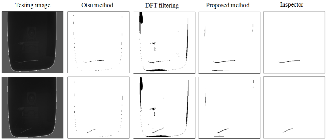
Figure 14 Detection outcomes of two testing images for auto mirror fault inspection by Otsu method, DFT filtering method, recommended method, and manual inspection.
Table 2 indicates the differentiating effects of appearance fault detection outcomes in the executed trials. One spatial domain technique and two frequency domain skills are assessed contrary to the consequences by practical assessors. The average fault inspection rates (1-β) of total trial samples by the three ways are, 67.75% by Otsu method, 72.26% by DFT filtering method, and 95.13% by suggested method. Nevertheless, the two existing techniques have notably larger false alarm rates (α), 25.33% by Otsu method, and 27.91% by DFT filtering method. Contrarily, the suggested scheme has quite smaller false alarm rate 1.88%. The suggested method has a larger correct classification rates (CCR), 98.11%, than do the other skills utilized to appearance fault detection of auto mirror images. More concretely, the suggested approach has a larger fault inspection rate as well as has a smaller false alarm rate utilized to auto mirror images having high reflective surfaces.
Table 2 Summary table of differentiating effects by three fault detection methods.
| Detection Schemes | False alarm rate α (%) | Fault inspection rate 1-β (%) | Correct classification rate CCR (%) | Processing time (sec) |
| Otsu method | 25.33 | 67.75 | 74.67 | 0.18 |
| DFT filtering method | 27.91 | 72.26 | 72.08 | 0.28 |
| Suggested method | 1.88 | 95.13 | 98.11 | 0.32 |
The average execution time for treating an image with 256 x 256 pixels is as the following: 0.18 seconds by Otsu method, 0.28 seconds by DFT filtering method, and 0.32 seconds by suggested method. The mean processing time of the suggested scheme is nearly two times larger than that of the Otsu method yet it can be improved for actual fulfillment of an automatic optical detection system through hardware enhancement. The suggested approach conquers the problems of detecting appearance faults on auto mirror images with reflective and curved exteriors and overbears in its capability of correctly discriminating appearance faults from usual districts.
5. Conclusions
This research seeks to examine the replacement of human inspectors in a production process by exploiting a frequency filtering method based on computer vision to inspect appearance faults on auto mirror products. This study suggests a fault enhancement technique based on Fourier high-pass filtering and the convex hull arithmetic to the optical inspection of appearance faults on high reflective surfaces of auto mirrors. Through comparing the testing image with the corresponding convex hull image, the suggested method does not need any standard pattern for template matching and there is no need for the accurate positioning of mirror workpieces in jigs. Trial outcomes show that the suggested approach increases by 95.13% the probability of accurately differentiating appearance faults and a low 1.88% probability of mistakenly detecting usual districts as appearance faults on reflective exteriors of auto mirrors. The proposed method effectively and efficiently overcomes the difficulties of detecting small appearance faults on auto mirrors with high reflective surfaces and excels in its ability of correctly discriminating faults from normal regions. Major restrictions of the present method require to be overcome as follows: it will produce more missing alarms if the appearance faults are gathering in a narrow scope, and it is not reactive to discriminate the appearance faults with slow variations in shape. Therefore, future research directions can focus on examining existing approaches to search for the most efficient and effective method for the proposed application.

