


 text new page (beta)
 English (pdf)
 Article in xml format
 Article references
 Send this article by e-mail
 Cited by SciELO
  Similars in
SciELO
Similars in
SciELO 
 Permalink
1. Introduction
Although the designers are always eager to create complex and creative designs, the difficulties in manufacturing such designs overweigh and limit these ambitions. These manufacturing difficulties root from the limitations and constraints associated with the use of tools among the conventional processes that hinder the creation of features such as undercuts, deep narrow channels, sharp junctions, and dramatic thickness and cross section changes. Therefore, the designers constantly work within a multidisciplinary team, at the early design stages, wherein they will be reminded of the available manufacturing capabilities that will be used to produce their designs. Adopting a concurrent engineering mentality helps to notably reduce and probably avoid any costly manufacturability, and assembly issues at downstream activities.
Due to the importance of manufacturability feedback for the designers, many methods have been developed overtime to improve the efficiency, quality and delivery of feedbacks ranging from manual Boothroyd and Dewhurst guidelines and worksheets to expert systems, software and advanced simulations. One example for such common tool is the DFMA software that was designed and built by Boothroyd and Dewhurst. In DFMA software, the designers manually enter all information about design to determine a particular design production cycle time and costing. Within Boothroyd and Dewhurst software, the user has to enter all information manually which necessitate user to have a good design and manufacturing knowledge or to be a professional designer (Boothroyd and Dewhurst DFMA software, n.d). Similar software’s such as a priori and other add-ins in some of the CAD software were also developed and mainly focused on costing, cycle time, in addition to enabling comparisons of different designs and depended on designer expertise to identify problems and modify designs (apriori, n.d; Xometry, n.d). Notably, these tools targeted professional designers and engineers and heavily relied on manual data entry. On the other hand, there were other tools developed with the capability of automatic locating of features/areas in the design that need modifications. Generally, these tools assess designs given a specific manufacturing process and provide the feedback in various forms. For example, some feedback can appear as warnings if features violate a set of predefined constraints (Cutkosky et al., 1993), or as a ranking of features according to their manufacturability where features with lower scores are possible candidates for redesign. Other tools relied on performing a complex manufacturability analysis of the design given a predefined set of capabilities in the light of a certain manufacturing process and providing results in textual format (Er & Dias, 2000; Lockett, 2005; Madan, Rao, & Kundra, 2007; Ravi, 2003) or as 3D colored feedback within the CAD system (C3P Software, 2015; DFMA, 2015), or as a portable 3D color-coded PDF (Hoefer & Frank, 2018; Traband, 2013). Overall, these tools were tailored based on their designers’ requirements (Gupta, Regli, Das, & Nau, 1997) and were process-related. Therefore, the efficiency of these tools in facilitating design modifications depends largely on the quality and comprehensiveness of the feedback and the ability of the designers to interpret it.
Recently, as a result of rapid technologies’s (RTs) emergence and swift development, many people claim that it is the era of highly complex designs, and that the DFM- based feedbacks are no longer crucial. Their claim is based on the fact that those technologies are layer-based wherein 3D models are sliced into 2.5D layers that are built in bottom up approach from powder, resin, and other materials. Being layer-based, tools (i.e., molds) are not needed in these processes to operate which eradicate fear of tool-related limitations and constraints common in the conventional processes. In other words, RTs provide designers with the freedom to design highly complex geometries and features that are usually non-producible. Thus, the DFM-feedback are no longer crucial. However, a recent study showed that RTs freedom is limited, particularly, when thinking about the advanced modeling skills and software required to create complex geometries (Abdelall, Frank, & Stone, 2018). The study showed that when the designers were asked to create ideas considering RTs as a manufacturing mean, they generated unique and complex geometries. However, these geometries led to two main problems; inability to create 3D electronic models, and designer violations of design constraints, which could probably lead to design failure and rejection at downstream activities. These problems shed light on the need for developing advanced modeling software suitable for making such geometries and brought to light again the importance of the team-based feedback for designer.
Moreover, the need for DFM-feedback will rise again when thinking about the future of parts produced by RTs. In other words, RTs have long processing time in addition to narrow materials choices, therefore, they are usually used for the development and design of new products or those with low volumes. If demand on RTs design spikes, as in the case of success of new design, there will be a need for modifying it to be producible by conventional processes to meet mass demands. A recent study showed that migrating designs between processes is not an easy task, especially, when the designs moved from RTs, usually rich with non-producible features, back to the conventional processes (Abdel-all, 2018; Abdelall et al., 2018). The difficultly emerges from the designer’s tendency to fixate on their original designs, and consequently inability to reconsider conventional processes’ limitations and constraints while modifying; hence, failure to make key design changes in non-producible features. A possible way to deal with this RTs related design fixation is through having a proper manufacturability feedback. Another recent study tried to present a design migration tool to help moving designs from RTs back to conventional processes through dissecting designs into manufacturable pieces. The migration tool utilizes the manufacturability feedback from one of new methods called ANA-machining to identify non-producible features and then define proper cutting lines that will guarantee manufacturability of resultant pieces by conventional processes. The machining feedback from ANA is a geometric based one; it is obtained based on assessing part visibility, reachability, accessibility and setups (Abdel-all, 2018). Thus, the solution suggested by the migration method is geometric based only; no other manufacturing aspects are considered such as production volume, material, tolerance, surface quality and others.
To summarize, many methods have been developed over time to either manually or automatically assess the conventional manufacturability and to provide designers with the feedback during the conceptualization phase of design. These methods were process-specific, usually assessed machinability or castability of designs, and varied in terms of the feedback. Basically, feedbacks were either in textual format, warning messages, or colorful 3D images that rank or locate problematic areas in design. Moreover, many are a combination of manufacturability assessment and/or process selection (Byun & Lee, 2005; Masood & Soo, 2002; Munguía, Lloveras, Llorens, & Laoui, 2010). Further, some of them have a difficulty of knowledge gathering, coding and updating and the rest are based on evaluating the design using common decision-making methods to select the manufacturing process. Importantly, most of these methods lack appropriate design suggestions and automatic modifications because they were aimed for professional designers. Therefore, this paper tries to present a user-friendly tool called DesMod to assess manufacturability of design and provide suggestions to edit the design. The manufacturability assessment is based on many factors such as material type, production volume, surface quality, shape features, and the physical characteristics of the design. Although DesMod was developed to include multiple processes, only the casting module of DesMod is discussed and presented herein. It worth noting that some of the processes, such as additive manufacturing and machining, have been mentioned in the discussion throughout the paper to exemplify the evaluation of the geometry for identifying the manufacturing characteristics.
2. Methodology
This study presents a tool to both assess the manufacturability of design and provide suggestions for design modification. The tool, called DesMod, considers different aspects for assessing manufacturability and suggesting modifications including material type, surface quality, features similarity, shape features, complexity of materials, volume to surface area, production volume, physical characteristics, and shape complexity factors.
As discussed earlier, to avoid manufacturability issues of design, designers need to consider manufacturing capabilities, limitations and constraints during the design/conceptualization phase. For example, if a design has an undercut feature, then probably it will be casted, or additively manufactured, otherwise, it shall be modified to be machined. However, if it was chosen to be made of cast iron, then it cannot be machined. In other words, shape features are not the only factor that has to be considered while assessing manufacturability of design, but many other factors have to be considered as well by the design team to ensure the manufacturability of their design. Thus, having a multidisciplinary team where members are equipped with the right knowledge is the key for creating manufacturable designs. However, it is not easy to have such a team due to budgeting barriers, or the effectiveness of team, where memory and experience is crucial for job success. Therefore, the developed DesMod tool, is expected to aid design teams by means of its user-friendly interface wherein the designer can import the CAD model of the suggested design and then choose manually or automatically or both to enter information about their design and get an early manufacturability feedback. Further, the DesMod will provide not only a manufacturability assessment but it will also suggest design modifications to guide the designers in their next iteration.
2.1. Overview of DesMod tool
The manufacturability evaluation in DesMod starts by importing the CAD model of a particular part design into STEP or IGES format. Next, DesMod extracts automatically as much information as possible from the data file, basically, the manufacturability features, the size, the thickness, and other geometrical and size related information. This information can be checked and updated manually by the user in addition to the capability of entering any additional information about material, production volume, among other. Once all the information about the design is entered, the manufacturability evaluation and modification suggestions can be generated. Figure 1 depicts the flow chart describing how the user can interact with DesMod and obtain feedback.
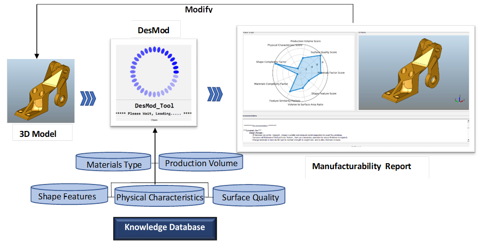
The DesMod output consists of both graphical and textual results. The graphical results include a 3D model design and a radar graph showing the scores for each of the ten factors involved in the manufacturability evaluation. The textual results are recommendations to modify the design in addition to detailed information about problematic features. DesMod provides the user with the capability to save the output report as a PDF file for later use.
2.2. Modules of DesMod tool
2.2.1. Main module
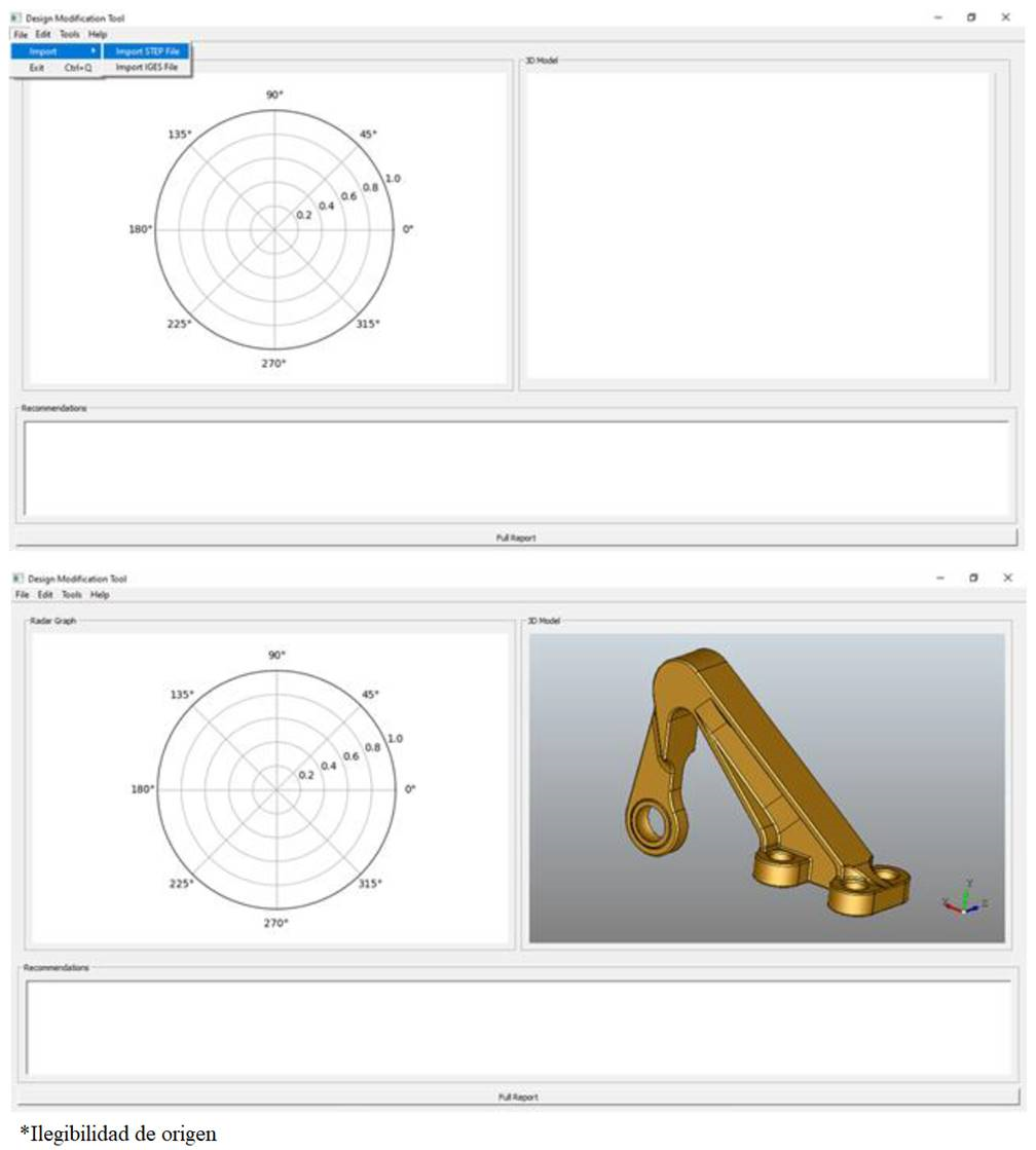
The main interface/module in DesMod includes menu bar, 3D viewer, radar graph viewer, and recommendations viewer, Figure 2 (top). Within this module, the user can import STEP or IGES files of the 3D CAD model where it will appear directly within 3D viewer, Figure 2 (bottom). The manufacturability evaluation results can also be shown within this module as a radar graph in addition to textual modification suggestions.
2.2.2. 3D Model attribute module
The model attribute module/interface consists of different databases linked to different inputs/factors within interface (Figure 3). These databases include material-process database, feature-process database, surface quality-process database, production volume-process database, thickness-process database and others.
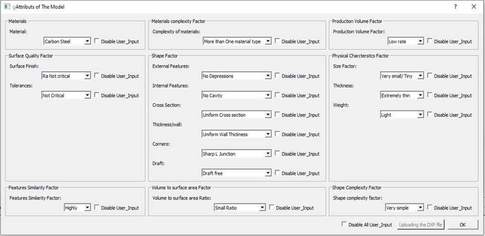
Much information related to the ten factors mentioned earlier can be entered through this module, both manually and automatically. Once information is entered in this module, either automatically through the recognition algorithm feature or manually by user, the evaluation process starts when the Ok button is clicked. The evaluation results and recommendations will appear in the main interface. The manual data input is an option within DesMod because the CAD file includes, mainly, the part’s geometric information. Other manufacturing-related information needs to be entered by the user.
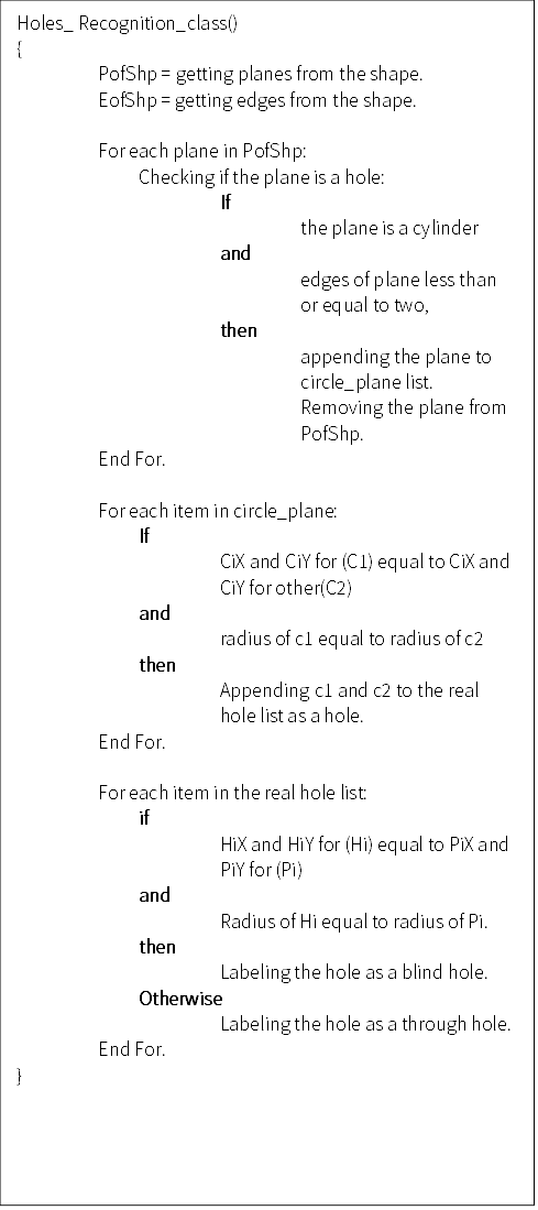
2.3. Automatic feature recognition details
As mentioned earlier, in DesMod, the features can be automatically recognized using different algorithms. An example of the pseudo code used for automatic recognition of straight cylindrical holes in DesMod is shown in Figure 4. The determination of holes in DesMod depends on extracting planes and edges from the imported 3D model STEP file. Once the planes and edges are obtained, they need to be tested against a set of conditions to check if they are forming a hole or not. For a straight hole, the center points (x, y) of circle edges, their radii at two ends, and how far each center from other edges must be equal. For through hole, the distance from each center to the part’s edges will be equal to zero, otherwise, it is a blind hole.
Similar algorithms were used to extract other features such as the square pocket, the sphere, the internal sharp corners, among other. DesMod is still under development to include more features, therefore, the manual data entry was used as an option to allow the user checking recognized features and fixing any error.
2.4. Manual features / Design information entry
The manual data input is an option within DesMod. The user can utilize this capability to check the data that is automatically filled by means of the feature recognition algorithm and to complete other information that cannot be extracted from the CAD file, if available. Information such as production volume, volume to surface area, features similarity and others.
2.5. DesMod output
The DesMod output consists of both graphical manufacturability evaluation results and textual output. Details about each type of output are discussed in the next section. The designer can view the output from DesMod in the main module or can store it as a PDF file for later use.
2.5.1. Graphical outputs
The graphical output consists of both a radar graph and a 3D CAD model. The radar graph is used to present the manufacturability evaluation results. The radar graph displays the manufacturability evaluation results of the design based on the ten factors and helps to uncover the design’s weaknesses in a way that is easy to understand and fast to read (Figure 5). Basically, the radar graph in DesMod consists of ten radii (spokes), in which each corresponds to one of the ten factors of interest. The length of the spoke/radii indicates the score of the design for that particular factor in regard to the ideal design given a certain manufacturing process. For example, a part with a material type score 7 out of 10, indicates how easy it is to process the part given the current material and a certain process used. The ends of the ten spokes are connected through a line, forming a star-like plot. This star-plot is unique in terms of providing a distinguishable feedback that sheds light and focuses attention on factors that are weakening the design and complicating its fabrication, given a particular manufacturing process.
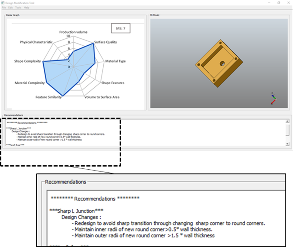
An example of the graphical manufacturability (castability) evaluation feedback from DesMod is shown in Figure 5. The feedback in Figure 5 informs the designer that the physical characteristics of the part (size, weight and thickness), and its shape features will generate a casting difficulty and that the required production volume is hard to cope with in the light of the selected manufacturing process. The reasons behind these difficulties are clarified in the recommendations window. For example, in the recommendations window, one of the suggestions is that design changes are required, basically, sharp corners have to be replaced with round ones with a guideline for the selection of fillet radii.
2.5.2. Textual output
The textual outputs of DesMod consists of design features geometric information and recommendations for design modifications.
Design features geometric information
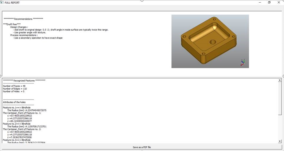
DesMod provides a summary of design features and their corresponding information. Examples of this information include the number of holes, the type of holes (blind vs. through), the diameter of the holes, the Cartesian coordinates of the hole centers, the fillets, among others. This information can be viewed in the full report window when clicking the full report button at the end of the interface (Figure 5 and Figure 6).
Design modifications suggestions
The other part of the textual output is the recommendations for the design modification. This output is simply a set of process-based recommendations to guide the designer when thinking about changes in the design. The recommendations are suggested based on all the information entered about the model. For example, if the material intended to be used is not suitable given the manufacturing process, then one of the recommendations will be to change the material or the process. If, for example, a design was planned to be casted (Figure 6) and the model does not have a draft, the recommendation will be to add a draft with the allowable range for the draft angle or change the manufacturing process per se to have the exact shape.
3. Manufacturability evaluation factors
As mentioned earlier, DesMod considers different aspects for assessing manufacturability and suggesting modifications, including material type, surface quality, features similarity, shape features, complexity of materials, volume-to-surface area, production volume, physical characteristics and shape complexity factors. A brief explanation for each of these ten factors and the basis for the scoring process used to calculate the overall manufacturability score is presented in this section. It is worth noting that, for a particular design, the scoring for each factor differs depending on the selected manufacturing process module. Beside the casting module, in DesMod, other process modules (i.e., machining and injection molding) are currently under development for which if the same part was examined using these modules, the scores will definitely differ depending on the selected module. The final version of DesMod is planned to present three different manufacturability scores in the final report: a castability score, a machinability score and an injection molding score.
The highest score among these three should give the user a hint of which process should be chosen to manufacture the part.
3.1. Material type
The materials selected for a design are crucial in determining the ease of manufacturing. Generally, some materials can be processed efficiently using some manufacturing processes which cannot be used with others. For example, carbon steel and aluminum alloys are usually preferred for parts to be sand-casted or machined whereas titanium alloys and refractory metals are less common. Furthermore, thermosets and thermoplastics are not appropriate to be sand-casted; however, they can be processed better with injection molding and rotational molding. Accordingly, the score for the part’s material in DesMod was determined given the selected manufacturing process. In other words, if the part was assessed in terms of sand casting, a score of 10 for the material will be assigned if the material was, for example, aluminum, and a score of zero will be given for thermoplastic and a recommendation will appear stating that either material needs to be changed so that the part can be sand-casted or that the process has to be changed to one suitable for polymer manufacturing.
In DesMod, the material- process matrix database was built utilizing this information, common in many textbooks (Ashby & Johnson, 2014) and then it was used to obtain the score for materials given a selected manufacturing process using a set of IF-Then rules in addition to providing appropriate recommendations.
3.2. Surface quality
The surface quality requirement is another factor that defines ease of manufacturability of a part. The surface quality factor was defined in DesMod by two attributes: surface finish and tolerances. Different surface finishes and ranges for tolerances can be obtained with different manufacturing processes. Some may provide very fine finishes and others result in rough finishes. Depending on finishing resquirement for a particular part, the score can be determined.
The overall score for the surface quality factor is the average score for both attribute scores. Each attribute can have a score of zero or 10 where if the selected process is capable of producing required surface quality, a score of 10 will be assigned, otherwise, different score will be assigned depending on level of selected process incapability of delivering required quality in addition to generating a recommendation stating that a certain secondary finishing processes are required. In DesMod, tolerance- process matrix and finishes- process matrix databases were built and then it used to obtain score given a selected manufacturing process using a set of IF-Then rules in addition to suggest appropriate recommendation.
It is worth noting that DesMod enables manual entry for surface quality information. To ensure ease of use and understanding, the ranges for finishes and tolerances were expressed verbally as well as using numerical ranges to facilitate use of this tool by novices. Finishes drop list starts with finishes (Ra) not critical (Ra>32) to brilliant polish, and tolerances drop list begins with not critical (> 2 mm) to very high precision (<=0.05 mm)(Ashby & Johnson, 2014). Once user choose an option related to tolerances or finishes, a set of If-Then rule determine score in the light of the selected manufacturing process.
3.3. Features similarity
This factor measures one aspect of the part complexity, where generally, the higher the similarity of design features, the lower its complexity and the easier its manufacturing. If features are highly similar, a score of 10 will be assigned for this factor, as the lower the similarity of feature, the lower the score. The user can visually assess the feature similarity within a design and then choose an appropriate option from the feature similarity drop list that best describes the design. Once a certain option is entered, the corresponding score will be assigned as well as any associated recommendations that can be either linked to improve features similarity or changing manufacturing process itself. As all previous factors, a set of If-Then rules are used to assign score as well as generate recommendations.
3.4. Shape factor
The shape factor evaluates the manufacturability of design with respect to its geometry. Different features/ attributes were used to define the shape factor depending on whether the assessment module is a casting or machining one. For example, six attributes including internal features, external features, cross section uniformity, wall thickness uniformity, corners type and draft were considered to be crucially affecting castability of design. Features defining shape factors were treated equally; equal importance (Boothroyd, Dewhurst, & Knight, 2010). The overall score for this factor were simply determined by averaging scores for attributes/ features that define it.
DesMod is built to extract these features automatically using algorithms such as the one described in earlier section. After extraction, fields for corresponding features/metrics will be automatically filled. More, to deal with any possible recognition issues, user is allowed to check whether features were correctly filled and fix any misrecognition if exist. As other factors, once feature is filled, the associated built in IF-Then rule will be the basis to determine the score and generate recommendations, if any. For example, if a part was planned to be casted and no draft was considered in its design then No Draft will be selected from draft attribute drop list, a score of Zero will be assigned and a recommendation will be generated stating that “a draft with certain range is suggested “and “secondary operation is needed to reach final shape”
3.5. Complexity of materials
This factor assess ease of manufacturing a part if more than one material was chosen. Simply, a score of 10 will be assigned if the part is made of one single material and a score of zero will be assigned if more than one material is chosen. When a multimaterial is used, a pop -up window will appear asking whether it is possible to make the part using one single material, if the answer is No, another question will appear, about whether the part has to be consolidated. If the answer to the second question is No, then the manufacturability evaluation module window will close, and final report generated in the main module suggesting use of additive manufacturing for producing this part.
If the part does not have to be consolidated, then a recommendation of splitting parts into pieces according to the materials chosen will be suggested.
3.6. Volume to surface area
Volume to surface area is another aspect that define ease of manufacturing in the light of the selected processes. For example, in casting, as ratio increases then the time needed to finish process increases and more mold complexity are expected to reduce likelihood of defects in casting due to shrinkage issues. In other words, as this ratio increase, the harder is to cast the part. It is worth mentioning that some people considered this ratio as metric to define the shape complexity, where the higher the ratio, the more complex the shape, hence it influences manufacturability (Boothroyd et al., 2010; Valentan, Brajlih, Drstvensek, & Balic, 2008). Accordingly, and depending on the processes, the scores for this factor are assigned between 10 to zero.
3.7. Production volume
The production volume factor was included to assess the suitability of the selected manufacturing processes for manufacturing a certain part with acceptable cost and time. For example, sand casting is suitable for production batches less than 1000 unit, unlike die casting which can produce up to 1000000 unit batch (Ashby & Johnson, 2014). The user can choose the production volume that are expected for the assessed design (i.e., small rate, medium rate, high rate) and then score can be assigned accordingly in the light of the selected manufacturing process capability of satisfying demand. To determine score for the production volume, the process- economic batch matrix was built in DesMod and used to define score. As all other factors, recommendations such as changing process will be generated depending on score for production volume factor as well as other factors scores.
3.8. Physical characteristics
This factor was defined by three main attributes: the physical size of part, its weight, and overall wall thickness. The score for the factor was determined by averaging scores for three attributes defining it. As all other factors, depending on data entering and selected process module scores, as well as appropriate recommendations ranging from modifying design to changing process are generated. The physical characteristics were chosen to be one of the factors in assessing manufacturability because they play an important role in the selection of the manufacturing process, thus, they will highly impact the manufacturability assessment score.
4. Manufacturability factors score determination in DesMod
Once all data are entered within DesMod, the manufacturability evaluation is performed and scores for factors are determined. Score for each of the ten factors is calculated by averaging the score for individual attributes used to define that factor as shown in Eq.1 below.
Where Fj is the jth factor score, wji is the importance of ith attribute used to define jth factor, Aji is the score of ith attribute used to define jth factor and nj is the number of attributes used to define jth factor. It is worth noting that the maximum score for any factor will be ten and minimum would be zero.
Aji score is determined using a set of if-then rules that map attribute to database in the background. Generally, Aij score of (10) means that ith attribute is not problematic in the light of the selected manufacturing process. For example, if aluminum alloy was the material to be used given that casting will be the manufacturing process, a score of (10) will be assigned to A11 (the material factor).
This process is repeated for each of the ten factors used to define manufacturability. Once all scores are obtained, the results will appear on the radar graph, with different radii lengths representing scores for different factors.
For example, the simple model in Figure 5 has a score of 2 for its physical characteristics’ factor, indicating that the part with its current size, thickness or weight will be hard to cast. In contrast, the surface quality factor score was 10, meaning that the surface quality requirements (i.e. tolerances and surface finish) for the model can be obtained with current manufacturing process (casting).
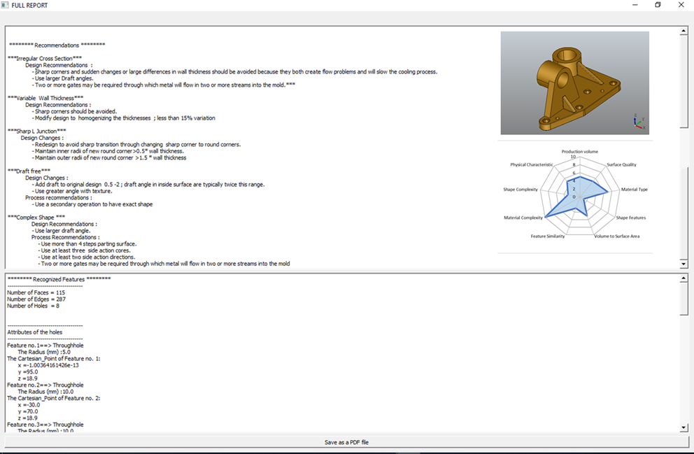
5. Tool testing
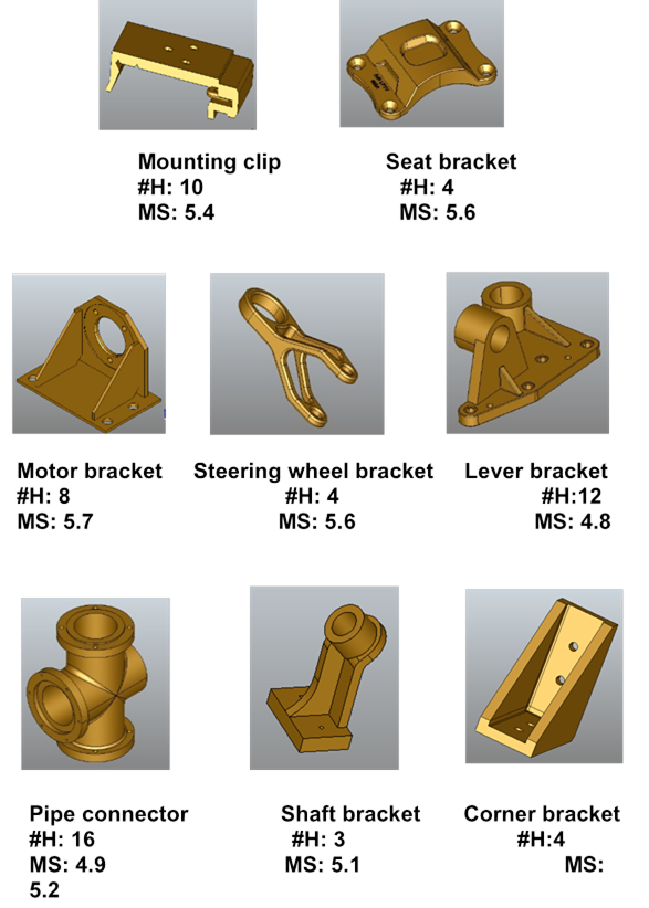
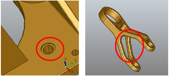
DesMod was built using Python to include assessments modules for different manufacturing processes, though casting module is the one that is tested in this paper. In DesMod, different algorithms were used to recognize features automatically/manually, to map inputs to databases, calculate manufacturability score and present recommendations. DesMod was tested using different 3D models ranging from simple shapes to complex ones and sample of results are presented in Figure 7. An example of the complete output for manufacturability evaluation (castability) for a lever bracket is shown in Figure 8. Generally, the tool was able to recognize features automatically without errors for simple to simple- moderate design but start having errors when testing complex shapes such as the steering wheel bracket and the lever bracket in Figure 8. For example, straight counter sunk holes (Figure 9a) were recognized as two holes instead of one hole. Other recognition problems were noted in parts such as in Figure 9b. However, the errors in automatic recognition were corrected through manual data entry option. Another possible solution for such problem will be to improve algorithms and use of machine learning to enhance feature recognition capability of tool.
The recommendations provided by DesMod were found to be promising in guiding the designers through the modification process. However, a more comprehensive usability study is required for further testing of the tool and proving its effectiveness to reduce the designer’s mental effort and time spent while refining their design. The current version of DesMod is limited for casting assessment, work on conventional machining assessment is in progress. To summarize, this tool can target novice designers for conceptual design editing and learning.
6. Conclusion
This paper presented a new tool called DesMod for assessing manufacturability of design as well as providing design modification suggestions feedback to aid designers. The tool provided both automatic and manual feature recognition capabilities of designs in addition to other related manufacturing related information. The designers can simply import their 3D CAD model in STEP of IGES format within DesMod. Once the model is imported, features can be recognized and mapped to the corresponding database in the background. Any additional manufacturing-related information, such as part materials, surface quality and production volume, can be manually entered. Once information about design is entered, manufacturability evaluation and associated design modification suggestion can be generated and stored in PDF format. Python and Matlab were used to build DesMod with the aim of including as many manufacturing processes as possible. However, the casting module is the one presented in this paper. DesMod was tested with many designs ranging from simple to complex and acceptable results were obtained. DesMod is still under development to include more processes and to handle more complex geometries. Moreover, possible future directions will be to utilize machine learning to enable recognition of more design features, and automatic 3D features modifications. A possible future direction is focusing on the implementation of semi-automatic design modification through an interactive gesture-based 3D viewer interface.

