


 text new page (beta)
 English (pdf)
 Article in xml format
 Article references
 Send this article by e-mail
 Cited by SciELO
  Similars in
SciELO
Similars in
SciELO 
 Permalink
Introduction
The development of glucose sensing materials came to scientific focus due to their application in biotechnology, food industry, glucose-air fuels [1], as well as clinical detections [2],[3]. Diabetes mellitus is a disease, which affects many people around the globe. As published by the World Health Organization (WHO), diabetes is the third cause of premature death on earth. In 2015 WHO reported around 415 million diabetics where the clear majority live in economically developing countries. As stated in this essay, in the year 2040, the total quantity of diabetic people will be 642 million. The principal reasons for this increment are: unbalance diet, low exercise, and sedentary lifestyle. Glucose level control is the most important tool for the people affected by this illness. Consequently, it is necessary a sensor capable of detecting the glucose concentration in the patient blood [4],[5].
Different detection methods for glucose concentrations such as spectrophotometry, thermometry, optical and electrochemical sensors have been explored [3].
Electrochemical sensors are the most used due to their simplicity, and dominate the market for glucose sensors; These can be amperometric, potentiometric or impedimetric.
In the development of electrochemical sensors on three generations can be identified; most recent based on the direct transfer of electrons [6],[7]. These sensors can be divided into enzymatic glucose and non-enzymatic glucose sensors [8]. In enzymatic glucose sensors, the glucose oxidase (GOx) is the enzyme most used [9]. However, some disadvantages of the enzyme-modified electrodes can be mentioned, for instance: electrode instability, immobilization procedure cumbersome and the enzymes are expensive and easy to lose activation [10]. Non-enzymatic glucose sensors can avoid those problems by direct catalytic oxidation of glucose on the surface of electrode. Nowadays in the literature a great variety of studies of non-enzymatic amperometric sensors are reported using materials such as TiO2-RGO [11], Ni-Cu/TiO2 [12], Zn-ZnO/TiO2 [13], TiO2-Au [14], NTs-TiO2-Ag [9], CuO [8],[10], Pt/NTs-TiO2 [15], MnCO3 [16], and others. Among of these materials, ZnO is one of the most important due to advantages as low cost, biocompatibility, and electrochemical activity [17]. Additionally, ZnO has a large family of nanostructures with different applications [18].
Many nanostructures, like nano-tubes, nano-rods, and nano-wires, have been used with the objective of carrying out the measurement of glucose concentration in a solution due to their inherently large surface area [17),(18),(19]. However, nanostructured materials have limitations such as poor adhesion to the electrode, fragility, and complicated manufacturing processes [20].
On the other hand, ZnO films exhibit properties like good sensitivity, adherence, and low toxicity. In addition, there is a wide variety of deposition methods, such as sol-gel, molecular beam epitaxy, chemical vapor deposition, and sputtering. In comparison with these techniques, the sputtering system stands out due to its low cost, simplicity and low operating temperature, as well as the quality of the resulting films [21],[22].
Few biosensors have been developed using ZnO films. For example, Saha et al. [23],[24] deposited ZnO by means of the sputtering system on ITO substrate on which he fixed GOx to detect glucose concentrations, an increment in the sensitivity from 1.02 to 1.27 μAcm-2mM-1 of the biosensor is reported when the working pressure increases from 20 to 50 mTorr; in the other hand they reported that the electrodes based on ZnO thin films, which are under the influence of higher stress, show better sensitivity. However, these biosensors are dependent on the use of an enzyme. Hence, it is necessary to develop studies in order to that the ZnO thin film be used in as non-enzymatic (NEG) glucose sensor.
In this work, we propose the application of ZnO films for the development of a NEG sensor, using titanium as a substrate since it has a metal work function that the junction between these materials forms an ohmic contact, which easily allows that the charge flow from the semiconductor to the metal [25].
Experimental details
Titanium sheet (98.50%), D-(+)-glucose, and NaOH were purchased from Sigma-Aldrich; ZnO target (99.999%) with a diameter of 2.00", and 0.125" thick was bought from Kurt J. Lesker. ZnO films were deposited on titanium (Ti) and glass substrates, at room temperature, by pulsed-DC magnetron sputtering in argon gas atmosphere at a power of 100 W. The target-substrate distance was set at 36 mm on axis without substrate rotation. In order to investigate the influence of the thickness on the performance of the glucose sensor, the deposition time was varied at the values of 15, 20, and 60 min.
The samples grown on glass substrates, were characterized by optical transmission by an Ocean optics spectrophotometer model USB4000-XR1-ES coupled to UV/Vis/NIR light source model DH-2000. Morphologies of the sputtered films were observed with a scanning electron microscope (JSM-6390LV). The X-Ray Diffraction (XRD) patterns were collected with an X-ray diffractometer using the CuKa radiation (D8 ECO, Bruker). The electrochemical measurements were made using a Princeton Applied Research potentiostat, model VersaSTAT3.The used electrochemical cell had a configuration of three standard electrodes: a silver-silver chloride (Ag-AgCl) as reference electrode, a platinum counting electrode (mesh of 1cm2 area) and a working electrode (ZnO/Ti thin film). For cyclic voltammetry and chronoamperometry, NaOH 0.1 M solution (pH 13) was used as electrolyte and different concentrations of glucose (150 mg/dL to 300 mg/dL) were prepared. The parameters used to perform the cyclic voltammetry were voltage sweep loop from -1.0 V to 1.0 V and back to -1.0 mV with sweeping speed of 50 m V / s. The chronoamperometry was made remaining fixed the voltage at 0.9 V, with respect the reference electrode.
Results and discussion
Figure 1 shows the optical transmittance spectra of the three samples grown on glass substrates. It could be observed that the oscillations increase with the deposition time, suggesting that the thickness increases in the same manner. With the purpose of obtain the value of the thickness of each sample, it was modeled the optical transmission spectra by using the SCOUT software. The thickness obtained were 705.2 nm, 945.3 nm and 2531.7 nm for the samples of 15 minutes, 20 minutes and 60 minutes, respectively. The bandgap of each sample was calculated using the Tauc method for optical absorption edge; the values obtained were 3.28, 3.27 and 3.18 for the samples of 15 minutes, 20 minutes and 60 minutes, respectively. The differences between the values could be due that the fact the samples were grown without substrate temperature, and that we used glass slides for the optical measurements; the glass substrate is amorphous, and when we deposit the ZnO film, the interface has a high number of dislocations; so at the beginning the film has amorphous characteristics. When the thickness increases, the ZnO film becomes crystalline, then the different values could be due at the difference in crystallinity of the films.
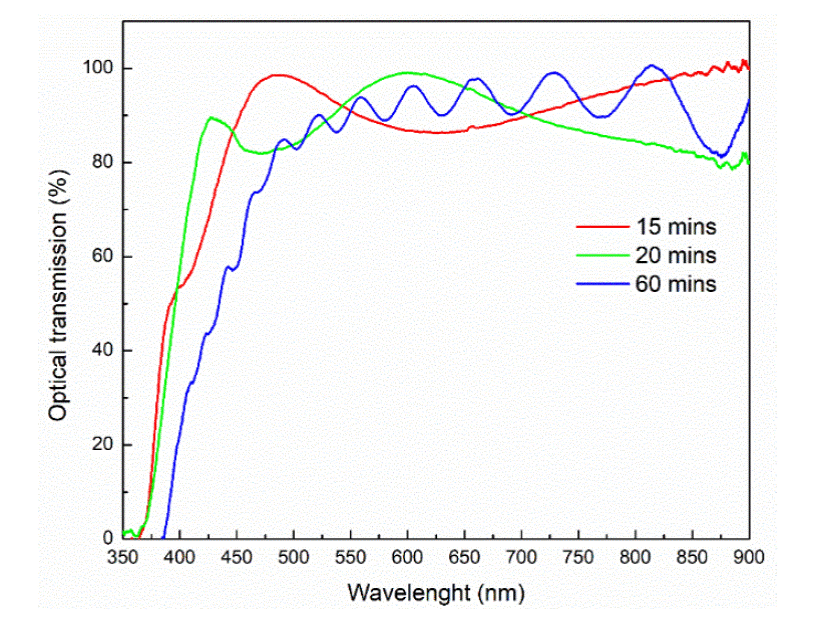
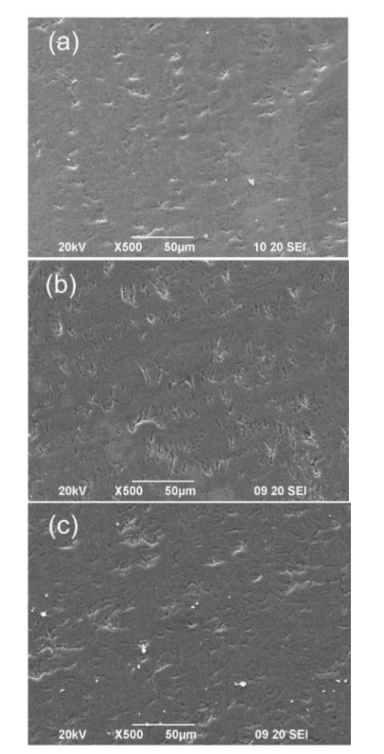
Figure 2 shows the SEM images of the ZnO/Ti films deposited at 15, 20 and 60 minutes. The samples have a morphology without protrusions and ridged with slits over its entire surface. At the scale that the SEM allows us to observe that the deposition time does not noticeably affect the morphology of the films since the density of the slits in the four samples is very similar. The cracks could be due to mechanical stress between the growing film and the titanium substrate, due to the decoupling between the crystalline structures of both materials.
The x-ray diffraction pattern of the sample grown on glass substrate at deposition time of 60 minutes is shown in figure 3. The diffraction peaks were indexed using the JCPDF card number 361451. All crystallographic planes corresponded to hexagonal phase of the ZnO. The samples grown with deposition time of 15 minutes and 20 minutes had peaks with less intensity that the sample with deposition time of 60 min;these results are consistent with the obtained in the optical transmission measurements.
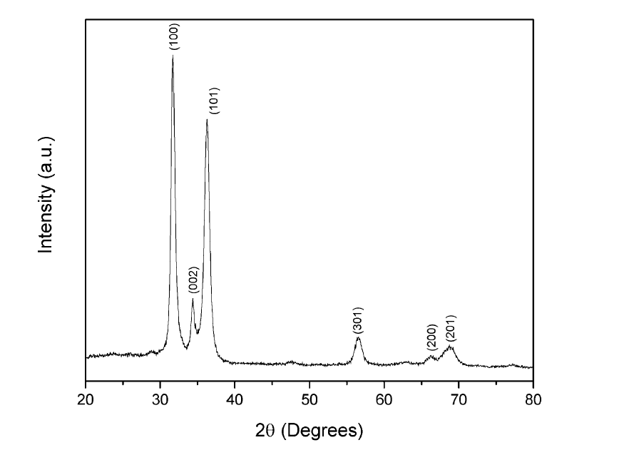
Figure 4. (a) shows the cyclic voltammograms (CV) of the ZnO/Ti electrode deposited at 60 minutes, varying the glucose concentration from 150 mg/dL to 300 mg/dL with an increase of 50 mg/dL. The inset shows an approach in the potential range of 0.7 to 1.0 volts where the four curves look very similar despite the changes in concentration. In the potential of 0.90 V vs Ag/AgCl, there is no tendency of growth in the current response when increasing the concentration of glucose in the solution, which indicates that its behavior is erratic. We obtained similar results with the sample grown at 20 minutes of deposition time.
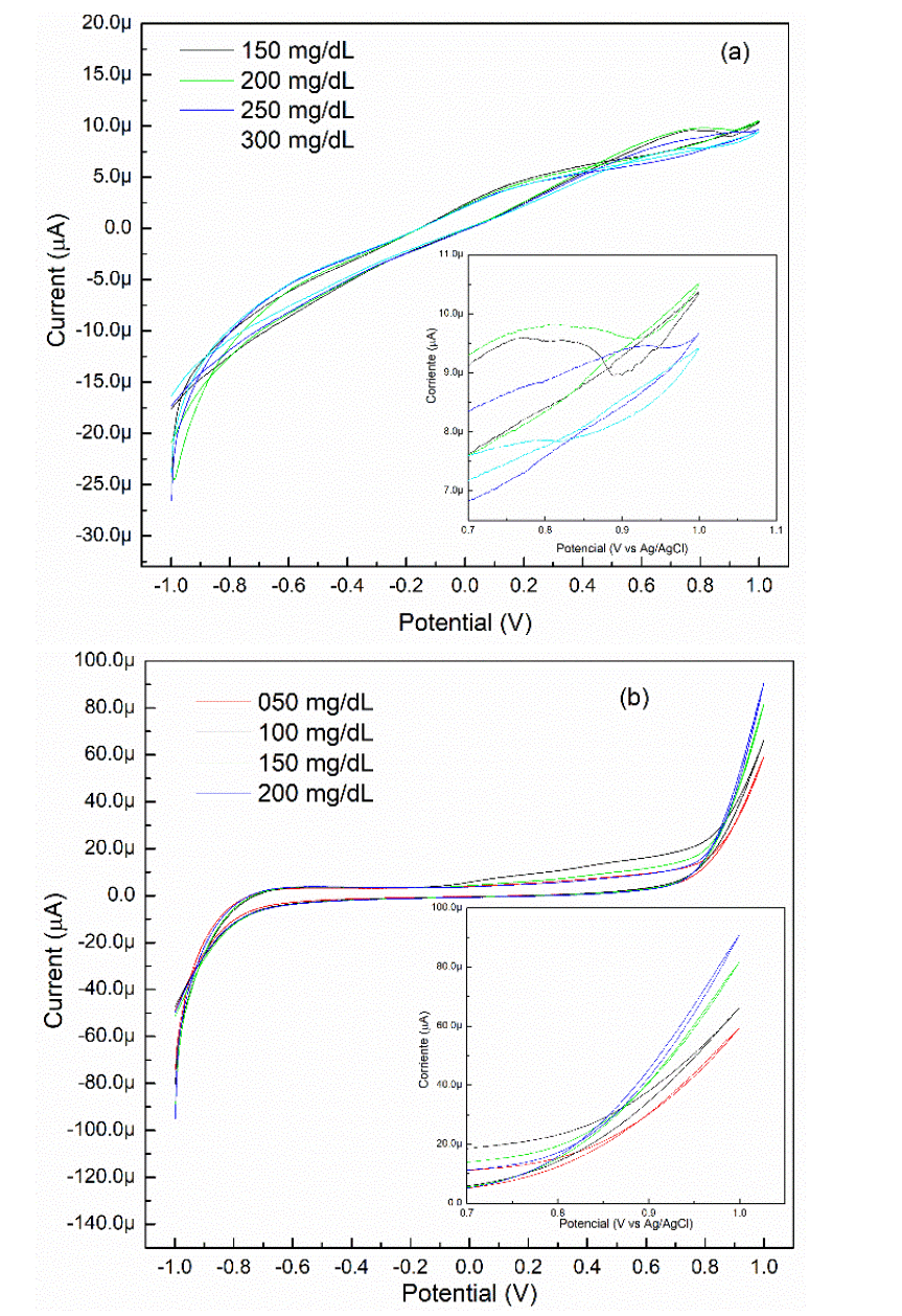
Figure 4 CV of the ZnO/Ti electrode deposited at (a) 60 minutes and (b) 15 minutes in 0.1 M NaOH solution at different glucose concentrations. The inset shows the oxidation region of glucose.
On the other hand, figure 4 (b) shows the CV of the ZnO/Ti electrode deposited at 15 minutes. The inset shows a clear current increment in the potential range of 0.8 to 1.0 volts vs Ag/AgCl by raising the concentrations of glucose in the solution. For this case, it is observed that the current response is greater than the ZnO/Ti electrode deposited at 60 min. The applied potential (0.90 volts vs Ag/AgCl) favored creating an anodic current in the semiconductor-electrolyte interface. The oxidation current flows through the working electrode, then the electrons are transported across the ZnO layer to the titanium substrate. When the thickness increased, the electrons have more possibility of get trapped in the defects of the film. Hence, due that the ZnO/Ti electrode deposited at 15 minutes showed an increase in the current response in relation to changes in glucose concentration in the solution, it was determined to continue with the characterization of this sample to obtain sensitivity and linearity of the biosensor.
The chronoamperometric curves presented in figure 5 shows the relationship between current and time when changing analyte concentrations. By varying the glucose concentration, the current response increases in the same way, stabilizing after ten seconds of having applied the potential to the cell. The amplitude of the current-time curve reflects the change in analyte concentration at the electrode surface. This involves a decrease in the current response as time elapses due to the exhaustion of glucose.
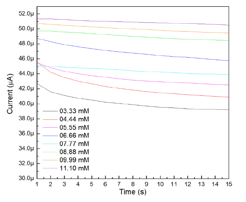
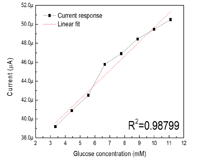
In order to calculate the sensitivity and linearity of the biosensor based on ZnO and titanium, the current response curve was constructed at 0.90 volts vs Ag/AgCl vs the concentration of glucose in the range of 3.33 to 11.10 mM. According to the constructed calibration curve of the ZnO/Ti electrode deposited at 15 minutes is shown in figure 6, the slope of the line is 1.5 μAmM-1. To obtain the sensitivity of the built biosensor, the slope is divided between the area of the electrode in contact with the solution, which was 0.196 cm2 [26]. As a result, the sensitivity of the developed biosensor was 7.65 μAcm-2mM-1 with a correlation coefficient (R2) of 0.98799 [27]. The non-enzymatic glucose biosensor has a linearity range of 3.33 to 11.10 mM and the current response responds to the linear equation:
Conclusions
We fabricated a NEG sensor based on ZnO films deposited by the sputtering technique on titanium substrates. The fabricated sensor yielded a maximum sensitivity of up to 7.65 μAcm-2mM-1 with linearity within the range of glucose concentration that usually occurs from a healthy person to a diabetic person. Therefore, the potential application of the system is evident. The SEM images show that the deposition time did not affect the morphology of the samples grown on titanium since the surface of the films obtained is very similar. Finally, the electrochemical characterization shows that by applying a potential of 0.90 volts vs Ag/AgCl to samples with different thicknesses, the flow of an anodic current in the semiconductor-electrolyte interface is favored. However, the current response of the electrode is affected by the thickness of the sample, since the electron transfer increased by reducing the thickness of the ZnO film.

