


 text new page (beta)
 English (pdf)
 Article in xml format
 Article references
 Send this article by e-mail
 Cited by SciELO
  Similars in
SciELO
Similars in
SciELO 
 Permalink
Introduction
Currently, the conversion of electrical energy is of the utmost importance due to the great variety of existing burdens, which have different requirements to perform a specific task. This paper focuses on the conversion of energy from direct current (DC) to alternating current (AC), which is carried out by devices called inverters.
According to the number of levels of the output voltage, the topologies of the inverters are classified in conventional or multilevel (Franquelo et al., 2008; Jih & Fang, 1996; Tolbert et al., 1999). The basic structure of conventional inverters consists of power switches which, by means of a suitable switching sequence, provide a symmetrical alternating voltage containing two voltage levels from a direct current voltage (Coronel, 2016). On the basis of the previous structure, the multilevel topology arises, which has been consolidated in recent years as a competitive option for the conversion of energy in the medium-high power range, both from a technical and economic point of view (Mittal et al., 2012).
The main function of the multilevel inverters is to synthesize the desired output voltage from several levels of direct current input, using a wide variety of modulation techniques for energy conversion.
Compared to conventional inverters, multilevel inverters present the following advantages:
Reduction in switching losses.
Stress reduction in power semiconductor devices.
Improvement in the output waveform.
Decrease in the Total Harmonic Distortion (THD) and the Weighted Total Harmonic Distortion (WTHD).
Multilevel inverters are classified mainly in three topologies: Flying Capacitor Multilevel Inverter (FCMLI), Diode Clamped Multilevel Inverter (DCMLI) and Cascade Multilevel Inverter (CMLI) (Nami et al., 2008; Rani et al., 2014). This paper focuses on the cascade multilevel topology, which is briefly described in the following section.
Nowadays, inverters are considered the most widely used power converters in industry (Gonzalez et al., 2016). For this reason, the study of inverter behaviour under different operating conditions and applications is of great importance. The main inverters applications in industrial processes are the induction motors. Therefore, is necessary to ensure the suitable performance of the motor-inverter assembly.
The motor-inverter assembly presents some inherent phenomena, which directly influence the useful life of the engine; one of these phenomena is related to the THD value of the inverter output waveform. This directly influences the behaviour of the operating conditions of the motor, such as (Franquelo et al., 2008, Méndez, 2011):
Motor temperature increase.
Stator coils damage, due to high voltage pulses.
Increase in motor noise level.
Vibration increase.
Therefore, there is a growing interest in the design of inverters with high performance, capable of reducing stress in power semiconductor devices, reducing the THD value and highly efficient in the conversion process, to meet the requirements of their applications and ensuring a reliable performance and, contributing to prevent economic losses to the industry (Gonzalez et al., 2016; Rashid, 2004; Tolbert et al., 1999).
The importance of analyzing the behavior of two main concepts involved in the DC-AC energy conversion process is emphasized: the inverter topology and the switching sequence, without leaving aside its influence on the system load. Therefore, it is convenient to observe the behavior of parameters that influence the evaluation of the performance of the system load, in this case, the induction motor. To summarize, Table 1 contains the main parameters used in the evaluation of the performance of the inverter-load assembly of the system.
Table 1 Main parameters used to evaluate the performance of the inverter-induction motor assembly
| Inverter | Unit | Induction motor | Unit |
|---|---|---|---|
| THD | % | Temperature | °C |
| WTHD | % | Nominal Speed | rpm |
| Output voltaje Amplitude | V | Pair | N⋅m |
| Vibration level | m/s2 | ||
| Noise level | dB | ||
| Efficiency | (%) |
Therefore, a review of several papers analyzing the behaviour of the cascade multilevel inverter with different modulation techniques was carried out. However, most of these papers are focused only on the results of THD, WTHD, and phase balancing in the case of three-phase systems, without taking into account the behaviour of load parameters (Franquelo et al., 2008, Hosseini et al., 2009; Kumar & Narayanan, 2016; Peng et al., 1997; Tolbert et al., 2003).
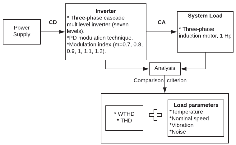
In this paper, a comparison of the Phase Disposition Pulse Width Modulation (PD-PWM) strategy was made with different modulation indexes used in a three-phase cascade multilevel inverter (seven-levels) with a three-phase induction motor as load. The aim was to observe the behaviour of parameters related to the inverter output waveform, such as THD and weighted total harmonic distortion (WTHD) values, as well as parameters related to the induction motor, such as noise, vibration, nominal speed, and temperature. A diagram of the above is shown in Figure 1.
Performance parameters in multilevel converter
As mentioned in the previous section, for the case study established in this paper, it is required a trade-off between two concepts involved in the energy conversion process, which are: inverter topology and switching sequence. These concepts are briefly described below:
a) Inverter topology
The topology selected as the case study is a three-phase cascade multilevel inverter (seven-levels), the schematic diagram is shown in Figure 2. This topology is based on the cascade connection of full bridges, also called cells, with isolated DC voltage sources; each cell provides two voltage levels, and the number of levels generated in the output voltage depends on the number of cells.
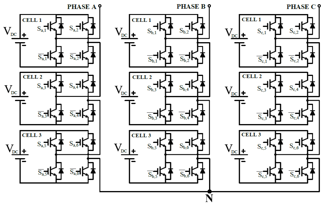
In the symmetrical cascade multilevel inverter, the voltage source levels of each of its cells, has equal magnitude; each cell provides two voltage levels, and the number of levels (n) generated in the output voltage depends on the number of cells (z) and are expressed mathematically below:
Where:
The CMLI topology has the following main advantages compared to the other multilevel topologies (Alepuz, 2004; Franquelo et al., 2008; Venkataramanaiah et al., 2017):
Modular construction.
Reduced number of components to obtain the same number of levels.
Power semiconductor devices support only the voltage present in a direct current source.
b) Switching sequence
The optimal performance of an inverter depends mainly on the modulation technique employed. The modulation strategy used in this paper is the PD-PWM, which is based on the comparison of carrier signals with the same amplitude and phase, with respect to reference signals.
The number of carriers needed to generate an output signal with the required number of levels can be calculated with:
Where:
Figure 3 shows the six carrier signals and the three modulating signals for a three-phase system, when compared, generate a seven-level output waveform.
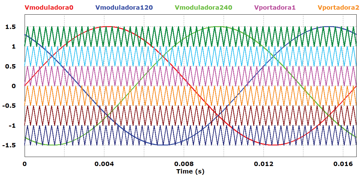
The modulating signals vary depending on the modulation index required, which is calculated by (3). When the modulation rate is greater than 1, then there is overmodulation.
Where:
The output signals from this comparison (see Figure 4), are used to generate the switching states of the switches corresponding to the topology of study.
Experimental results
The experimental tests carried out on the motor-multilevel inverter assembly were carried out using the specified topology and modulation technique, based on the general electrical scheme presented in Figure 5, varying only the modulation index.
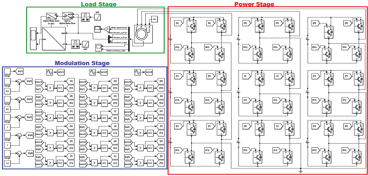
In the modulation stage is the generation of the carrier and modulator signals, as well as the comparisons of the same, which result in the switching states that activate/deactivate the circuit breakers that integrate the topology of three-phase cascade multilevel inverter of the power stage. The C.A. voltage signal resulting from the switching of the power circuit breakers is used to drive the induction motor belonging to the load stage.
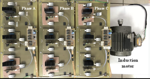
The experimental tests were carried out with the specifications and laboratory conditions shown in Table 2. As well as using the test bench shown in Figure 6.
Table 2 Experimental test specifications
| Specifications | Value |
| Test duration | 60 min |
| Number of measurements per test | 60 |
| Ambient temperature | 29°C(±5%) |
| Ambient humidity | 32%(±1%) |
| Switching frequency | 3.3 kHz |
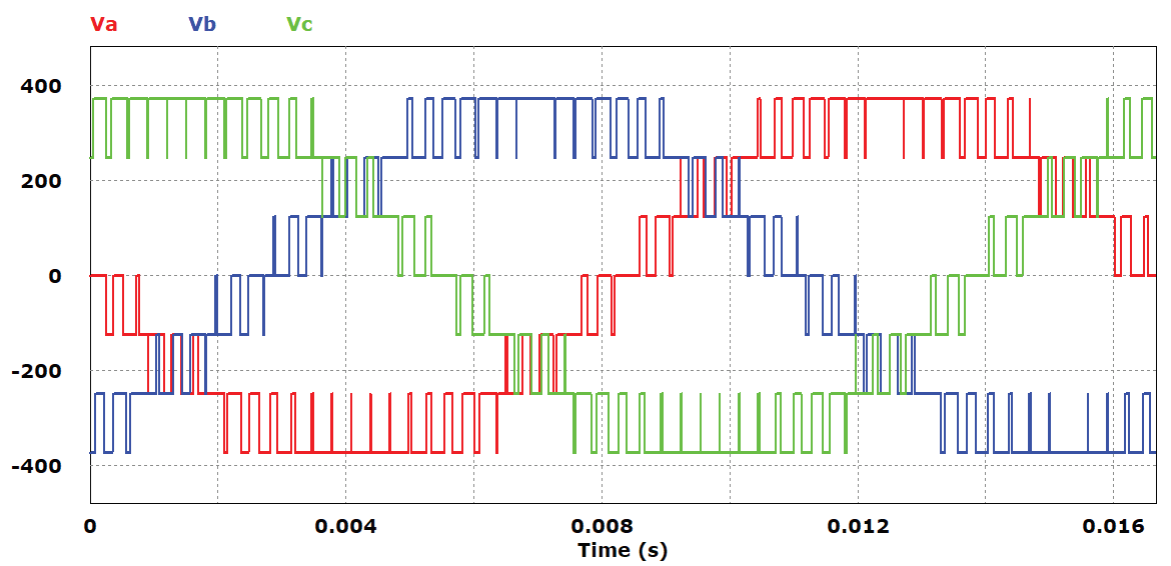
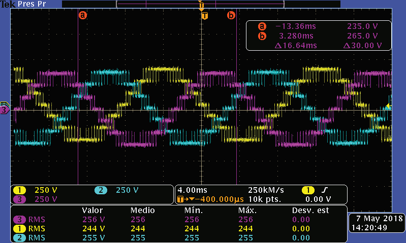
The tests were performed in compliance with the specifications shown in Table 2, the modulation index for the PD-PWM strategy was selected. For each modulation index the three-phase voltage signal was obtained at the output of the inverter, resulting from the switching action of the power switches (Figure 7).
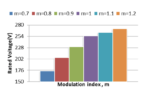
Once the modulation index was selected, measurements of the study parameters were carried out for the duration of the test. Firstly, the graphs of the cascading output signal of the cascade multilevel inverter are presented only from phase A because the behaviour of the other two phases (B and C) is similar to this one. Figure 8 shows the line voltage variation with the different modulation indexes selected for the experimental tests. As can be observed, the higher the modulation index, the line voltage increases; this is because the amplitude of the sine wave increases and there is a larger cut-off area between it and the carrier signal, which leads to a larger energy transfer area.
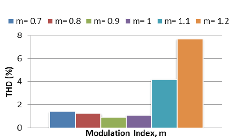
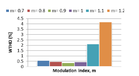
The THD and WTHD variations of phase A output voltage are shown in Figure 9 and Figure 10, respectively. It can be observed that both values increase considerably when the modulation index is higher than the unit, i.e. overmodulation, which leads to the absence of pulses from the upper and lower part of the output voltage signal. Furthermore, there is a tendency to increase the value of these parameters when the modulation index approaches the allowed limit at which seven levels are obtained.
The results obtained from three-phase induction motor during the test time are presented below, considering: noise, vibrations, and temperature. Figure 11 shows the noise levels obtained and shows that the modulation index 0.7 showed a lower noise level. In contrast, the modulation rate with high noise results is 1.2. This is a consequence of the fact that by increasing the modulation index, the voltage and current stresses increase.
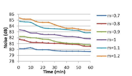
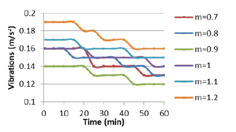
Figure 12 shows the results obtained from the vibration over the test time and shows that when there is overmodulation the vibrations increase. Likewise, when the modulation index approaches the allowed limit at which the seven levels are obtained. It can be observed that the modulation index with the lowest vibration is 0.9. In addition, the lowest THD and WTHD values were obtained with this modulation index.
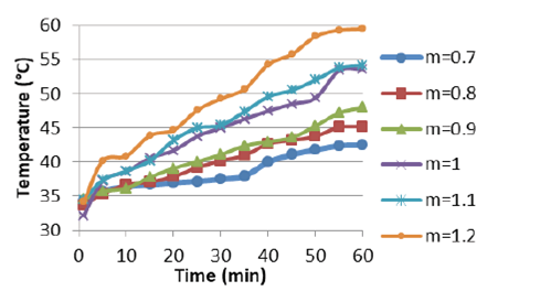
The behaviour of temperature vs. modulation index is shown in Figure 13, with an ascending trend with respect to time and modulation index. The higher the modulation index, increase the operating power.
Results discussion
Taking into account the results obtained from the experimental tests, a summary is presented in Table 3. The behaviour of the different modulation indexes in relation to the measurement parameters that influence the performance of the motor-inverter assembly is shown, identifying with an “x” the modulation index with the most favourable result in each parameter.
Table 3 Experimental test specifications
| Measurement parameter | Modulation index | |||||
|---|---|---|---|---|---|---|
| 0.7 | 0.8 | 0.9 | 1.0 | 1.1 | 1.2 | |
| THD | X | |||||
| WTHD | X | |||||
| Noise | X | |||||
| Vibrations | X | |||||
| Temperature | X | |||||
Table 4 shows the comparison of the results between the nominal values and the values obtained with a modulation index m = 0.9.
Table 4 Comparison of selected modulation index vs. nominal motor parameters
| Measurement parameter | Nominal values | Values obtained with m = 0.9 | Variation with respect to the nominal value |
|---|---|---|---|
| Noise | 82.06 dB | 82.21 dB | 0.18 % |
| Vibrations | 0.10 m/s2 | 0.12 m/s2 | 20 % |
| Speed | 1796 rpm | 1796 rpm | 0 % |
| Temperature | 49.3 °C | 48 °C | 2.63 % |
Conclusions
The paper presents a comparison of the Phase Disposition Pulse Width Modulation (PD-PWM) strategy performed with different modulation index used in a three-phase cascade multilevel inverter (seven-levels) with a three-phase induction motor as load.
A comparative analysis was performed of the behavior of parameters related to the inverter output wave-form, such as THD and weighted total harmonic distortion (WTHD) values, as well as parameters related to the induction motor, such as noise, vibration, nominal speed and temperature vs. the modulation index.
From the comparative analysis, it can be concluded that the modulation index m = 0.9 showed better results in most of the study parameters. In contrast, the modulation index m = 1.2 (i.e. overmodulation) presented the most unfavorable results. This is important because selecting the appropriate modulation index represents better results in the performance of the motor-multilevel inverter assembly, helping to reduce heating, vibration, and noise in the motor, which can cause failures, decrease its reliability and useful life.

