


Services on Demand
Journal
Article
 English (pdf)
 Article in xml format
 Article references
 Send this article by e-mail
Indicators
-
 Cited by SciELO
 -
 Access statistics
Related links
-
 Similars in
SciELO
Similars in
SciELO
Share

 Permalink
Ingeniería, investigación y tecnología
On-line version ISSN 2594-0732Print version ISSN 1405-7743
Ing. invest. y tecnol. vol.14 n.4 Ciudad de México Oct./Dec. 2013
Analysis of Flow and Heat Transfer in a Flat Solar Collector with Rectangular and Cylindrical Geometry Using CFD
Análisis de flujo y de la transferencia de calor en un colector solar plano con geometría rectangular y cilíndrica utilizando CFD
Marroquín-De Jesús Ángel1, Olivares-Ramírez Juan Manuel2, Jiménez-Sandoval Omar3, Zamora-Antuñano Marco Antonio4 y Encinas-Oropesa Armando5
1 Universidad Tecnológica de San Juan del Río, Querétaro. E-mail: amarroquind@utsjr.edu.mx
2 Universidad Tecnológica de San Juan del Río, Querétaro. E-mail: jmolivar01@yahoo.com
3 Centro de Investigación y de Estudios Avanzados (CINVESTAV) Instituto Politécnico Nacional, Unidad Querétaro. E-mail: ojimenez@qro.cinvestav.mx
4 Universidad Tecnológica de San Juan del Río, Querétaro. E-mail: mazamoraa@utsjr.edu.mx
5 Universidad Autónoma de San Luis Potosí. E-mail:armando.encinas@gmail.com
Information on the article: received: June 2012.
Accepted: November 2012
Abstract
The present investigation describes the construction and experimentation of two solar energy absorbersusing water as working fluid and its simulation in Computational Fluid Dynamics (CFD). For Absorber A with rectangular cross section and Absorber B with circular cross section, water temperature was calculated using solar radiation and ambient temperature measurements showing increases of up to 62.5°C for both absorbers. The maximum thermosiphonic flow measurement in Absorber A was 70 l/h and 79 l/h in Absorber B. On this basis, finite element method and CFD were used to analyze the difference between both flows, with 45, 50, 55, 60, 65 and 70 l/h as simulation values. With the simulation results the Reynolds numbers were determined, finding that the maximum flow (70 l/h) gives the largest Reynolds number variation: 25 ≤ Re ≤ 115 for Absorber A and 199 ≤ Re ≤ 235 for Absorber B. With a smaller variation in Absorber B, the flow at all ducts turns out to be more uniform, which results in more ducts transferring heat to the working fluid.
Keywords: flow structure, flat solar collectors, simulation cfd, heat transfer, solar radiation.
Resumen
La presente investigación describe la construcción y la experimentación de dos absorbedores de energía solar que utilizan agua como fluido de trabajo y su simulación en dinámica de fluidos computacional (CFD). Para el absorbedor A con sección transversal rectangular y el absorbedor B con sección transversal circular, la temperatura del agua se calculó utilizando la radiación solar y las mediciones de temperatura ambiente muestran incrementos de hasta 62.5°C para ambos absorbedores. La medición del flujo termosifónico máximo en el absorbedor A fue de 70 l/h y en el absorbedor B de 79 l/h. Sobre esta base, el método de elemento finito y CFD se utiliza para analizar la diferencia entre ambos flujos, con 45, 50, 55, 60, 65 y 70 l/h como valores de simulación. Con los resultados de la simulación se determinaron los números de Reynolds, encontrándose que el caudal máximo (70 l/h) ofrece la mayor variación del número de Reynolds: 25 ≤ Re ≤ 115 para el absorbedor A y 199 ≤ Re ≤ 235 para el absorbedor B. Con una variación menor en el absorbedor B, el flujo en todos los conductos resulta ser más uniforme, lo que implica más conductos transfiriendo calor al fluido de trabajo.
Descriptores: flujo estructural, colector solar plano, simulación en CFD, transferencia de calor, radiación solar.
Introduction
Solar energy collection as a topic of renewable energy has been the primary interest of many researchers for the past two centuries, because it can reduce the cost of domestic water heating up to 70%. More attention was paid to this topic in the early 70s due to the global oil crisis of 1973 (Selmi et al., 2008), increasing the need for better heat absorption-performance in the equipment. In the design and configuration of solar heating systems, Naewngerndee et al. (2011) has developed a research on flows with cylindrical geometry, evaluating the performance when these flows are placed in long, square and wide array modules, resulting in an optimization of the flow from 1 l/min to 3 l/min when squarearray modules are used. Design and validation were done using the finite element method which was solved with CFD. Moreover Zhu et al. (2011) evaluated the amount of heat that acts on a surface when the fluid velocity varies, validating the simulation results by CFD. Kumar and Saini (2008) built a solar air heater and used CDF to evaluate the heat transfer effect on a bow-shaped geometry working with the Reynolds number and the k-ε model used on this investigation.
Grossman and Zvirin (1977) conducted experiments in a parallel-plate absorber which would be very similar to one single channel of Absorber A in this study. Evaluating the separation between the plates to determine their efficiency, Grossman concluded that reducing the separation increases the efficiency. However, reducing the separation between the plates also decreases the flow rates. This type of geometry provides high contact area between the fluid and the absorber surface exposed to solar radiation.
The main objective of this research is to evaluate the performance of two types of absorbers: One with pipes and the other with rectangular ducts, through the construction, experimentation, theoretical formulation and its simulation of flow and heat transfer.
Experimental
Construction of prototype
The solar heater housing (Figure 1) with dimensions 0.095 m high, 1.00 m wide and 1.60 m long was built with C-150 steel profile (frame) and 22 gauge galvanized steel sheet. The joints were sealed with silicone to prevent air leakage and the inner part was covered with a 0.02 m-thick polystyrene plate. Absorber A was built of one "Zintro" channel-shaped steel plate (0.01 m high, 0.89 m wide and 1.47 m long) welded to a flat 22 gauge galvanized steel sheet, forming 10 rectangular cross section channels (0.01 m high, 0.08 m wide and 1.47 m long) separated 0.01 m from each other. The formed channels were welded to two heads of galvanized pipe (0.0381 m diameter and 1.10 m long) and the entire absorber painted with fast dry black paint. Absorber B was built with nine copper pipes (0.0127 m diameter and 1.47 m long) separated 0.09 m from each other and welded to two heads of copper pipe (0.0381 m diameter and 1.10 m long). Like Absorber A, the whole absorber was painted with fast dry black paint. The cover is a flat rectangular window-glass 0.004 m thick, 1.00 m wide and 1.60 m long. The water tank is formed by two concentric cylinders. The diameters are 0.52 m for the inner cylinder and 0.72 m for the outer one and the lengths 0.72 m and 0.92 m, respectively. The space between the two cylinders was filled with polyurethane foam.
Modeling "Ansys Workbench" - the preprocess
The domain geometry of the fluid was prepared using "Design Modeler". Physics Preference, CFD, Mesh Method and CFX-Mesh were considered for the meshing. The face spacing settings for Absorber A were the following: edge length between 0.004 m and 0.08 m; The angular resolution for the top and bottom surfaces was set to 30°; the angular resolution for the lateral surfaces of the channel was set to 18°; the edge length for the head pipes was set to 0.005 m with a maximum thickness inflation of 0.08 m. The face spacing settings for Absorber B were the following: for the 0.0127 m diameter pipe, the edge length was set between 0.005 m and 0.025 m, with 30° in the angular resolution; for the head pipes the edge length was set between 0.005 m and 0.008 m and the maximum thickness inflation was set to 0.025 m, generating the mesh shown in Figure 2.
System equations
Heat transfer
As shown in Figure 3 considering that there is no absorption of solar energy in the glass, the radiosity for the absorber is: J1 = Eb1 and the energy supplied to surface 1 is

Considering the radiant exchange

The global energy balance of surface 2 is
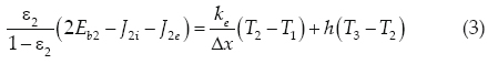
For the global system, the absorbed solar energy must in the end be transferred to the exterior of the glass by convection and radiation
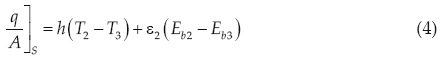
The lost radiation through the outer surface of the glass is

The heat exchange from the absorber to the working fluid

Finally obtaining T0 , which is the temperature of the working fluid (Holman, 2001)
Fluid mechanics
The independent parameters included are the Reynolds number and the geometry of each Absorber. The Reynolds number is based on the hydraulic diameter:
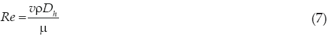
For the geometry of Absorber A 4WH

For the geometry of Absorber B, Dh is the diameter of the 0.0127 m diameter pipe (Elshafei et al., 2010).
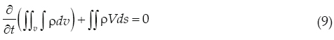
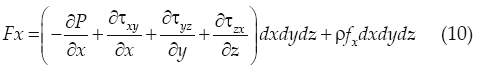
The fluid interaction with its surroundings can be calculated using computational tools when it requires thousands of calculations. In these complex situations it is almost impossible to manually do the calculations. The computational tools calculate fluid properties point by point for each process and the mathematical fluid relations are often solved numerically with a computer. The physical aspects of any fluid flow are governed by three fundamental principles: The continuity equation:
Newton's Second Law of Motion:
and energy conservation.
The CFD software tool can replace integrals and partial derivatives with discretized algebraic forms, which at the same time are solved to obtain the field parameters of the flow in discrete points, time and space (Karmare and Tikekar, 2010).
Test conditions
Prototype data
The experimentation was developed during May 2010, in the city of San Juan del Río, state of Querétaro, México; it is located 20° 23'N, 99° 59' W, with high solar radiation levels during the year. The collectors were side by side with an inclination angle equal to the place latitude for both collectors. Between the thermo tank and the solar collectors there was a vertical distance of 0.25 m to prevent the return of water overnight according to Rudnick et al. (1986).
Solar radiation was measured with an Eppleypyrheliometer model NIP, capable of measuring a range of from 0 to 1400 Wm-2, mounted on a solar tracker ST-1. The ambient temperature was logged with a DB-535 data collector. With the radiation and ambient temperature data, the heat transfer model was solved to determine the working fluid temperature. The results are shown in Figure 4.
Water temperature was measured at the zenith time, with a data collector DB-535 equipped with an RS-232 communication port, programmable sampling rate and data DB-Lab processing system. Measurements were obtained along the channels, where point 1 was located near the head inlet and point 7 near the head outlet, the rest of the points were distributed evenly throughout each channel or pipe (depending on the absorber). Figure 5 shows the typical temperatures reached on channels 1, 6, and 10 of Absorber A and pipes 1, 6, and 9 of Absorber B.
A Blue-White® flow meter, with measurement range from 0.4 to 4.0 l/min, was connected in series between the collector and the thermo tank. The temperature of the water contained in the thermo tank was measured with a data collector DB-535. The results are shown in Figure 6.
Analysis in CFD
Flow analysis was developed in CFD considering: The general domain as water, a Thermal Energy process, the k-ε model, a 800 W/m2 heat flow on the wall, a 12.17 x 10⁻³ m/s entry flow velocity, a 293 K temperature and a 0.00 Pa outlet relative pressure. The results are shown in Figure 7.
Results and discussion
Thermal profile
With the solar radiation and ambient temperature data applied to the theoretical heat transfer model the water temperature is obtained. The results are shown in Figure 4. These calculated results are consistent with the experimental data shown in Figure 5. The water temperature is similar in both absorbers according to the theoretical (Figure 4) and experimental (Figure 5) results. An 8 K variation is noticed in the experimental results when measuring the temperature between the inlet and outlet water for both absorbers. The maximum variation between ducts is 3.4 K for both absorbers. Considering this low temperature increases according to the thermal testing there should be a similar thermosiphonic effect for all ducts. However, the flow measurement values (Figure 6) show different results: There is a bigger area under the flow curve for Absorber B, getting higher temperature of the water contained in the thermo tank, which represents a higher flow compared to Absorber A. Therefore, if the temperature variation between ducts for both absorbers is similar, this could mean that the amount of flow can be affected by the fluid mechanics and not necessarily only by thermal effects.
Flow profile
One of the CFD software functions is measuring the velocity at any location of the designed geometry. A simulation was made varying the flow from 45 l/h to 70 l/h, registering the velocity values for each simulation result. The Reynolds number for each registered value was calculated. The results for Absorber A are shown in Figure 8.
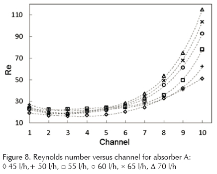
As it can be noticed, there are big differences in the Reynolds numbers. The results show a difference of 42 units between channel 1 and channel 10 for a 45 l/h flow, and for the maximum simulated flow (70 l/h) the difference is 90 units. It can be considered that there are low velocities for the first 7 channels compared to channels 8, 9 and 10. Therefore, even if the temperature at the different channels is similar, the main heat contribution to the thermo tank is made mostly by the last 3 channels from left to right in Absorber A.
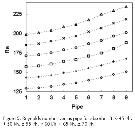
For Absorber B, the Reynolds numbers are higher (Figure 9) because, according to the CFD simulation, the velocity is higher compared to Absorber A. The variation of the Reynolds numbers between channel 1 and channel 9 for a flow of 45 l/h is 22 units, and for the maximum simulated flow (70 l/h) the difference is 36 units. Therefore, it will have similar performances for all pipes, each of them transferring similar amounts of heat to the thermo tank. This isa possible reason why it has better flow values and consequently, higher temperature values at the thermo tank, due to the possibility of better fluid mechanics performance.
Comparisons with previous work
Selmi et al. (2008) conducted a research on solar collectors. A 0.0127 m copper pipewas placed inside a wooden housing with a glass cover. The heat absorber was composed of the copper pipe and a sheet of aluminum with a polyurethane base at the bottom. This single-pipe solar collector was exposed to sunlight radiation to heat up water with a heat flow of 540 W/m2; the water temperature measured experimentally was 326 K and the simulated one 327 K. For the same calculated heat flow using the equations in this investigation, the result was 331 K. The variation of 4 K of temperature may be due to differences between the materials used in the construction of the prototype and design considerations. For his analysis, Selmi used the finite element method to validate the CFD results. On this basis, CFD is considered a consistent solving method for this research work.
Fan et al. (2007) investigated the performance (experimentation and CFD simulation) of a U-type solar collector, where the flow passes through a rhombusshaped cross section in a 16-section array with this geometry. Varying the flow from 150 l/h to 1500 l/h, the velocity characteristic curves show similar performances to those shown in Figure 8, in which the farther the duct is from the fluid inlet, the higher the flow velocity is in that respective duct (for the first half of the total amount of ducts). For the other half, a mirror view of such curves can be considered because Fan used a U-type collector, while this study evaluates a Z-type one.
In the experimental work for Absorber A, the water inlet and outlet temperature was measured getting a variation of 13 K at the zenith time, while Shiteer et al. (2003) report a temperature variation of 14 K.
Conclusions
This study shows the heat transfer and fluid mechanics performance of two absorbers from experimental data. The calculated and simulated values show consistency with each other and with similar studies by different authors as well. The calculated values of water temperature for a typical day are similar for both absorbers. In the experimental data for Absorber A the highest variation is noted in the middle of the fluid path with values of 347 K, 346 K and 345 K for channels 1, 6 and 10, respectively. For equivalent locations in Absorber B the results were 345.5 K, 344.5 K and 344.5 K for pipes 1, 6 and 9, respectively. The temperature average values for each absorber were calculated from the experimental data and compared; obtaining that the temperature average variation from one absorber to the other is only 1 K. In spite of such a small temperature difference, the CFD simulation for a 50 l/h flow showed that the maximum velocity for Absorber A was 1.38 x 10⁻² m/s mainly on channels 8, 9 and 10, while for Absorber B the velocity reached values of up to 1.7 x 10⁻² m/s in the 9 pipes, which means that there is a more uniform flow in Absorber B similarly the Reynolds is a function of velocity and the results when you have flow of 70 l/h the Absorber A, Reynolds presents values from 25 to 115 for channel 1 and channel 10 respectively, having large variations in velocity, however for Absorber B under the same flow variations are 200 to 225 such that the velocity within 9 tubes is more similar when compared to Absorber A, therefore making it a more efficient heating system.
Acknowledgements
The authors are deeply thankful to Prof. Julio Gutiérrez Villarreal for his guidance, useful suggestions, and for granting access to CONACYT project No. 141889 in this study.
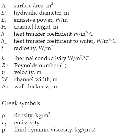
Nomenclature
References
Elshafei E.A.M., Awad M.M., El-Negiry E., Ali A.G. Heat Transfer and Pressure Drop in Corrugated Channels. Energy, volume 35 (issue 1), 2010: 101-110. [ Links ]
Fan J., Jivan-Shah L., Furbo S. Flow Distribution in a Solar Collector Panel with Horizontally Inclined Absorber Strips. Solar Energy, volume 81 (issue 12), 2007: 1501-1511. [ Links ]
Grossman G. and A. Zvirin. Heat Transfer Analysis of a Flat-Plate Solar Energy Collector. Solar Energy, volume 19 (issue 5), 1977: 493-502. [ Links ]
Holman J.P. Heat Transfer, 7th ed., New York, Mc Graw Hill, 2001. [ Links ]
Karmare S.V. and Tikekar A.N. Analysis of Fluid Flow and Heat Tranfer in a Rib Grit Roughened Surface Solar Air Heater Using CFD. Solar Energy, volume 84 (issue 3), 2010: 409-417. [ Links ]
Kumar S. and Saini R.P. CFD Based Performance Analysis of Solar Air Heater Duct Provided with Artificial Roughnees. Renewable Energy, volume 34 (issue 5), 2008: 1285-1291. [ Links ]
Naewngerndee R., Ekkachart H., Kamonpan C., Tongpool S., Jiraphong P., Sirimongkhol J. Finite Element Method for Computation Fluid Dynamics to Design Photovoltaic Thermal (PV/T) System Configuration. Solar Energy Materials & Solar Cells, volume 95 (issue 1), 2011: 390-393. [ Links ]
Rudnick A., Kaplan Y., Kudish A.I., Wolf D. A Study of Solar Collector Aging, Installation and Materials Problems. Solar Energy, volume 36 (issues 3), 1986: 227-240. [ Links ]
Selmi M., Mohammed J., Khawaja A., Abdulhamid M. Validation of CFD Simulation for Flat Plate Solar Energy. Renewable Energy, volume 33 (issue 3), 2008: 383-387. [ Links ]
Shitze A., Kalmanoviz D., Zvirin Y., Grossman G. Experiments with a Flat Plate Solar Water Heating System in Thermosyphonic Flow. Solar Energy, volume 22 (issue 1), 2003: 27-35. [ Links ]
Zhu L., Wang Y., Fang Z., Sun Y., Huang Q. An Effective Heat Dissipation Method for Densely Packed Solar Cells Under High Concentration. Solar Energy Materials & Solar Cells, volume 94 (issue 2), 2010: 133-140. [ Links ]
About the authors
Ángel Marroquín- De Jesús. He obtained his bachelor's degree in Electrical Engineering from the Oaxaca Technological Institute (in Mexico), and his master of science degree from the Morelia Technological Institute. His doctoral degree is from the National Polytechnic Institute, conferred by the Graduate Program in Advanced Technologies, CICATA-IPN, Querétaro Section. At present he is a professor at the Technological University of San Juan del Río. He has mathematically modelled, designed, and built appliances which work based on solar energy. He has published four articles in strictly refereed journals and over 60 articles in national meetings.
Juan Manuel Olivares-Ramírez. He obtained his bachelor's degree in mechanical engineering from the Morelia Technological Institute (in Mexico), and his master's degree in materials science from the same institution. His doctoral degree is from the National Polytechnic Institute, conferred by the Graduate Program in Advanced Technologies, CICATA-IPN, Querétaro Section. At present he is an associate professor at the Technological University in San Juan del Río, in the state of Querétaro. He has published four articles in strictly refereed journals. His research work has centered on methods of hydrogen production, refrigeration systems, CFD element finite, mechanic flow and heat transfer.
Omar Jiménez-Sandoval. Degree in chemistry, Faculty of Chemistry, National Autonomous University of Mexico, August 1992. Honorable mention. PhD in chemistry (inorganic chemistry), Faculty of Chemistry, National Autonomous University of Mexico, September 1997. Research stay, Department of Chemistry and Biochemistry, University of Texas at Austin, EUA, September-December 1995. Research areas: design, synthesis and structural characterization of new electrocatalystsfor fuel cell polymer electrolyte membrane. Obtaining of metal oxides by the sol-gel technique and their structural characterization, optical and morphological characteristics for various applications. Preparation and characterization of thin films of various materials by RF sputtering technique for application in optoelectronic devices.
Marco Antonio Zamora-Antuñano. He holds a master in educational sciences. He is professor and full-time researcher at the Technological University of San Juan del Rio in Mexico. It is also a professor of graduate studies at the Universidad del Valle de Mexico. He was president of the Academy of Graduate Studies at the Universidad del Valle de Mexico. He has over 10 years experience in teaching. He is chairman of faculty of Management Systems Quality. His main research interests are the quality of education and evaluation, and development of quality systems.
Armando Encinas-Oropesa. He obtained his bachelor's degree in physics at the University of Sonora (88-92). Master of science (physics) at the Institute of Physics, University of San Luis Potosi (93-95). Doctoral studies in materials science were performed at the University of Paris Sud, Orsay, France (95-99). Subsequently 3-year postdoctoral fellowship at the Department of Physical Chemistry and Physics of Materials at the Catholic University of Leuven in Belgium (99-02). Research professor at the Institute of Physics, University of San Luis Potosi in 2002. The research conducted is aimed at manufacturing and metal magnetic nanomaterial and the study of magnetic properties of magneto-resistance.

