


Services on Demand
Journal
Article
 English (pdf)
 Article in xml format
 Article references
 Send this article by e-mail
Indicators
-
 Cited by SciELO
 -
 Access statistics
Related links
-
 Similars in
SciELO
Similars in
SciELO
Share

 Permalink
Ingeniería, investigación y tecnología
On-line version ISSN 2594-0732Print version ISSN 1405-7743
Ing. invest. y tecnol. vol.11 n.3 Ciudad de México Jul./Sep. 2010
Ordered Hunt Schemes for Overlaid CDMA Cellular Systems
Esquemas de ordenamiento en sistemas celulares sobrepuestos CDMA
Castañeda–Camacho J.1 y Lara–Rodríguez D.2
1 Electronic Department Communications Area, Benemérita Universidad Autónoma de Puebla, Puebla, México, E–mail: jcastane@ece.buap.mx
2 Electrical Engineering Department Communications Section, Instituto Politécnico Nacional. México DF, E–mail: dlara@mail.cinvestav.mx
Recibido: noviembre de 2008
Aceptado: septiembre de 2009
Abstract
The CDMA overlay concept, has been proposed as one alternative to take advantage of the bandwidth available in narrowband systems. In fact, the basic idea of the CDMA overlay is to allow to wideband CDMA wave forms, to share a common spectrum with narrowband conventional wave forms. In this work, we have focused in the analysis of the performance of the forward link of the CDMA and TDMA systems when they are overlaid. In our model, in order to limit the interference into the CDMA layer caused by the TDMA system, the use of notch filters has been considered. However, one drawback of the filters is that it rejects only one part of the interference generated by the TDMA system. Therefore, we have proposed two new ideas of reduction of the interference which can not be eliminated by filters; ordered hunt and real location of the slots. Finally, we present an analytical evaluation of the forward link capacity of the systems involved in the overlaid process, due to this is the limiting link and as a function of the outage probabilities. Practical considerations such as power requirements, power control, handoff, the offered load for different services and scenarios are also addressed.
Keywords: Overlaid system, CDMA performance, TDMA, ordered hunt.
Resumen
La sobreposición CDMA ha sido propuesta como una alternativa para el aprovechamiento del ancho de banda disponible en sistemas de banda angosta. Dentro de este contexto, la sobreposición implica que las formas de onda de banda ancha de un sistema CDMA puedan compartir la misma banda espectral que las formas de onda convencionales de banda angosta. Ahora bien, en este trabajo nos hemos enfocado en presentar el análisis del desempeño del enlace de bajada de un sistema CDMA y TDMA cuando se sobreponen. Con el objeto de limitar la interferencia dentro del sistema CDMA causada por el TDMA, en nuestro modelo estamos considerando la presencia de filtros notch. Sin embargo, una de las desventajas de este tipo de filtros es que solamente eliminan una parte de la interferencia generada por el sistema TDMA. Por lo tanto, hemos propuesto dos ideas novedosas que nos permitirán reducir la interferencia que no puede ser eliminada por el uso de filtros, las cuales hemos denominado ordenamiento y reasignación de ranuras. Finalmente, presentamos una evaluación analítica de la capacidad del enlace de bajada de los sistemas involucrados en el proceso de sobreposición, debido a que este es el enlace limitante y en función de la probabilidad de falla. Diversas consideraciones prácticas como requerimientos de potencia, control de potencia, transferencia de llamada cargas de tráfico para diferentes servicios y diferentes escenarios están incluidos.
Descriptores: sistema sobrepuesto, desempeño CDMA, TDMA, hunt ordenado.
Introduction
The continuous growth in the traffic volume and the emergence of new services are increasing the rate of change of the wireless networks. To appreciate the growth of the wireless sector; notice that in 1990 only, they existed 10 million of cell phone suscribers mostly using analog FM technology. To day, there are al most one billion of suscribers and it is expected to increase to more than two billion of subscribers in next years. In China alone, more than 15 million cell phone subscribers are being added each month; more than the cumulative number of wireless suscribers that existed throughout the entire world in 1991 [1–3]. With the expected wireless revolution in telecommunications, the efficient use of the available spectrum is crucial. One step in this direction is the spread spectrum overlaid, which could be utilized as an easy migration path toward third generation cellular systems (for example IS–136 to CDMA2000 or GSM to WCDMA).
A big number of authors have explored the performance of the CDMA overlaid systems. For example; one of the first works describe the results of both propagation and field strength measurements, to demonstrate that broadband CDMA wave forms can coexist in the same frequency band with conventional microwave narrowband system and thus to increase the overall spectral efficiency in that frequency band [4]. However, we have observed that all the experiments and performance analysis have had the following fundamental goals [4–46].
a) Verify that the spread spectrum overlay would not cause excessive interference to the narrowband system.
b) Verify that the spread spectrum system can operate efficiently in the presence of the interference produced by the narrowband system.
In the literature, the overlay problem has been widely explored specially for CDMA systems.
For example, some papers have developed the performance of the overlay of CDMA and microwave systems [5–11]. In others, the performance of the CDMA overlay with FDMA or TDMA systems has been studied in terms of analytical models, which quantify a deterministic SIR ratio for very simplified scenarios [12–18].
In order to successfully implement the overlay of the systems, in a manner such that neither set of users causes excessive interference to the other set; it has been proposed the use of notch filters at the CDMA transmitters and receivers.
A big number of authors have explored the performance of the interference suppression filters in the CDMA overlaid systems [19–39]. Some of these studies have concentrated on quantifying the SIR ratio at the filter output, and others have obtained the bit–error–rate (BER) performance.
As a way to improve the performance of the CDMA overlay, other authors examine the use of multicarrier CDMA [40–44]. An other proposed alternative is the use of frequency–diversity spread spectrum (FD–SS) [12, 44]. One of the most recent proposals is the signal level clipper in the CDMA transmitter and receiver [45–46].
Motivated by the fact that most of the existing works are done partially through measurements, simulations and very simplified analytical models; the first objective of our work is to establish a mathematical model to derive the performance in terms of the Erlang capacity of the overlaid system.
Therefore, we will evaluate the capacity of the overlaid CDMA and TDMA systems considering the Poisson nature of the arrivals, the service activity detection, imperfections on the power control loop, handoff, the effect of the adjacent cell interference, and the use of suppression filters. Our second objective is to show that the interference not rejected by the filters is quite harmful for the overlaid system. Nevertheless, we have proposed a new mechanism to reduce the interference effect, which implies the ordering and reallocation of the TDMA slots1.
The paper is organized as follows. In Section II we present the system model and the overlay situation to be considered including the two new proposals. In Section III and IV the performance of the forward link is evaluated. Section V presents numerical results of the capacity estimation for different scenarios. Finally, Section VI gives our conclusions and remarks.
Sistem model
In this work two layers of CDMA and TDMA macrocells are spectrally overlaid. Base stations of both systems are located in the same position and the use of sectored antennas is assumed. The mobile users are uniformly distributed within the cells, and all cells operate at 100% loading.
To make possible the overlay situation, notch filters are placed on the CDMA mobile transmitter and base station receiver. In addition two new proposals are investigated; the ordered hunt and ordered hunt with real location of the slots, in order to reduce the probability of occupation of the TDMA co–channel slots (slots inside the CDMA bandwidth) and increase the overlay system capacity. In particular, the ordered hunt scheme assumes that the TDMA slots are numbered 1, 2,..., NTS (NTS is defined as the total available TDMA slots) in a way that co–channel slots are placed at the end of the list. Consequently, each incoming user takes the lowest–numbered idle slot. In the slots reallocation strategy, in addition to which the co–channel TDMA slots are placed at the end of the list, if one slot is set free among the first m ordered busy slots the user who occupies the m–th slot (final position) will be reallocated to the released position.
The rest of the section will be devoted to the requirements of the CDMA and TDMA systems and to the derivation of the probability density function of the number of active TDMA users inside the WC bandwidth.
CDMA system
In the CDMA system, the energy to interference ratio requirement denoted by (Eb /I0), is considered a variable different for each service. In the system, NS will denote the number of services present in the spreading bandwidth, WC. Thus, the transmission rate Rk and the required (Eb /I0)k(req) define the kth class of service for 1<k< Ns. In the CDMA system the co–channel interference received from the outside of the cell will be modeled as fc times the total power received from the intra–cell, in the forward link (fc is defined as the other cell interference factor). Some other important assumptions are:
a) A log–normal random variable, εk (with parameters of its characteristic Gaussian random variable, mean mk and standard deviation σk), will model the variable (Eb/I0)k of each user. Then, some typical values are, σk =1.5dB and mk =(Eb/I0)k(req) [50–52].
b) The number of active calls for each class of service k is modeled through a Poisson random variable, with mean the offered load denoted by (λ / τ)C(k) = aC(k). In previous equation, λ is the arrival rate, and τ is the call duration.
c) The activity factor for each k class of service is modeled as a binary distributed random variable, vk, with P(vk =1)= ρk.
TDMA system
In the TDMA system we consider a frequency reuse factor KT, it means that the total system bandwidth will be divided in KT groups of frequency, each one consisting of a number of channels separated in frequency. Therefore, we assume that the TDMA system supports a maximum of NTS users per sector, given by
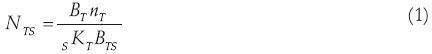
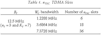
where BT is the TDMA available bandwidth, nT is the number of TDMA time slots per carrier, KT is the reuse factor of the TDMA system, BTS is the bandwidth of a TDMA channel and s corresponds to the number of sectors on the system. Each sector has NTS time slots of which nTSC slots are in the WC bandwidth, that is, nTSC are the co–channel time slots for the CDMA system. Depending on the WC bandwidth we have different values of the parameter nTSC as we can see on table 1.
In the TDMA system the total bit rate per user is RT kbps in an equivalent bandwidth of WT=BTS/nT [17, 18]. Thus, we can conclude that the total TDMA co–channel interference bandwidth is given by W Tcoc =sKT WT nT .
In the proposed system model, it is assumed that the CDMA bandwidth is completely overlaid by the TDMA system. This setup corresponds to a situation of practical interest in which the overlay could be utilized as an easy migration path toward third generation cellular systems; for example, IS–136 to CDMA2000 or GSM to WCDMA [14–15, 18–24].
Like the frequency bands of the narrow band interference are known, the CDMA system can reduce the interference produced by or toward the TDMA system by employing notch filters at the CDMA receivers or transmitters respectively (figure 1).
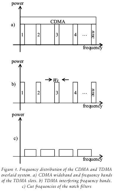
However, such filters also reduce the effective available spread bandwidth of the CDMA system. If a fraction p of the original available spread bandwidth of the CDMA system is filtered, the resulting effective CDMA bandwidth is

wherein, for ideal notch filters p = (nTSC*WT)/WC. From the CDMA cell of interest, each TDMA cell except the co–channel cells has a different group of nTSC interfering slots, in this manner, the use of notch filters can reduce the interference produced by TDMA system only on the desired and co–channel cells (in the evaluation we assume an effective co–channel TDMA bandwidth WTcoc,ef which excludes the frequency bands assigned to the desired and co–channel cells).
The same situation occurs from the TDMA cell point of view, where the interference only is reduced in the CDMA cells that overlap the desired and co–channel TDMA cells.
TDMA without ordered hunt
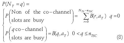
The proposed TDMA system has NTS available slots per sector, from which nTSC slots are inside the WC bandwidth. Therefore, the probability density function of the number of active TDMA users, NT, inside the WC bandwidth denoted as P(NT =q) for 0≤q≤nTSC, is expressed as
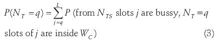
where L is the maximum occupancy for NT=q, which is given by (N TS –nTSC ) + q· TSC =NTS –nTSC are the slots outside of the WC bandwidth, therefore in (3) we have
P(from NTS slots j are bussy, NT =q slots of j are inside WC)=
P(from NTS slots j are bussy)P(NT =q slots of j are inside WC /from NTS slots j are bussy)=
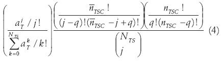
where aT is the TDMA load given by the product of the arrival rate, λT, and the mean service time, 1/τT. In figure 2 we show the probability density function of NT for two different TDMA loads and for WC=1.2288MHz. Notice that when the TDMA load increases the probability of occupation of the TDMA co–channel slots also increases. Thus, it was necessary to reduce the TDMA load until values that would make possible the operation of the overlaid system. Therefore we have evaluated two different load conditions
a) The maximum TDMA load that the system can offer for a blocking probability of 2%, given by aT=48.7 Erl.
b) One scenario in which we have approximately one half of the maximum load (partial value), given by aT=25Erl. This value originates a blocking probability of 3.0135e–009.
Finally, the probability that the q–th slot is busy is [53]
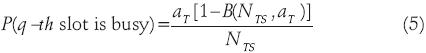
wherein B(NTS,aT) is the Erlang loss formula for NTS busy slots.
TDMA with ordered hunt
For the ordered hunt scheme we assume that the TDMA slots are numbered 1, 2,...,NTS in a way that co–channel slots are placed at the end of the list, and each incoming user takes the lowest–numbered idle slot. Thus, we can model the slot occupancy as a Markov chain with 2NTS states, as we can see in figure 3, wherein the general macrostate Eu represents the number of busy slots in the system, for u=0,...,NTS. The microstates of the form (0,0,...,0) represent all the possible positions of occupancy of u slots. Then for u=0, the state (0,0,...,0) represents the non–occupancy of the slots. For u=1 the states (1,0,...,0) to (0,0,...,1) models the occupancy of one slot, from the first position to the final position. We follow in this way until the value, u=NTS, for which the state (1,1,...,1) models the occupancy of all the slots. In general, each Eu is integrated by a group
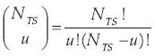
of states, which are representing all the possible positions of occupancy of u slots.
We can model this ordering through the Markov chains of figure 3, from which we find the probability density function of the number of active TDMA users inside the WC bandwidth. Therefore, the P(NT=q), is found directly from the probability of being in each microstate.
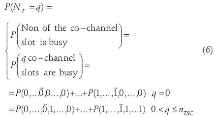
where the mark  indicates the position of the last non co–channel slot given by the difference NTS–nTSC. In (6) the probability to be in each microstate was obtained with a simulation because the analytical solution is not tractable. Figure 4 shows the P(NT=q) considering ordered hunt, for maximum and partial TDMA loads. As we can observe, especially for the partial TDMA load the occupation probability of the non co–channel slots is drastically incremented. Associated to this we have an improvement of the system performance.
Finally, in the ordered hunt [53]

where aT is the TDMA load and B(q,aT) is the Erlang loss formula for q ordered busy slots.
TDMA with ordered hunt and reallocation of the slots
In the slots reallocation strategy the co–channel TDMA slots are placed at the end of the list, but if one slot is set free among the first m ordered busy slots the user who occupies the m–th slot (final position) will be reallocated to the released position. In this strategy, as we force to the system to remain in the microstates (0,0,...,0), (1,0,...,0), (1,1,...,0),...,(1,1,...,1) the system can be modeled with a Markov chain with NTS+1 states.
As we can see in figure 5, each microstate corresponds with the general macrostate E0,...,ENTS of an Erlang loss system.
Hence, we find that the probability density function of the random variable, NT, is given by
where B(q,aT) is the Erlang–B formula, given by
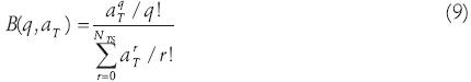
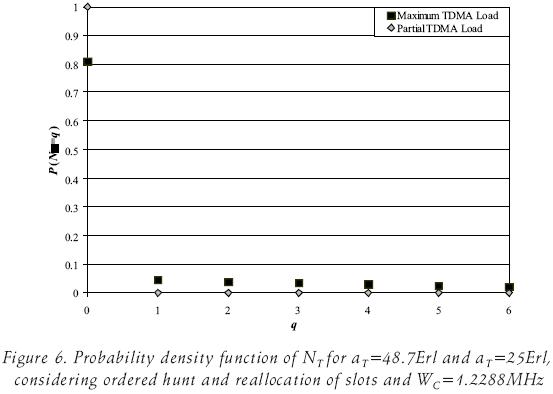
for aT the TDMA load. Figure 6 shows the probability density function of the number of active TDMA users. Notice that due to the reallocation strategy the occupation probability of non co–channel slots is incremented in comparison with the previous schemes.
Additionally, we have that
where B(r,aT) is the Erlang–B formula.
Forward link performance
CDMA performance
The forward link capacity depends on the power that is available for the traffic channels [54–56]. Typically, the power allocation to each overhead channel is determined from experimental tests. To maximize the capacity of the forward link, it is essential to control the power of the cell in order to allocate the power to an individual mobile according to its needs. Then, for the user 1 of the service k=i, the received bit energy to interference density ratio will be
where WCef is the effective spreading bandwidth, Ri is the transmission rate of the i–th class of service, c0i(1) is the fraction of the total power received by user 1 of class i from the 0–th base station. IC,CWCef and IC,TWTef are the interference power in the CDMA user due to CDMA and TDMA base stations respectively and N0WC is the power of the thermal noise. In (11) we have
where Fi(1) represents the impact of the loss of orthogonally at user 1 of class i in the downlink and Fi(1) [0,1]. This term is often referred as the multipath loss factor of the radio channel [54–56], and it is the measure of the degree of orthogonally among the own cell signals received by a particular user. Hence, Fi(1) =0 indicates that the orthogonally of the own cell signal is maintained at the receiver, while 0<Fi(1)≤1 corresponds to the case where the orthogonally is partly or fully destroyed. Ns and NBS are the number of services and the number of interfering base stations included in the system, respectively. Ni and Nk are the CDMA users of the i–th and k –th service modeled as Poisson random variables. Iotheri(1) is the individual other cell interference at user 1 of class i. We assume that the fraction of the total power received by user 1 from its CDMA control power base station is
where ωi(1) is the downlink resource consumption of user 1 of class i and c0 is the total power received by user 1 from its CDMA power control base station.
The interference power in the CDMA user due to TDMA base stations is given by
where T l(j) is the power designed to the j–th user on the l–th TDMA base station received by user 1 of class i. NBS – NBS,coc is the number of interfering base stations included in the system.
Solving (11) with (12), (13) and (14), we have the following result for ωi(1)
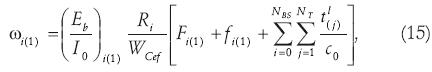
where fi(1) is the forward link other cell interference factor for the user 1 of class i. In practical systems, a fraction of the total transmitted power is devoted to the pilot channel and other common control channels destined to all users. We assume this overhead as (1–9). Therefore, the remaining fraction 9 of the total power is then allocated to all users controlled by the base station in the sector. The system will be in an outage situation if the total allocated transmission power exceeds the total available power at the base station. Then, let us define the system outage probability of the forward link as [54–56]
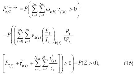
where vk is the activity of the users of the k–th service class modeled as a binary random variable and (Eb/I0)k(j)=E is a log–normal random variable that defines the required (Eb/I0) of the j–th user of the k–th service class. Using the central limit theorem in (16), Z can be approximated as a Gaussian random variable. Since fi(j) depends on the position of the users, we approximate the estimation by taking the average at all the locations in the sector. Thus, the outage probability is given by

where θ is the fraction of the total transmitted power dedicated to the traffic channels, typically between 71% and 80% [55]. Soft handoff on the forward link makes the power allocation even more complicated. For simplicity, we assume that a fraction g<1 of all users is in soft handoff and a maximum of three base stations involved in the process [54]. For each user in soft handoff, we assume that the base stations in volved allocate the same power fraction to that user. Then, the number of users in each cell is increased by 2g because of soft handoff.
The values E{Z} and Var{Z} are the following
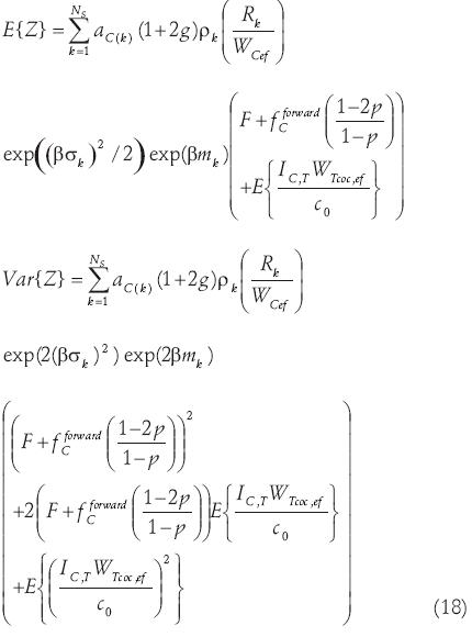
where aC(k)(1+2g) is the traffic load of the CDMA system, ρk is the activity factor of the k–th class of service, β=ln(10)/10,σk = 1.5 dB, mk =(Eb/I0)k(req), fCforward is the other–cell interference factor of the CDMA system. For the case in which we use notch filters, the other–cell interference factor is affected by (1 –2p /1 – p). F is the impact of the loss of orthogonally whose value depends on the specific scenario, e.g. F=0.4 in a vehicular scenario and F=0.06 in a pedestrian scenario [54].
In (18), the values E{ITC WTcoc,ef / c0 } and E{(ITC WTcoc,ef / c0 )2} are obtained as suming two different scenarios; the TDMA system without power control and with power control.
We have that the received power on the interest CDMA user from the l–th BS is
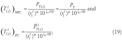
where PT is the transmitted power by the TDMA base station per user, and (r1l)µ 10ζ1/10 models the propagation losses given by the product of the µ–th power of the distance between the CDMA interest user and the l–th base station and a log–normal component representing shadowing losses where ζ 0 is the dB attenuation with zero mean and standard deviation Δ.  is the average TDMA transmitted power by the l–th base station which power controls to the j–th user, and which is given by
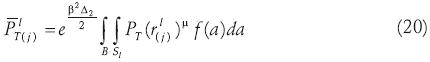
where (rl(j)) is the distance between the l–th base station and all the possible positions of the j–th TDMA user inside of the coverage area of the l–th BS and f(a)=1 / cell area.
Let us assume a log–normal approximation for the value by the Schwartz and Yeh method. Then in equation (18) we have
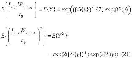
where E{y} and S{y} are the mean and standard deviation of the random variable which characterize to Y and change in accordance to the non power control scheme or power control scheme used in the TDMA layer.
CDMA Performance
As the outage probability of the forward link, (17), is a function of the position of the CDMA user of interest, we have obtained an average over a large set of mobile positions inside its coverage area. Then
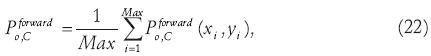
where Max is the total number of mobile positions.
TDMA performance
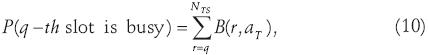
For the TDMA system we evaluate the probability of not having an adequate signal to interference ratio, SIRT(req), known as the outage probability. Hence, the outage probability due to the q–th slot is busy, is given by
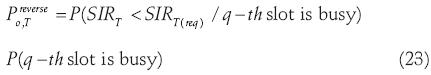
where in accordance with the slots allocation scheme we can know the P(q–th slot is busy). Then, we follow to obtaining
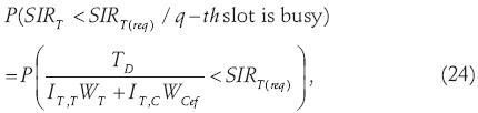
where TD is the power of the desired signal on the TDMA system, IT,TWT and IT,CWCef, are the powers of the interference in the TDMA system due to TDMA and CDMA systems respectively. In (24)
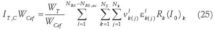
where Nk is a Poisson random variable which models the CDMA active users. vlk(j) and εlk(j) are a binary and log–normal random variables which defines the activity of the services and the (Eb/I0) of the j–th user of the k–th class of service in the l–th base station respectively. Rk is the bit rate requirement of the k–th service and (I0)k is the CDMA interference spectral density for the k–th service. WT is the equivalent TDMA slot bandwidth and WCef is the effective spreading bandwidth. Again, the evaluation of (24) is conditioned to the consideration or not of power control in the TDMA layer.
TDMA System without and with power control
Without power control
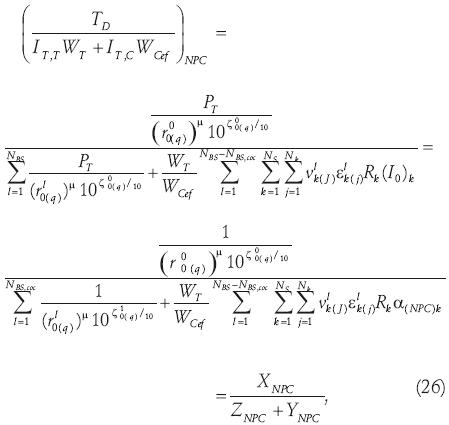
where α(NPC)k is the ratio between CDMA spectral interference density received in the base station for the k–th service and the TDMA transmitted signal power. Additionally in (26) we have approximated XNPC by a log–normal random variable, whose characteristic Gaussian random variable has the mean and standard deviation
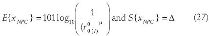
The random variable ZNPC is approximated as a Gaussian random variable invoking the central limit theorem and YNPC by a log–normal random variable using the Schwartz and Yeh method. Therefore
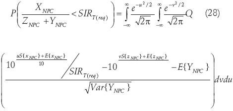
where E{zNPC} and S{zNPC} are the mean and standard deviation of the Gaussian random variable which characterize to ZNPC. The E{YNPC} and Var{YNPC}are given by
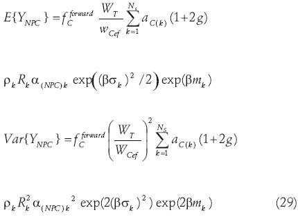
where α(NPC)k is the ratio between the CDMA spectral interference density received in the mobile for the k–th service and the TDMA base station transmitted signal power.
With power control in the TDMA layer we have
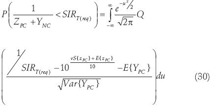
where E{zPC} and S{zPC} are the mean and standard deviation of the random variable which characterize to the log–normal variable ZPC obtained by Schwartz and Yeh method.
The E{YNPC} and Var{YNPC}are given by
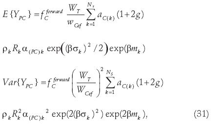
where α(NPC)k is the ratio between the CDMA spectral interference density received in the mobile for the k–th service and the TDMA base station received signal power.
TDMA performance
The outage probability is a function of the position of the CDMA user of interest. Therefore, we have obtained an average over a large set of mobile positions inside its coverage area, then
where is the total number of mobile positions.
Numerical results
In this section, we evaluate the performance of the forward link of the CDMA and TDMA overlaid system. All of our evaluations consider different values of the ratios γ and α, the service time on the TDMA layer equal to 2 minutes, Δ=8dB, µ=4, fCforward =0.3632 (when 3 BS are participating in the soft handoff) and all the parameters listed on the table 2.
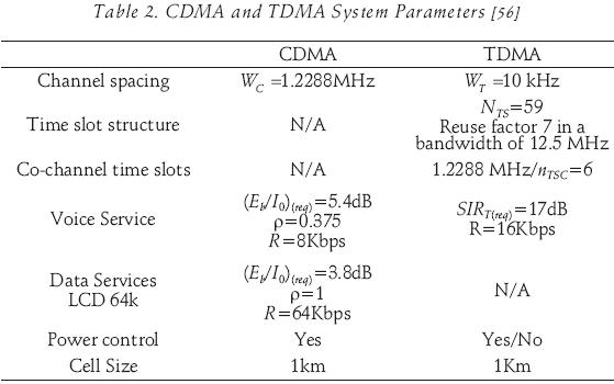
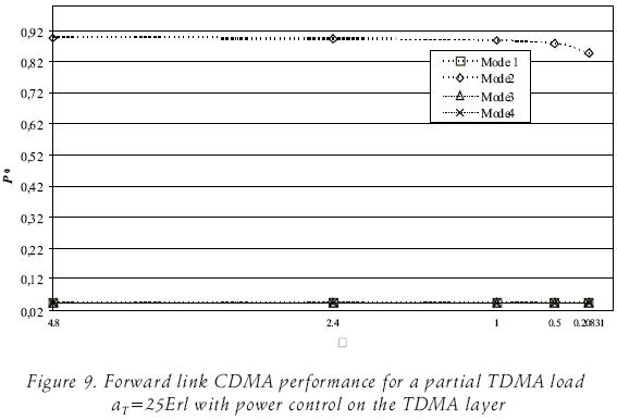
In the numerical evaluations we have considered two different settings, the TDMA layer with and with no power control. Also, we have considered four models of evaluation of the overlaid system. In the mode 1, it has been evaluated the isolated CDMA or TDMA systems. In the mode 2, it has been evaluated the overlaid system which is operating with the normal allocation of the slots in the TDMA layer. In the mode 3, it has been evaluated the overlaid system when it implements ordered hunt in the allocation of the TDMA slots. Finally in the mode 4, it has been evaluated the overlaid system when the TDMA layer implements the ordered hunt and relocation of the slots.
We evaluate the performance of the CDMA system for two types of services in the presence of the TDMA system. We have considered a maximum capacity in the CDMA layer given by, aVoice = 16.44 Erl and aData=1 Erl for a blocking probability of around 2%. The TDMA system has been evaluated when it operates at a tolerable capacity, aT=25 Erl for a blocking probability less than 2%.
Table 3 show the CDMA and TDMA power requirements for different values of the γ and α ratios. As we mentioned previously γ and α ratios, depend on the link and the power control, and are given as parameters. In the forward link without power control on the TDMA layer, γNPC is the ratio between the transmitted power by the TDMA base station per user and the total power received by CDMA user from its CDMA power control base station and α(NPC)k is the ratio between the CDMA spectral interference density received in the mobile for the k–th service and the TDMA base station transmitted signal power.
With power control on the TDMA layer, γpc is the ratio between the average transmitted power by the TDMA base station per user and the total power received by CDMA user from its CDMA power control base station, and a α(PC)k is the ratio between the CDMA spectral interference density received in the mobile for the k–th service and the TDMA base station transmitted signal power.
In table 3 as a way to approximate the parameter α, we assume that the maximum tolerable CDMA spectral interference density is given by Ikα(max) =PCDMArx /Rk)/(Eb / I 0 ) k . Where Rk and (Eb / I 0 )k are the bit rate and the required bit energy to interference density ratio.
No power control on the TDMA layer: Forward link performance
For this macrocell scenario, the performance of the overlaid system when it has maximum load in the TDMA layer is poor, therefore in those conditions it is impossible the operation of the system. Figures 7 and 8 show the CDMA and TDMA performance of the forward link for two classes of services in the presence of the TDMA system when aT=25Erl, for a blocking probability of 2% in CDMA layer and less than 2% in TDMA layer.
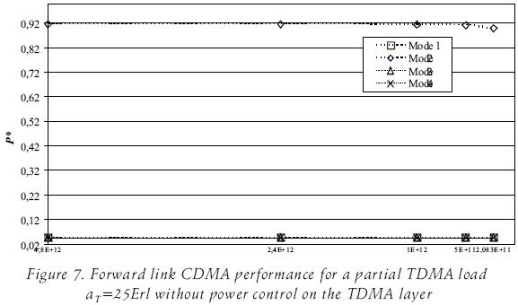
Notice that, although for the normal al location of the slots the operation of the system is impossible due to the poor performance; we can observe that in the CDMA layer in agreement the ratio g decreases, we have a better performance of the overlaid system because of the reduction in the TDMA transmitted power or the increment in the CDMA transmitted power. The same situation occurs with the ratio α, in agreement this goes a decrement, the TDMA layer has a better TDMA performance.
A significantly improve on the performance of the overlaid system is observed when the system implements the ordered hunt or slots reallocation strategies.
Power control on the TDMA layer: Forward link performance
Figures 9 and 10 show the performance of the CDMA and TDMA layers when we consider the partial load condition and power control in the TDMA layer. Because of the power control in the TDMA layer, the operation of the overlaid system under more realistic conditions in terms of power requirements and quality levels is possible for both strategies, ordered hunt and reallocation of the slots.
Capacity gain
To improve the overlaid system performance we have considered a TDMA load aT=25 Erl. Then, from previous results we can conclude that the co–channel ordered slots strategies and the power control scheme on the TDMA system increase the total system capacity in a factor equal to 1.25 This is possible for a CDMA performance P0<10% and a TDMA performance P0<16%.
If better conditions of quality are required, the offered load of the TDMA layer can be reduced.
Conclusions
From the results we can observe that in the assumed macrocell scenario, the overlay situation is not possible if only filtering is used. Therefore, in addition to the filtering techniques which are not enough to reduce the impact of the interference between the layers of the overlaid system, two new ideas the ordered hunt and slots reallocation of the TDMA co–channel slots were proposed. Thus, it was theoretically shown that the CDMA overlaying can increase the total system capacity because of the power control in the TDMA layer and the slot allocation strategies.
In this work we have obtained general expressions of the performance of the forward link for different scenarios as a function of the γ value, which is the limiting factor on the overlaid capacity. In fact, with smaller γ ratios, higher capacities of the overlaid system can be achieved. Without power control on the TDMA layer the overlaid system has a poor performance. Then, from previous results we can conclude that the co–channel ordered slots strategies and the power control scheme on the TDMA system increase the total system capacity in a factor equal to 1.25 This is possible for a CDMA performance Pb<10% and a TDMA performance P0<16%.
References
[1] Rappaport T.S., Annamalai A. et al. Wireless communications: Past events and Future Perspective. On: IEEE Commun. Magazine, 50th Anniversary Commemorative Issue, pp. 148–161, May 2002. [ Links ]
[2] Esmailzadeh R., Nakagawa M. TDD–CDMA for the 4th Generation of Wireless Communications. On: IEEE Wireless Commun., pp. 8–15, August 2003. [ Links ]
[3] Rappaport T.S. Wireless Communications, Principles and Practice. 2d Ed. NJ. Prentice Hall. Upper Saddle River. 2002. [ Links ]
[4] Milstein L.B., Schilling D.L., Pickholtz R.L. et al. On the Feasibility of a CDMA Overlay for Personal Communications Networks. IEEE J. Select Areas Commun., 10:655–668, May 1992. [ Links ]
[5] Filis K.G., Gupta S.C. Overlay of Cellular CDMA on FSM. IEEE Trans. On Veh. Technol., 43(1):86–98, Feb. 1994. [ Links ]
[6] Wang J. Cellular CDMA Overlay Situations. IEE Proc.–Commun., 143(6):389–395, Dec. 1996. [ Links ]
[7] Wang J. LMS Filters for Cellular CDMA Overlay. On: International Conference on Commun. ICCT, pp. 366–369, 1996. [ Links ]
[8] Ywh–Ren T., Jin–Fu Ch. Feasibility of Adding a Personal Communications Network to an Existing Fixed–Service Microwave System. IEEE Trans. On Commun., 44:76–83, Jan. 1996. [ Links ]
[9] Schilling D.L., Milstein L.B., Pickholtz R.L. et al. A Spectrally Efficient CDMA Overlay. MILCOM. 1997. Pp. 1183–1185. [ Links ]
[10] Shad A., Haimovich A.M. Performance of Space– Time Receiver Architectures for CDMA Overlay of Narrowband Wave forms for Personal Communications Systems. On: International Conference on Commun. ICC, 1997, pp. 314–318. [ Links ]
[11] Papproth E., Kaleh G.K. A CDMA Overlay Using Frequency Diversity Spread Spectrum. IEEE Trans. Veh. Technol., 48(2):397–404, March 1999. [ Links ]
[12] Schilling D.L., Lomp G.R., Garodnick J. Broad band CDMA Overlay. On: IEEE Vehicular Technology Conference VTC, 1993, pp. 452–455. [ Links ]
[13] Grieco D.M., Garodnick J. y Schilling D.L. Capacity Limitations due to Adjacent Cell Dissimilar Technologies. MILCOM. 1993. Pp. 543–549. [ Links ]
[14] Grieco D.M. The Capacity Achievable with a Broadband CDMA Micro cell Underlay to an Existing Cellular Macrosystem. IEEE J. Select Areas Commun., 12(4):744–750, May 1994. [ Links ]
[15] Parsa K., Zadeh S.G. B–CDMA Overlay Forward Link and Reverse Link Capacity Based on Random Traffic and a New CDMA Call Blocking Model. GLOBECOM. 1995. Pp. 2171–2176. [ Links ]
[16] Hmimy H.H., Gupta S.C. Overlay of Cellular CDMA on AMPS Forward and Reverse Link Analysis. IEEE Trans. Veh. Technol., 45(1):51–56, Feb. 1996. [ Links ]
[17] Wu J.S., Sze M.T., Chung J.K. Uplink and Downlink Capacity Analysis for Two–Tier CDMA Cellular Systems. IEEE Vehicular Technology Conference VTC. 1997. Pp. 626–633. [ Links ]
[18] Chih–Lin I., L.J. Greenstein, Gitlin R.D. A Microcell/ Macrocell Cellular Architecture for Low– and High–Mobility Wireless Users. IEEE J. Select Areas Commun., 11(6):885–891, August 1993. [ Links ]
[19] Grieco D.M., Schilling D.L. The Capacity of Broad band CDMA Overlaying a GSM Cellular System. On: IEEE Vehicular Technology Conference VTC, 1994, pp. 31–35. [ Links ]
[20] Widdowson T. A CDMA Data Overlay of the GSM Network. On: IEEE International Symposium on Published PIMRC, 1997. [ Links ]
[21] Moelker D.J., Prasad R. Capacity of Co–existent Cellular CDMA and GSM with Shadowing and Imperfect Sectorization, Power Control and Notch Filtering. IEEE PIMRC. 1997. [ Links ]
[22] Koorevar P., Ruprecht J. Frequency Overlay of GSM and Cellular B–CDMA. IEEE Trans. Veh. Technol., 48:696–707, May 1999. [ Links ]
[23] Noël L., Widdowson T. Experimental CDMA Data Overlay of GSM Network. Electronics Letters, 35(8): 614–615, April 1999. [ Links ]
[24] T. Widdowson and L. Noël, "Uplink and Down link Experimental CDMA Overlay of GSM Network in Fading Environment," Electronics Letters, Vol. 35, No. 17, pp. 1440–1441, August 1999. [ Links ]
[25] Milstein L.B., Wang J. Interference Suppression for CDMA Overlays of Narrowband Wave forms. ISSSTA, 1994, pp. 61–68. [ Links ]
[26] Wang J., Milstein L.B. CDMA Overlay Situations for Microcellular Mobile Communications. IEEE Trans. on Commun., 43(2–4):603–614, Feb.–Apr., 1995. [ Links ]
[27] Wang J., Milstein L.B. Interference Suppression for CDMA Overlay of a Narrowband Wave form. Electronic Letters, 31(24):2074–2075, Nov. 1995. [ Links ]
[28] Rainbolt B.J., Miller S.L. CDMA Transmitter Filtering for Cellular Overlay Systems. IEEE Trans. on Commun., 48(2):290–297, Feb. 2000. [ Links ]
[29] Wei P., Zeidler R., Ku W.H. Adaptive Interference Suppresion for CDMA Overlay Systems. IEEE J. Select Areas Commun., 12(9):1510–1523, Dec. 1994. [ Links ]
[30] Gottesman L.D., Milstein L.B. On the Use of Interference Suppresion to Enhance Acquisition Performance in a CDMA Overlay Scenario. On: IEEE Vehicular Technology Conference VTC, 1995, pp. 1219–1223,. [ Links ]
[31] Gottesman L.D., Milstein L.B. The Coarse Acquisition Performance of a CDMA Overlay System. IEEE J. Select Areas Commun., 14(8):1627–1635, Oct. 1996. [ Links ]
[32] Wang J. On the Use of a Suppresion Filter for CDMA Overlay. IEEE Trans. on Veh. Technol., 48(2). 405–414, March 1999. [ Links ]
[33] Yu A., Wang J. CDMA Overlay in the Presence of Power Control Error. On: IEEE Vehicular Technology Conference VTC, 1999, pp. 1831–1835. [ Links ]
[34] Ugweje O.C., Matin S.A. Performance of CDMA Overlay Systems Using Filtering and Diversity. IEEE Trans. on Veh. Tecnol., 52(2):456–462, March 2003. [ Links ]
[35] Kim J.Y., Lee J.H. Performance of PN Code Acquisition in a DS/CDMA Overlay Environment with Imperfect Power Control. On: IEEE Vehicular Technology Conference VTC, 1997, pp. 108–2112. [ Links ]
[36] Moeneclaey M., Bladel M.V., Sari H. Sensitivity of Múltiple–Access Techniques to Narrow–Band Interference. IEEE Trans. on Commun., 49(3):497–505, March 2001. [ Links ]
[37] Poor H.V Active Interference Suppresion in CDMA Overlay Systems. IEEE J. Select Areas Commun., 19(1):4–20, Jan. 2001. [ Links ]
[38] Heiska K., Posti H. et al. Capacity Reduction of WCDMA Downlink in the Presence of Interference From Adjacent Narrow–Band System. IEEE Trans. on Veh. Tecnol., 51(1):37–51, Jan 2002. [ Links ]
[39] Rainbolt B.J., Miller S.L. The Necessity for and Use of CDMA Transmitter Filtering in Overlay Systems. IEEE J. Select Areas Commun., 16(9):1756–1764, Dec. 1998. [ Links ]
[40] Milstein L.B. The CDMA Overlay Concept. IEEE SS Techniques & Applications Proceedings, 1996. [ Links ]
[41] Kim I.G., Kim D. Spectral Overlay of Multicarrier CDMA on Existing CDMA Mobile Systems. IEEE Commun. Letters, 3(3).15–17, Jan. 1999. [ Links ]
[42] Rainbolt B.J., Miller S.L. Multicarrier CDMA for Cellular Overlay Systems. IEEE J. Select Areas Commun., 17(10):1807–1814, Oct. 1999. [ Links ]
[43] Tung W.T., Wang J. MMSE Receiver for Multicarrier CDMA Overlay in Ultra–Wide–Band Communications. IEEE Trans. Veh. Technol., 54(2):603–614, March 2005. [ Links ]
[44] Papproth E., Kaleh G.K. A CDMA Overlay Using Frequency Diversity Spread Spectrum. IEEE PIMRC. 1997. Pp. 630–634. [ Links ]
[45] Zhou J., Yamamoto U., Onozato Y. Impact of Interference Supression Techniques on Spectrum Overlaid Systems of TDMA/W–CDMA and N–CDMA/W–CDMA. IEICE Trans. Fundamentals, E84–B(3):539–549, March 2001. [ Links ]
[46] Zhou J., Kikuchi H. et al. Forward Link Performance of TDMA/W–CDMA Spectrum Over laid Systems with Interference Cancellation for Future Wireless Communications. IEICE Trans. Fundamentals, E85–A(7):1536–1545, July 2002. [ Links ]
[47] Castañeda–Camacho J., Lara–Rodriguez D. Erlang Capacity of Overlaid Multiclass CDMA and TDMA Systems. IEEE Vehicular Technology Conference (VTC 2002), 2002. [ Links ]
[48] Castañeda–Camacho J., Lara–Rodriguez D. Forward Link Capacity of Overlaid Multiclass CDMA Systems and TDMA Systems with Slots Reallocation on the TDMA Layer. IEEE Vehicular Technology Conference (VTC 2003), 2003. [ Links ]
[49] Castañeda–Camacho J., Lara–Rodriguez D. Overlay of TDMA and Multiclass CDMA Systems with Slots Reallocation on the TDMA Layer. IEEE International Conference on Communications (ICC 2003), 2003. [ Links ]
[50] Sarkar S. Reverse Link Capacity for CDMA2000. On: IEEE Vehicular Technology Conference (VTC 2001), vol. 1, pp. 123, Spring 2001. [ Links ]
[51] Zhang Q., On–Chin Y. UMTS Air Interface Voice/Data Capacity–Part 1: Reverse Link Analysis. On: IEEE Vehicular Technology Conference (VTC 2001), Vol. 1, pp. 200, Spring, 2001. [ Links ]
[52] Castañeda–Camacho J., Uc–Rios C.E., Lara–Rodriguez D. Reverse Link Erlang Capacity of multiclass CDMA Cellular System Considering Non–Ideal Antenna Sectorization. IEEE Trans. Vehic. Technol., 52(6), Nov. 2003. [ Links ]
[53] Cooper R.B. Introduction to Queueing Theory. New York. The Macmillan Company. 1972. [ Links ]
[54] Zhang Q. UMTS Air Interface Voice/Data Capacity–Part 2:Forward Link Analysis. IEEE Vehicular Technology Conference (VTC 2001), Spring 2001. [ Links ]
[55] Mückenheim J., Bernhard U. A Framework Load Control in 3rd Generation CDMA Networks. IEEE Vehicular Technology Conference VTC, Fall 2001. [ Links ]
[56] Garg V.K. Wireless Network Evolution 2G to 3G. Prentice Hall. 2002. [ Links ]
[57] Yeh Y.S., Schwartz S.C. Outage Probability in Mobile Telephony due to Multiple Log–Normal Interferers, IEEE Trans. Comm, 32(4):380–388, April 1984. [ Links ]
1 The overlay problem with ordering and reallocation is partially based on previous works [47–49].
About authors
Josefina Castañeda–Camacho. (S'99) Was born in Puebla, Puebla, México, in 1973. She received the B.Sc. degree from the Autonomous University of Puebla (UAP), Mexico, in 1996 and the M.Sc. degree from the CINVESTAV–IPN, México in 2000, and her Ph. D. degree in 2007 from the CINVESTAV–IPN, México, all in electrical engineering. Currently, she is in the Autonomous University of Puebla (BUAP) in the telecommunications research group. Her main research interests include teletraffic analysis, cellular system dimensioning and performance modeling and the evaluation of overlaid systems and packet networks.
Domingo Lara–Rodríguez. (S'97—M'00) Received his Ph. D. and M.Sc. degrees in Electrical Engineering from the CINVESTAV–IPN and the B.Sc. in Electronics and Communications Engineering from the National Polytechnic Institute of Mexico (IPN). Currently, he is with the Mobile Telecommunications Research Group in the Center for Research Advanced Studies — IPN in Mexico. His main research interests include radio resource management, performance modeling and architectural design in mobile cellular, indoor and wireless local loop systems.

