


 text new page (beta)
 English (pdf)
 Article in xml format
 Article references
 Send this article by e-mail
 Cited by SciELO
  Similars in
SciELO
Similars in
SciELO 
 Permalink
1 Introduction
The construction of densely connected groups, called communities, is a well known problem in complex networks. It has an indispensable role in several domains such as data mining [13], emergent pattern detection in terrorist networks [5], computational biology [3], etc. In order to model communities in a rigorous way, we consider maximal cliques which represent maximal subgraphs in which any pair of nodes is connected by an edge.
Until recently, several efforts have been devoted to resolve the maximal cliques problem. Most of them used centralized algorithms [15,9,14,16], but only few of them [12,7] proposed distributed algorithms.
These algorithms are designed to run on interconnected autonomous computing entities to achieve a common entities task. In fact, each entity communicates locally with its immediate neighbors and executes asynchronously the same code.
In this context, a distributed algorithm can be modeled by means of the local computation model [11]. The latter allows us to encode algorithms at a high level of abstraction independently from the network topology. In fact, an algorithm is simply given by a set of relabeling rules which are locally executed. These rules, which are closely related to mathematical and logic formulas, are able to derive the correctness of distributed algorithms.
Nevertheless, the development of distributed systems has not been well mastered yet. In fact, the modeling and the verification remain hard tasks due to the lack of knowledge of the global state and the non-determinism in the execution of the processes.
Then, ensuring the correctness of these algorithms becomes crucial because it gives us confidence that distributed systems perform as designed and do not behave harmfully.
In most of the proposed solutions [9,14,15], the reliability of the maximal clique algorithms is justified based on simulation results that can not guarantee their correctness.
Moreover, using paper-and-pencil based proofs [7,12] is a tedious task and a minor error can have serious consequences on the system operation. Furthermore, we notice that the proposed solutions in the literature do not consider any model to design their algorithms.
So, we find that it is interesting to propose a distributed algorithm for constructing maximal cliques within a network graph based on the local computation model.
To specify the abstraction provided by local computations, we have used a formal method. In fact, formal methods provide a real help for expressing correctness with respect to safety properties in the design of distributed algorithms.
Particularly, the correct-by-construction approach [10] provides a simple way to construct and prove algorithms. The main idea relies upon the development of distributed algorithms following a top/down approach controlled by the refinement of models.
This process allows to simplify the proofs and validate the integration of requirements. The Event-B modeling language [1] can support this methodological proposal by suggesting proof based-guidelines. It is supported by a tool called "RODIN" [2] which provides an environment for developing correct-by-construction models for software-based systems.
The remainder of this paper is structured as follows: Section 2 gives a review of related literature. In Section 3, we present basic concepts of the local computation models and Event-B formal method. Section 4 introduces our proposed algorithm. In Section 5, we specify this algorithm with the Event-B method. In Section 6, we conclude the paper and we give some directions for our future research.
2 Related Work
Many research studies dealt with the problem of constructing maximal cliques as it is a challenging up-to-date issue. Most of the proposed approaches are based on centralized algorithms [16,9,15], but only few have adopted distributed solutions [12,7,17]. In the following, we present some details of these solutions.
Luo et al. [12] introduced a distributed algorithm, called MC (Maximal Clique), to find all maximal cliques in a graph with linear complexity. Then, the authors used the MCP (Maximum Clique Problem) algorithm to get all maximal cliques with the same number of memberships and they computed a unique maximum clique by UMCP (Unique MCP) algorithm.
In [7], the authors presented a new technique for detecting maximal cliques in large social networks. This technique has a quasi-linear complexity. It relies on a network decomposition process based on two levels. The initial level aims to identify two sets of nodes. The first set contains the nodes of the graph whose degree is less than a certain threshold and the second includes the nodes of high degree (whose degree is greater than or equal to this threshold). The second level of decomposition consists in dividing the graph into a set of blocks. It adds to each node of low degree these neighbors to form a block. Then, the Best-Fit algorithm [6] is applied for each generated block to determine its maximum clique. The authors formally proved the correctness of their proposed solution using manual proofs.
In the same context, Wu et al. [17] proposed an algorithm for enumerating maximal cliques in exponential time based on the MapReduce technique [8]. In a first phase, this algorithm starts by extracting all possible cliques (maximal, non maximal and duplicated cliques). The second phase is based on a pruning strategy which returns only maximal cliques.
Even though many research approaches have tackled the problem of finding maximal cliques in a graph, we notice that the majority of them [17,14,15,9] rely on simulation to evaluate the performance of these solutions. Some studies [7,12] have proved the correctness of their algorithms.
However, the proofs which have been presented are done manually. These proofs are long and tedious in the case of complex algorithms.
The main contribution of our work is to propose an algorithm for constructing maximal cliques based on the local computation model.
Our algorithm is inspired by the work of Luo et al. [12] which has the lowest complexity compared to other existing algorithms. To specify and prove its correctness, we use the Event-B formal method. The strong point of this method is that it supports the incremental modeling of algorithms using the step-wise refinement concept. In fact, Event-B starts from an abstract model and introduces gradually the different properties of the system to obtain a more concrete model.
3 Basic Concepts
3.1 Local Computation Models
In this section, we illustrate the notion of local computations, and particularly that of graph relabeling systems [11,4] by showing how some algorithms on networks of processors may be encoded within this framework. A network is represented as a finite graph whose nodes stand for processors and edges for (bidirectional) links between processors. The local state of each process as well as the communication link are denoted by a label assigned to the corresponding node and edge. According to its own state and to the states of its neighbors, each node may decide to realize a computation step. After this step, the states of this node as well as its neighbors and the corresponding edges may change depending on some computation rules. Let us recall that graph relabeling systems satisfy the following conditions:
— They do not affect the structure of the underlying graph, but only the labeling of its nodes and edges.
— The locality of these interactions implies that each relabeling step can only change the labelings of a connected subgraph with a fixed size in the underlying graph.
— The local context of the relabeled graph determines if a relabeling rule is applicable or not, which means that these computations are locally generated.
There are three types of local computations for implementing distributed algorithms: (LC0) synchronizes a node with only one of its neighbors. The relabeling rule will be applied to these two nodes and the edge linking them. (LC1) synchronizes a ball of radius 1: a center node and all its neighbors at distance 1. The relabeling rule may update the label of the center node as well as those of the edges linking it to its direct neighbors. The labels of the other nodes in the ball are not modified. (LC2) synchronizes a ball of radius 1. The application of the relabeling rule can update the label of the center node, the labels of its direct neighbors and also the labels of the edges linking the center node to its neighbors.
3.2 Event-B Overview
The Event-B modeling language [1] is an evolution of the B language. A system specification (model) in Event-B consists of two types of components: context and machine. A context specifies the static part of a model and may contain carrier sets, constants, axioms, and theorems that can be derived from the axioms of a context.
An Event-B machine describes a reactive system. It may contain variables, theorems, invariants and events. The variables define the state of a machine. They are specified by invariants. The properties derivable from the invariants are called "theorems". The changes of possible state are described by events. An invariant is defined as a predicate preserved by each event. Machines can be linked to each other by a refinement relation. To have access to its elements, a context is seen by a machine and its refinements. Moreover, a context may be extended by another to introduce more elements.
The concept of refinement is the main feature of Event-B. The refinement of a machine enables to enrich it in a step-by-step fashion. It is the foundation of the correct-by-construction approach [10]. It is also used to transform an abstract model into a more concrete version by modifying the state definition. In fact, new variables and events can be introduced. Furthermore, abstract events can be refined to become more concrete.
The relation between variables in the concrete and abstract model is given by a gluing invariant.
An Event-B specification is considered as correct only if each machine as well as the process of refinement is proved by adequate Proof obligations (POs); i.e events preserve the invariant(s) and each event is feasible. POs are generated by the RODIN tool [2], which provides an environment for developing correct-by-construction models for software based systems. They can be discharged either automatically by an integrated proof tool or through interactive proof steps.
4 A Distributed Algorithm for Constructing Maximal Cliques
A network can be modeled as a simple and undirected graph G=(ND,E) where ND is the set of nodes and E is the set of edges. In this work, we suppose that every node in the graph knows its neighbors. A clique is a fully connected subgraph of the graph G, and a maximal clique is a clique that is not a subset of any other clique in the same graph.
The proposed algorithm may be encoded by the graph relabeling system R = (L, I', P) defined by L = {State, Clique}, I' = {Init, Ø}, and P = {R1, R2, R3}.
State and Clique are two functions. State gives the current state of each node and Clique assigns to each node the nodes of its maximal clique. Each node v has two labels State(v) and Clique(v):
-
— State(v) ∈ {Init, C, I, No, Alone} is the state of the node v. It can take one of these labels:
Init: the node v is in the initial state.
C: the node v detects a maximal clique. We call v "the center" of this clique.
I: the node v belongs to a maximal clique and it is different to the center of the clique.
No: the node v is in the waiting state. It has not been assigned to a maximal clique yet.
Alone: the node v does not belong to any maximal clique. It is called "isolated node".
— Clique(v)
I' is the set of initial labels and R1, R2 and R3 are the LC1 relabeling rules.
For each node v ∈ ND, we define
4.1 Rule R1
The goal of this rule is to detect a maximal clique in the graph. Let x be a node of the graph G in the initial state and R(x) containing at least three nodes. By applying the rule R1 all the nodes of R(x) form a maximal clique having as center the node x.
Then, x is labeled C and the other nodes of R(x) are labeled I. Formally, the rule R1 is written as follows1:
4.2 Rule R2
The goal of the rule R2 is to define a waiting node. It consists in modifying the state of a node from the initial state to the waiting state by giving it the label "No". Let x be a node labeled "Init".
It has R(x) containing less than three nodes and there is a node in the initial state that is a neighbor of x. By applying the rule R2, the label of the node x becomes "No". Formally, the rule R2 is written as follows:
4.3 Rule R3
This rule aims to detect an isolated node which does not belong to any maximal clique. This node is called an isolated node. The rule R3 requires the presence of a node x having the initial or the waiting state. Besides, all the neighboring nodes must not be in the initial state.
As a result, the node x is marked as "Alone" and Clique(x) contains only the node x. Formally, this rule is written as follows2:
A run of the proposed algorithm consists in applying the relabeling rules specified by the algorithm until no rule is applicable. These rules are applied asynchronously and non-deterministically, which means that given the initial labeling, many different runs are usually possible. In the final configuration, every node x (x ∈ ND) has State(x) ∈ {C, I, Alone} and Clique(x) ≠ Ø:
If x does not belong to any maximal clique, it will have State(x) = Alone and Clique(x) = {x}.
If x belongs to a maximal clique, it will have State(x) ∈ {C, I} and card(Clique(x)) ≥ 3.
An execution example of the proposed algorithm can be downloaded from this link3.
5 Formal Specification of the Proposed Algorithm
As mentioned earlier, the specification of our algorithm is performed with the Event-B method and done with the RODIN platform. It starts with a very abstract model. Through successive refinements, we obtain a concrete one that expresses the local behavior of processors in the network. We outline in this paper the basic elements of our specification. Fig. 1 depicts the different components of our specification. The first machine MO expresses the specification of the maximal cliques problem by events stating a relation between the initial states and the final states. It uses definitions and properties of the graph in the two contexts "CO" and "C1". The second machine M1 refines M0. It introduces events for expressing how nodes are making a choice and it refines the events of the first level. The machine M2 refines M1. It provides further details to compute the set of nodes of each maximal clique. The machine M3 refines M2 and sees the context C2, which extends the context "C1", to specify local label modification. M3 produces a set of events corresponding to the three relabeling rules.

5.1.1 The context "C0"
As shown in Listing 1, a network can be straightforwardly modeled as a simple and undirected graph G where nodes ND denote processors and edges denote direct communication links (axm1).
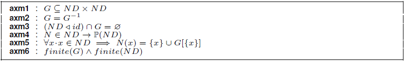
An undirected graph indicates that there is no distinction between two nodes associated with each edge (axm2). A graph is simple if it has zero or one edge between any two nodes and no edge starts and ends at the same node (axm3). The domain restriction "ND ◄ id" is a subset of the relation "id" that contains all the pairs whose first element is in ND. The identity relation id maps every element to itself.
Moreover, we introduce a constant "N" which assigns to each node "x" from the graph the set composed of "x" and its neighbors (axm4, axm5). By means of the axiom axm6, we specify that the set of nodes and edges in the graph are finite.
5.1.2 The context "C1"
It is introduced as an extension of the context "C0" (see Listing 2). We define "cliques" to be a set of all possible cliques in the graph G(axm1). Any pair of nodes can never form a clique, then all cliques contain at least three nodes. We add axm2 and axm3 to specify all possible combinations of maximal and disjoint cliques in the graph G called "clique_combination".

5.1.3 The context "C2"
It extends the context "C1" by adding the labels of nodes into our model. Indeed, we introduce a new set called labels" to represent all possible labels (partition(labels, {Init}, {C}, {I}, {No}, {Alone})). Each node in a particular state is encoded by a specific label which allows nodes to perform an elementary step of computation according to some relabeling rules.
5.2.1 The First Level (Machine M0)
The first machine, called M0, specifies only the goal of the distributed algorithm, but, it does not describe the process of computing the solution. This machine includes only one event Oneshot", depicted in Listing 3, which specifies the result of the algorithm in one step. In other words, there is no protocol, only the formal definition of its intended result. The analogy of someone closing and opening their eyes. To specify this event, we introduce the variable solution" which contains the result of the algorithm execution: a possible combination of maximal and disjoint cliques in the graph G. Formally, "solution" is defined by the invariant inv1: solution ∈ ℙ(ND↔ND). Initially, the variable solution is empty.

In a graph, there are many combinations of maximal cliques. The event Oneshot attributes in a non-deterministic way an element from "clique_combination" to the variable "solution". We prove by refinement that this solution can be calculated.
5.2.2 The Second Level (Machine M1)
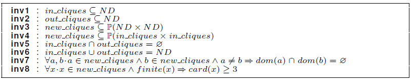
In this machine, we start by introducing details about the maximal cliques algorithm. To do so, we add three variables in the invariant component as shown in Listing 4: "in_cliques" defines the set of nodes which belong to the detected maximal cliques (inv1). "out_cliques" contains the nodes which do not belong to these cliques (inv2). "new_cliques" is the set of edges of the detected maximal cliques (inv3 and inv4). Initially, out_cliques contains all the graph nodes "ND", whereas in_cliques and new_cliques are empty. The definition of these variables requires the addition of new properties:
(inv5) The nodes of in_cliques are different from those of out_cliques.
(inv6) The total of these nodes is equal to the set of nodes ND".
(inv7) There is no intersection between the nodes of the detected cliques.
(inv8) All the detected cliques contain at least three nodes.
At this level, we refine the event Oneshot defined in M0 and we add two new events: Add_in_Clique and Add_out_Clique. Due to lack of space, we detail only the formal specification of the events Oneshot and Add_in_Clique. Event "Add_in_Clique": This new event is added to compute all maximal cliques in the graph G (see Listing 5). It can be triggered if we have a ball "B1" containing at least three nodes (grd3 and grd6). All the nodes of B1 are connected (grd4) and belong to out_cliques, that is to say they have not been assigned to maximal cliques yet (grd1). By means of the grd5, we specify that the ball B1 can not be extended by one or more adjacent nodes. In fact, B1 is not a subset of a larger connected graph. We note “x” the center of the ball B1 (grd2 and grd3). At every computation step, the nodes of the detected ball are eventually added to the set in_cliques (act2) and removed from out_cliques (act1). Moreover, we add the set of ball edges to new_cliques (act3). Event "Oneshot": This event refines the Oneshot presented in M0 to verify that the final value of new_cliques represents the result of the algorithm (see Listing 6). To do so, we reinforce the guard component by specifying that all maximal cliques in the graph G have been detected (grd2). By means of the theorem Th3, we verify that the set new_cliques represents the detected maximal and disjoint cliques. The abstract parameter “c”, defined in M0, is replaced with a concrete value (new_cliques) by means of a witness. In Event-B, a witness is defined as a simple equality predicate involving the abstract parameters.


5.2.3 The Third Level (Machine M2)
The refinement of M1 called M2 introduces more details about the maximal cliques algorithm. In fact, we introduce the variable "Clique" as a function which assigns to each node the set of nodes of its maximal clique (inv1: Clique ∈ ND → ℙ(ND)). Initially, the Clique of each node is empty. To link the states between the machines M1 and M2, we define three gluing invariants:
-
— Each node of in_cliques belongs to a detected maximal clique.
(inv2) ∀x∙x ∈ in_cliques
-
— Each node of out_cliques has not computed its maximal clique yet.
(inv3) ∀x∙x ∈ out_cliques
-
— Each node that has not been assigned to a maximal clique yet belongs to the set out_cliques
(inv4) ∀x∙Clique(x) = Ø
At this refinement level, the events of the previous level still exist but they become more concrete:
— The event "Oneshot" refines the "Oneshot" presented in M1. It uses the concrete variable Clique to specify that each node of the graph has computed the maximal clique to which it belongs.
— We refine the event "Add_in_Clique" of the machine M1 to converge towards the local aspect. The goal of this event is to detect maximal cliques and assign to each node its corresponding clique.
— We refine the event "Add_out_Clique" to give to each node “x” which does not belong to any clique "Clique(x) = {x}".
Due to space limitation, we only detail the specification of the event "Add_in_Clique". The goal of this event is to detect maximal and disjoint cliques and assign to each node its corresponding clique. In fact, we refine the event "Add_in_Clique" of the machine M1 to converge towards the local aspect (see Listing 7).

We reinforce the guard component by using the local variable Clique. The first guard specifies that the center x of the ball B1 and its neighbors from B1 do not belong to any detected clique. The grd5 states that B1 can not be extended by other nodes which have not been assigned to maximal cliques yet. We add the guards grd6 and grd7 to indicate that the intersection of all the elements of N(a), which not belong to maximal cliques, contains at least three nodes.4
We note “a” as each node of the ball B1 . In
the action component, we set the maximal clique of each node of the ball to
"B1" (act1). To do so, we use the overriding
operator "insertar imagen de  ".
".
5.2.4 The Fourth Level (Machine M3)
Once the machine of the third level has been specified and proven, it can be refined to describe the local label modification and encode the relabeling rules proposed in Section 4. In order to reach this goal, we introduce a new variable "State" (inv1:State ∈ ND → labels) which assigns to each node a label from the set labels" that encodes the state of a process. Initially, all the nodes are labeled Init". The addition of the variable "State" involves adding new properties which link the abstract state variables to the concrete ones. We have formalized these properties in form of Event-B invariants:
-
— A node x which has Clique(x) not empty belongs to a maximal clique or it is an isolated node.
(inv2) ∀x•Clique(x) ≠ Ø
-
— A node which has not been assigned to a maximal clique yet is in the initial or the waiting state.
(inv3) ∀x•Clique(x) = Ø
-
— If a node is labeled C, its maximal clique contains itself and a set of its neighbors.
(inv4) ∀x•State(x) = C
-
— Each maximal clique contains one center node labeled C and the other nodes are labeled I.
(inv5) ∀x,y•y ∈ Clique(x)\{x}ɅState(x)=C
-
— If a node y is labeled I, it has a neighboring node which belongs to the same maximal clique and it is the center of this clique.
(inv6) ∀y•State(y) = I
-
— An isolated node does not belong to any maximal clique, then its maximal clique is the identity.
(inv7) ∀x•State(x) = Alone
-
— Each node x labeled C or I belongs to a maximal clique, then it has Clique(x) not empty.
(inv8) ∀x•State(x) ∈ {C, I}
-
— Each node in the initial or the waiting state has not been assigned to a maximal clique yet.
(inv9) ∀x•State(x) ∈ {No, Init}
At this level, we refine the event "Oneshot" and we specify the three relabeling rules of the algorithm:
— The event "Oneshot" verifies that, at the end of the algorithm execution, no node is in the initial or the waiting sate. The set of maximal cliques correspond to nodes labeled C" and its neighbors labeled I".
— The relabeling rule R1 is specified by an event called "Rule1" which refines the event "Add_n_Clique" defined in M2.
— The event Rule2" is introduced to specify the rule R2.
— The event "Rule3" specifies the rule R3 and refines the event "Add_out_Clique" of the machine M2.
5.3 Overview of Proof Obligations
We present in Fig. 2 the proof statistics for the development of our algorithm using the RODIN platform. These statistics are a measure of the development complexity. We distinguish the proof obligations (POs) discharged automatically by RODIN and those that are interactively proved. The algorithm development results in 188 POs, in which 86 (46%) POs are automatically proved, and 102 (54%) are interactively proved using the RODIN prover. Many POs are generated in Event-B models due to the introduction of local information. In order to ensure the correctness of the machines, we have established various invariants in stepwise refinement.

6 Conclusion and Future Work
In this paper, we have addressed the problem of enumerating maximal cliques in a graph.
Unlike the existing works, our solution is based on a distributed algorithm encoded by the local computation model. This model provides an abstraction of distributed computations, which can be expressed by the Event-B method. To do so, we have proposed three relabeling rules which represent the local behaviour of processors ensuring the detection of maximal cliques.
Moreover, we have specified our algorithm based on a stepwise refinement strategy to build a correct solution. The proof obligations discharged either automatically or interactively is a measure of the development complexity.
We intend in the future to extend our solution to construct maximum cliques which represent the clique that contains the largest number of nodes in the whole graph. In addition, it is interesting to verify the correctness of temporal properties such as liveness properties that can not be verified using invariants.


