


 text new page (beta)
 English (pdf)
 Article in xml format
 Article references
 Send this article by e-mail
 Cited by SciELO
  Similars in
SciELO
Similars in
SciELO 
 Permalink
1 Introduction
The use of halfband filters (HBF) and digital differentiators (DD) is key to perform several signal processing tasks. For example, HBF are used to perform the decimation and interpolation of signals [33, 36]; while DD are typically used when information about signal rate of change is required [21, 18].
Furthermore, maximally flat halfband filters (MFHB) and maximally lineal differentiators (MLD) have been widely studied [27, 39, 12, 29, 4, 20]. They present the maximum flatness/linearity of its frequency response around a particular frequency called flatness center.
In general, maximally flat (MAXFLAT) filters are of particular interest in applications that require smooth frequency responses or high attenuation in the stop-band [2, 24]. They are ripple-free and are of particular importance for the analysis of polynomial signals. Several designs have been proposed for the design of MAXFLAT filters since they emerged in [5]. They include FIR linear phase filters [26, 19], generalized filters [28, 40] and fractional delay filters [13, 38]. The main drawback of using MAXFLAT filters is the width of its transition band, which is superior to that presented in other designs which allow ripple, e.g., [22]. Additionally, in a MAXFLAT design, the bandwidth can only be decreased by increasing the filter length.
Several methodologies have been proposed to decrease the transition band in MAXFLAT designs preserving as much as possible the flatness of the frequency response. Some algorithms use a frequency different from zero as the flatness center to produce narrower filters [14, 15] while others increase the design flexibility by not taking into account all the MAXFLAT constraints [10, 31].
Recently, [7] presents a method for impose a prescribed cutoff frequency in a MAXFLAT design, but it was not applied to the design of halfband filters. With respect to MFHB filters, [8] presented a method for the design of MFHB filters with narrow transition bands. This method consists in convert the MLD presented in [11] into a MFHB filter using the transformation method described in [23]. The filters obtained in [8] are designed with MAXFLAT constraints around ω = π/4 rad. They have narrower transition bands than conventional methods. On the other hand, they are not ripple free and present the maximum ripple at ω = 0.
The main purpose of this work is to obtain type 1 FIR flat HBF with linear phase and narrow transition bands, persevering as far as possible the passband flatness. The filters will be obtained by imposing a set of MAXFLAT constraints around a variable flatness center and the formulation of a convex quadratic programming problem (CQP) with inequality constraints. The application of this procedure for the design of type 4 FIR differentiators is also shown. The main differences with respect to previous work based on linear programming or CQP filter design [17, 6, 30, 16, 1, 31, 20, 34] are: (a) Design flexibility is enhanced due to a larger number of parameters. (b) It is possible to increase the accuracy of the frequency response at a particular frequency by introducing a weighting matrix. (c) The same algorithm can be used (with minor modifications) to design halfband filters or differentiators. We used QP instead of the more general convex optimization [35, 3] in order to obtain a straightforward formulation. Despite the fact that a simple and well-known optimization technique was used, it will be shown that the proposed method generates filters with better frequency characteristics than other designs which are also based on subsets of MAXFLAT constraints.
The rest of this document is structured as follows: As a brief summary Section 2 presents the conventional design of MFHB and MLD. Subsequently, in Sections 3 and 4 are presented the proposed designs for type 1 HBF and type 4 DD. Finally two design examples are shown in Section 5.
2 Summary on MAXFLAT Filter Design
In what follows we present the classical design of HBF and DD using MAXFLAT constraints. We consider type I FIR filters for the HBF and type IV FIR filters for the DD. Form more information, please refer to [32, 9].
2.1 Type I FIR MAXFLAT Halfband Filters
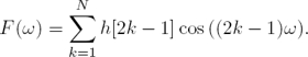
In the general case, a low-pass type I Halfband FIR filter of length 4N − 1 has a frequency response given by:
 (1)
(1)
with
 (2)
(2)
The function H(ω) is such that H(ω) + H(ω − π) = 1. The impulse response h[k] of H(ω) depends only on the odd coefficients, as the even coefficients of h[k] are fixed and given by:
 (3)
(3)
In order to simplify the nomenclature, from here odd coefficients of h[k] are represented by f[k] = h[2k − 1].
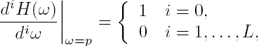
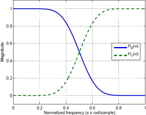
An example of the aspect of the frequency response of a low-pass H(ω) and a high-pass H(ω − π) HBF is given in the Fig. 1. The filters presented in Fig. 1 are MAXFLAT, i.e. their passband and stop-band fulfill a set of maximally flat constraints. Maximally flat constraints eliminate the maximum amount of derivates of H(ω) around a particular frequency ω = p called the flatness center:
 (4)
(4)
as we will consider halfband filters, eq. (4) also implies
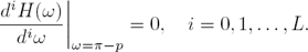 (5)
(5)
The conventional design of MFHB filters involves solving a system of (N × N) linear equations derived from the MAXFLAT constraints (4). This set is obtained by applying the constraints (4) to (1) with L = N − 1, and is given by
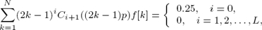 (6)
(6)
where Cn(ω) = cos(ω) for odd values of n and Cn(ω) = sin(ω) for even values.
Usually the flatness center is p = 0. In this case all the odd order derivates in (6) are canceled automatically due to symmetry of H(ω). Then L = 2(N −1) is chosen to obtain a (N × N) system of linear equations similar to (6), and given by
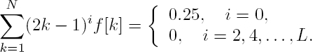 (7)
(7)
Note that (7) is a Vandermonde system; then Vandermonde determinant can be used to solve (7) and find the following closed forms for the impulse response coefficients
 (8)
(8)
Fig. 1 shows the frequency response of a bank of MFHB filters designed through this approach. The filters presented in Fig. 1 were obtained using (8) with N = 5.
2.2 Type IV FIR Maximally Linear Digital Differentiators
A type 4 maximally linear (MAXLIN) differentiator of length 2N has a frequency response given by
 (9)
(9)
As for the MAXFLAT halfband case, from here we will denote f[k] = h[k − 1/2] as the impulse response coefficients. In this work type IV filters were preferred over type III as type IV filters are not restricted to H(ω) = 0 at ω = π. Then they are more appropriate to design full-band DDs.
If L MAXLIN constraints are imposed over H(ω) at ω = p
 (10)
(10)
Then, the following linear system of equations:
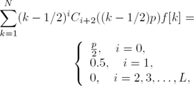 (11)
(11)
is obtained.
Considering p = 0, and L = 2N − 1, (11) can be simplified to the (N × N) Vandermonde system:
 (12)
(12)
with the solution expressed by
 (13)
(13)
3 Proposed Design for Type I FIR Half-band Filters
Next, we present the proposed methodology for the design of type I FIR flat halfband filters with narrow transition bands by means of quadratic programming optimization.
We consider L ≤ N − 1 MAXFLAT constraints around the flatness center ω = p, where  . An overdetermined system of linear equations
 (14)
(14)
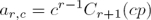
is imposed over f[k] in order to meet (4), where the r-th element of the c-th column of A ∈ ℝN×(L+1) is
 (15)
(15)
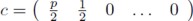
where c ∈ ℝL+1 and f ∈ ℝN are given by:
 (16)
(16)
and
 (17)
(17)
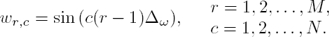
A vector with M samples of H(ω) uniformly distributed over  can be obtained using H = 0.5u + W ho, where u ∈ RM represents an unitary vector, and W ∈ ℂM×N has elements given by:
 (18)
(18)
with ∆ω = π/2M.
On the other hand, If M samples of an uniform sampled version of a desired frequency response Hd(ω) over , are defined as a vector Hd; then, the design of the halfband filter can be stated as the optimization problem: Find the set of coefficients f that minimize the energy of the difference between the ideal Hd and the proposed H = 0.5u + W f frequency responses. The problem can be stated as the following quadratic programming optimization problem with equality constraints.
Find the best f for
 (19a)
(19a)
 (19b)
(19b)
where Fd = Hd − 0.5u, R ∈ ℜM×M is a weighting matrix, and the pair (R, W ) is restricted to W T RW > 0 to ensure the convexity of the problem.
The solution of the QP problem presented in (19) is
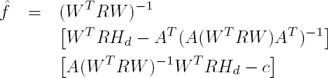 (20)
(20)
and its derivation through Lagrange multipliers is shown in the appendix.
3.1 Selection of the Weighting Matrix R
The matrix R in (19) and (20) could be used to weight certain frequencies. It is possible to use this matrix to highlight frequencies which are located far from the flatness center p. The frequencies close to ω = p could receive less weight through R because the flat constraints (4) ensure a good approximation of H(ω) to Hd(ω) around ω = p and ω = π − p.
In Fig. 2 are shown the results obtained through the use of (20), with N = 10, L = 3, p = 0 and R being a diagonal matrix, with the elements of its diagonal given by the Kaiser window. Specifically, the k-th element of the diagonal of R is given by:
 (21)
(21)
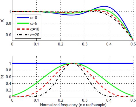
Fig. 2 The parameter R and its effect over the frequency response. (a) Frequency response and (b) The weighting function used
with I0 being the zeroth order modified Bessel function of the first kind, α a non-negative real number that define the shape of the window, and δr ⋘ 1 being an arbitrary positive real number which ensures the existence of R−1. The effect of R over H(ω) is shown in Fig. 2 for different values of α.
Note from Fig. 2 that, for the window used, a greater α gives more weight to the frequencies near ω = π/4 and located outside the flat bands. Then, a better approximation to Hd(ω) around ω = π/4 is obtained.
3.2 Side Lobe Control
The designed filters are susceptible to the presence of ripple in their bands as the design does not take into account the maximum number of flat constraints. If it is desired to minimize this ripple in certain frequency band ω ∈ [0, ωp], it is possible to add the linear box constraint
 (22)
(22)
on F (ω), where δl represents the desired level of ripple in the band ω ∈ [0, ωp] and Wpf the frequency response of the filter in the same band. The matrix Wp represents a subset of the rows of the matrix W related to the frequencies within the band ω ∈ [0, ωp]. The design problem is then given by the following quadratic programming problem with inequality constraints:
Find f for
(23a)
 (23b)
(23b)
 (23c)
(23c)
The solution of (23) can be obtained using a variety of iterative algorithms found in the literature (e.g. Interior point [25, page 537] or active set [37, page 455]). In addition, there are numerous software packets available to solve such problems (e.g. Optimization toolbox for MATLAB, IBM ILOG CPLEX Optimization Studio, Gurobi, etc.).
Design approaches similar to that proposed in (23) can be consulted in [17, 6, 30, 31]. In contrast to these, the main differences of the proposed method are: Design flexibility is increased due to a larger number of design parameters (N, L, P , R, Hd, δl, ωp). Furthermore, using a criterion in the sense of weighted least squares enables a particular emphasis on specific frequencies. We also take into account inequality constraints (23c) to constrain the ripple on the passband and stop-band. Finally, note that as the desired frequency response Hd is not fixed to the ideal frequency response, any desired Hd can be used.
4 Proposed Design for Type IV FIR Digital Differentiators
The QP optimization problems shown in (19) and (23) can be used to design a type 4 DD instead of a type I HBF if the elements in (19) and (23) are redefined as follows:
— Fd ∈ RM represents M uniformly distributed samples of the DD frequency response in ω ∈ [0, π]. And, for the ideal case, it has elements fr given by:
 (24)
(24)
with ∆ω = π/M.
— W ∈ RM×N represents a linear transformation from time to frequency domain and its elements are given by:
 (25)
(25)
— A ∈ RN×(L+1) and c ∈ RL+1 represent the flat constraints over the DD frequency response. A has elements:
 (26)
(26)
for p ≠ 0, or
 (27)
(27)
for p = 0.
Where c is given by
 (28)
(28)
for p ≠ 0, or
 (29)
(29)
for p = 0.
5 Design Examples
Next, we present two design examples. The first of them deals with the design of a flat HBF with narrow transition bands, while the second one shows the design of a full-band DD with a flatness band around ω = 0. In both cases, results obtained are compared with different conventional designs.
5.1 Example 1 - Halfband Filter Design
In this example we design a HBF subject to a maximum ripple of δr = 0.005 in the band ω ∈ [0, 0.32π]. For this case, we use a length of 13 samples (N = 5). The rest of the used parameters are: (L = 2, p = 0, α = 0, Hd = u). Under these conditions, the QP problem expressed in (23) was solved using the active set method. Specifically, we use the quadprog function of the Matlab optimization toolbox. It takes 9 iterations to find the local minimum solution for the algorithm; which, in view of the fact that the optimization problem is convex, is also a global solution.
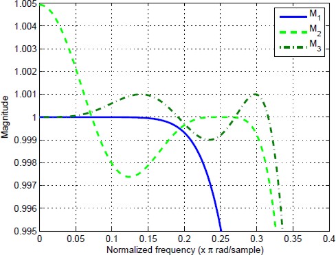
Results obtained for the conventional MFHB method (obtained from eq. (8) and labeled M1), the proposed method in [8] (labeled as M2) and the proposed method of this work (solution of (23) and labeled as M3) are shown in the Table 1 and the Fig. 3. The Fig. 4 shows a zoom to the ripple in the passband of the filter. Note from Figs. 3 and 4 that the bandpass of the filter M3 was increased with respect to the classical design M1 and it is similar to M2. Furthermore, note from Fig. 4 that M3 satisfy the design bounds; the ripple of M3 was decreased by a factor of 5 with respect to the one obtained using M2. In addition, the ripple in M3 can be decreased if a lower δr is imposed and bandwidth is reduced.
Table 1 Impulse responses for the different HBF used. Where M1 stands for the conventional MFHB method (obtained from eq. (8), M2 for the filter obtained by applying the method shown in [8], and M3 for the approach of this work (solution of eq. (23))
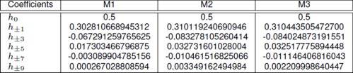
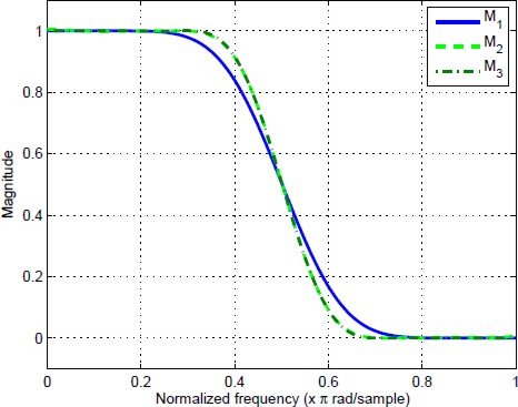
Fig. 3 Frequency responses of the halfband filters obtained from eq. (8) (labeled as M1), the design presented in [8] (labeled as M2) and the proposed method (labeled as M3)
5.1.1 Designs for Different Values of N
We also compare M1, M2 and M3 for different lengths. The filters obtained with N = {5, 10, 15, 20, 25, 30} for each case (M1, M2, or M3) are shown in Fig. 5. For each filter in the M3 group we use (L = N − 3, p = π/8, α = 0, Hd = u, δr = 1 × 10⁻⁴).

Fig. 5 Frequency responses of halfband filters obtained for different lengths from a) M1, b) M2 and c) M3. The length of each filter is related to N by the relation 4N − 1
We compare the performance of each group using the maximum ripple and the 3-dB bandwidth, this comparison is shown in Fig. 6. Note from Figs. 5 and 6.b that, under the same filter length, the bandwidth of the M3 group is in general bigger (with exception of N=5) that the one of the groups M1 and M2.

Fig. 6 Characteristics of the frequency responses of M1, M2 and M3 for different lengths. a) Maximum ripple in the pass-band and b) 3-db Bandwidth in normalized frequency. The maximum ripple of M1 is omitted because it is ripple free. The length of each filter is is related to N by the relation 4N − 1
Also note form Fig. 6.a that the maximum ripple of M3 is always lower than that of M2 and within the imposed bound.
5.2 Example 2 - Full-band Digital Differentiator Design
We present the design of one full-band DD of a length equal to 34 samples (N = 17). The design was made through the solution of (23), using the following modified constraint (23c):
 (30)
(30)
with δl = π/100.
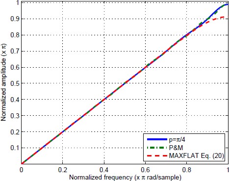
The Fig. 7.a shows the frequency response obtained for p = π/4 and L = 2; the error between the desired frequency response and the one obtained is shown in Fig. 7.b. Note from Fig. 7.b that the frequency response obtained meets the imposed constraints.
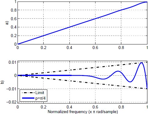
Fig. 7 Results obtained for the design of a FIR type 4 full-band differentiator. (a) Obtained frequency response, (b) Error obtained with respect to Hd
The absolute value of the error |H(ω)−Hd(ω)| is shown in Fig. 8 for different values of p. Note that in all the cases, the error is such that (30) holds. In addition; it is possible to note from Fig. 8 that the bandwidth increases at higher p.
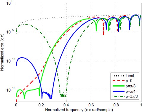
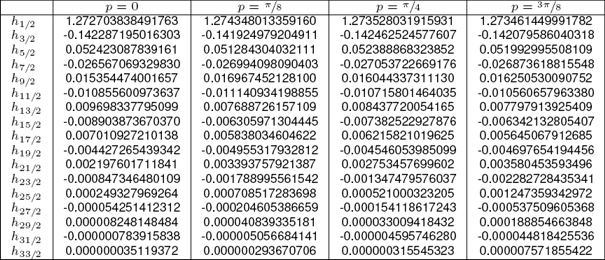
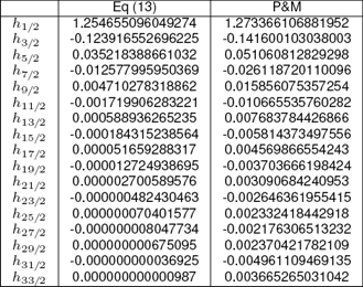
The comparison of the DD obtained with a DD designed from Parks & Mcmillan algorithm and a MAXLIN DD designed from (13) is presented in Figs. 9 and 10. All of the differentiators used have the same length, their impulse responses are shown in Table 3.
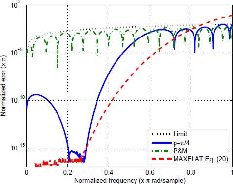
Note from Fig. 10 that we obtain a trade-off between the equiripable and the MAXLIN designs. The magnitude of the error in the proposed design is lower than that obtained by the equiripable differentiator at low frequencies around the flatness center.
Also, the magnitude of the error for the proposed design is lower than the one presented by the classical MAXLIN design at high frequencies due to the imposed bounds. Finally, the impulse responses related to the filters used in this section are shown in Tables 2 and 3.
6 Conclusions
A design method for flat halfband filters with narrow bands via constrained optimization was presented. This method is based on the generation of one or more degrees of freedom in a MAXFLAT design. The reduced set of MAXFLAT constraints is added as a set of equality constraints to the QP problem. The ripple in the passband is bounded by linear inequality constraints added to the optimization problem. The proposed methodology was applied to the design of type I FIR halfband filters and full-band type IV FIR differentiators.
With respect to the designed differentiators, only full-band differentiators were considered but in general the proposed approach can be used to design band-pass type IV and type III differentiators with some minor modifications. Design examples were presented to demonstrate the effectiveness of the proposed method to design halfband filters and full-band differentiators.
As it can be seen in the results section, it was shown that the proposed method has the advantage of producing flat halfband filters with narrower transition bands in comparison with classical MAXFLAT designs. Finally, it is important to highlight that as this method is based on quadratic programming it has some inherent limitations. For example, there are not closed expressions for the coefficients of the impulse response; and if design specifications are more demanding the feasible space will be reduced.

