


Services on Demand
Journal
Article
 English (pdf)
 Article in xml format
 Article references
 Send this article by e-mail
Indicators
-
 Cited by SciELO
 -
 Access statistics
Related links
-
 Similars in
SciELO
Similars in
SciELO
Share

 Permalink
Revista de la Sociedad Química de México
Print version ISSN 0583-7693
Rev. Soc. Quím. Méx vol.46 n.1 Ciudad de México Jan./Mar. 2002
Investigación
Kinetic modeling of vacuum gas oil catalytic cracking
Jorge Ancheyta1* and Rogelio Sotelo2
1 Instituto Mexicano del Petróleo, Eje Central Lázaro Cárdenas 152, México 07730, D.F. Fax: 3003-8429. E-mail: jancheyt@imp.mx
2 Instituto Politécnico Nacional, Escuela Superior de Ingeniería Química e Industrias Extractivas, México 07738, D.F.
Recibido el 9 de agosto del 2001.
Aceptado el 23 de enero del 2002.
Abstract
A new kinetic model for catalytic cracking of vacuum gas oil is presented. The proposed model is based on lumping technique and considers the most important products in the FCC process: (1) gasoline (C5-493 K), (2) C4's (butane, i-butane and butenes), (3) C3's (propane and propylene), (4) dry gas (H2, C1-C2), (5) coke and (6) unconverted VGO (decanted and light cycle oils). A vacuum gas oil and an equilibrium catalyst recovered from a commercial FCC unit were employed to evaluate the kinetic and deactivation constants by using experimental information obtained in a microactivity plant. Good predictions of product yields with average absolute deviation less than 5 % with respect to experimental information were obtained.
Keywords: Catalytic cracking, kinetic model.
Resumen
Se presenta un modelo cinético para la desintegración catalítica de gasóleos. El modelo propuesto se basa en la técnica de agrupamiento por pseudocomponentes y considera los productos más importantes del proceso FCC: (1) gasolina (C5-493 K), (2) C4's (butano, i-butano y butenos), (3) C3's (propano y propileno), (4) gas seco (H2, C1-C2), (5) coque y (6) gasóleo no convertido (aceites decantado y cíclico ligero). El gasóleo de vacío y el catalizador de equilibrio se recuperaron de una unidad comercial de FCC, y ambas muestras se utilizaron para evaluar las constantes cinéticas y de desactivación usando información experimental obtenida en una planta de microactividad. La predicción de los rendimientos de productos fue aceptable con desviaciones absolutas en promedio menores a 5 % con respecto a la información experimental.
Palabras clave: Desintegración catalítica, modelo cinético.
Introduction
Fluid Catalytic Cracking, better known as FCC, is one of the most important and complex processes in petroleum refining which is used to upgrade heavy petroleum gas oils into gasoline, diesel fuel, light olefins and other valuable products. Since its first commercial advent in 1942, various papers have been written dealing with different aspects of this technology [1, 2].
The FCC process comprises mainly of two parts: (1) a reactor, where high molecular weight hydrocarbons come in contact with the catalyst and crack to lower molecular weight products with simultaneous deposition of coke on the catalyst, and (2) a regenerator, where the coke on the catalyst is burnt with air and the catalyst is returned to the reactor [3].
The FCC process can be applied to many different types of feedstocks. The Fluid Catalytic Cracking feeds, mainly integrated by vacuum gas oils (VGO) and heavy atmospheric gas oil, are mixtures of innumerable individual molecular hydrocarbons species containing 20 to 50 carbons that exhibit a wide range of cracking rates, including paraffins, isoparaffins, naphthenes, aromatics and asphaltenes. A typical gas oil also contains significant quantities of multiringed molecules containing heteroatoms, such as nitrogen, sulfur and metals [4].
In developing of kinetic models for the catalytic cracking of VGO the usual approach has been to use lumping techniques. This is due to the large number of individual species present in the feedstock.
One of the first studies about FCC kinetic modeling based on lumping technique was the three-lump kinetic scheme [5], which consist of a VGO lump, a gasoline lump (C5 to 493 K) and a gases lump (C4 and lighter) plus coke. In this model the gasoline fraction is the most profitable component of the cracked products. The VGO lump can crack either to form gasoline or to form gases plus coke. The gasoline formed may also undergo further cracking to gases plus coke.
Other kinetic models based on lumping have been reported in the literature [6-14]. Yen et al. [7] and Lee et al. [8] expanded the 3-lump model into a 4-lump kinetic model by separating the gases and the coke lumps. Takatsuka et al. [9] presented a 6-lump model for residual oil cracking. This model was adapted by Corella et al. [10] for VGO cracking, which considers the VGO, heavy and light cycle oils, gasoline, gases and coke as lumps.
A 10-lump model identifies lumps whose kinetic constants are independent of feedstock composition [6]. This model is an extension of the 3-lump model. The difference is that the feedstock lump was divided into paraffins, naphthenes, aromatic rings, and aromatic substituent groups in light (473 to 618 K) and heavy oil (618 K+) fractions. The gasoline and gases plus coke lumps remain the same as in the 3-lump model. Similar models with 5, 7 and 8 lumps have also been reported in the literature [11-13], which are essentially simplified versions of the 10-lump model. Table 1 shows the evolution of the most important lumped kinetic models for catalytic cracking process over the last 30 years.
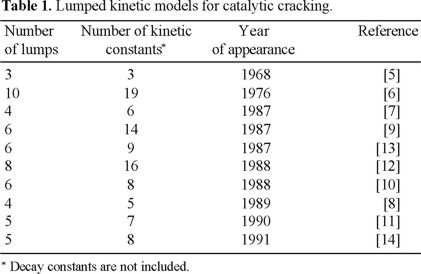
The number of lumps of the reported models for catalytic cracking reactions has been increased to obtain a more detailed prediction of product distribution, however, most of them involve gaseous products (C3's, C4's and dry gas) as a lump and in some cases these gases are also lumped together with the coke yield.
In order to predict individually the key FCC products in this work we present a new kinetic model for catalytic cracking which takes into account C3's, C4's, dry gas and coke yields separately from the unconverted VGO and gasoline lumps.
The kinetic model
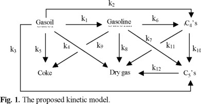
The kinetic model proposed in this work has 6 lumps and is shown in figure 1. It takes into account the most important products in the Fluid Catalytic Cracking process: (1) gasoline (C5-493 K), (2) C3's (propane and propylene), (3) C4's (butane, i-butane and butenes), (4) dry gas (H2, C1-C2), (5) coke and (6) unconverted VGO (decanted and light cycle oils). This model has twelve kinetic constants and one for catalyst deactivation to be estimated.
The kinetics for VGO cracking has been found experimentally to follow a reaction order close to two. Pure hydrocarbons are know to crack according to a first reaction order, by this reason the gasoline, being a mixture of hydrocarbons having a limited range of boiling points, C3's and C4's lumps are assumed to crack with an order of one [15].
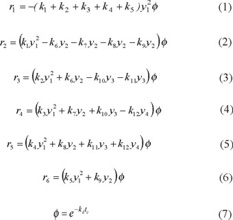
Based on these considerations, the following kinetic expressions were formulated as a function of product yields, deactivation function and kinetic constants. The exponential law was assumed for catalyst decay. A non-selective deactivation model was used in this study in order to simplify the overall kinetic model and parameter estimation.
Experimental
Feedstock and catalyst
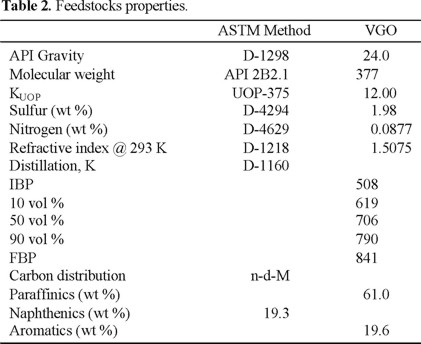
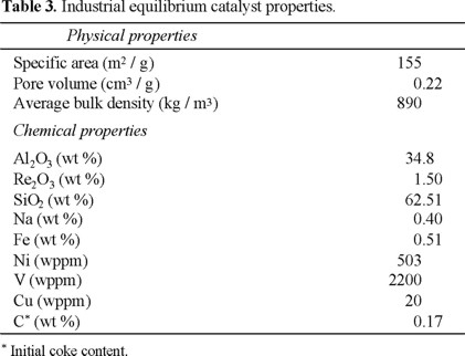
A typical vacuum gas oil and a commercial equilibrium catalyst taken directly from the circulating inventory of an industrial catalytic cracking plant were used in this study. The equilibrium catalyst was previously decoked at 853 K during 3 h.
Properties of feedstock and catalyst are reported in Tables 2 and 3 respectively.
Experimental runs
The MAT (Microactivity Test) technique, a normalized ASTM procedure for a standard feedstock which allows change easily the reactions conditions, was used for kinetic measurements (Fig. 2).
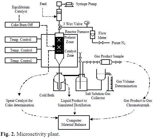
The fixed-bed tubular plug flow reactor, reactor oven, oil injection and products recovery system is described by ASTM D3907-92 method.
Experimental runs were performed at reaction temperature of 773 K and space-velocities in the range of 6-48 h-1.
In each experiment, a new portion of equilibrium catalyst was used. Varying the time of injection, and consequently the gas oil rate, establishes a range of catalyst time-on-stream values to provide different space-velocities.
Preheated feed (0.8 ± 0.005 g) is injected using a syringe bomb through a 4 g bed of catalyst maintained at the required cracking temperature.
Liquid product from the reactor is collected in an ice-cooled receiver. The uncondensed gaseous products pass through the liquid products and are collected in a brine solution. The gas volume is determined by displacement of the brine volume.
Analysis of products
Gaseous products (H2 and C1-C6) were analyzed isothermally at 323 K using an HP 5890 Series 2 GC equipped with two thermal conductivity detectors (TCD).
Liquid products were analyzed by the chromatographic simulated distillation procedure described by ASTM D-2887 method.
The carbon content of the catalyst was determined after reaction by combustion using an infrared analysis of the produced CO2 (LECO VIA-510).
The fractions of gasoline and unconverted VGO were defined by the cut points at C5-493 K and 493 K+, respectively.
The product yields were calculated as weight percent of the reactant. Mass balances were performed for each run in the range 100 ± 5 % and the conversion in weight percent was evaluated as the sum of C5 + gasoline, propanes, butanes, dry gas and coke, representing 100 % minus unconverted gas oil yield.
Results and discussion
MAT experiments
Figure 3 presents the experimental data for gasoline, C4's, C3's, dry gas, coke and unconverted VGO yields at 773 K as a function of space velocity (WHSV).
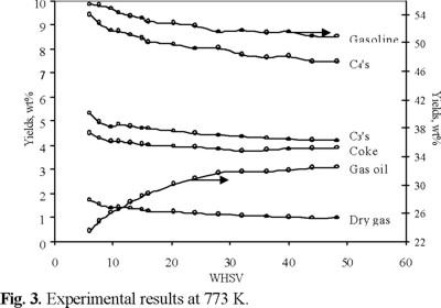
It can be seen from this figure that unconverted gas oil and gasoline yields were obtained in the range of 23.5-32.5 wt % (67.5-76.5 wt % conversion) and 50.9-55.5 wt % respectively, which are similar to those reported in commercial units [2].
When VGO is catalytically cracked many of the primary products undergo secondary reactions. The gasoline fraction (C5-493 K) reach a maximum yield with conversion and then undergoes further cracking usually referred to as over-cracking. From figure 3 can be seen that gasoline yield is always increasing as the WHSV decreases, it means that the reaction is below the over-cracking. The smaller WHSV increases the contact time and favors gas oil conversion and cracking products yields.
Kinetic modeling
The kinetic model was incorporated into an isothermal plug flow reactor model. Axial dispersion and external and internal diffusion in the reactor were neglected.
The mass balance equations for each lump were used to evaluate the product yields from a set of kinetic constants.
The following objective function, based on the sum of square errors between experimental and calculated yields, was applied to find the best set of kinetic parameters:
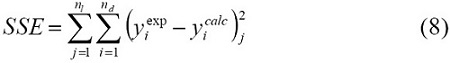
This objective function was solved using the least squares criterion with a non-linear regression procedure based on Marquardt's algorithm [16].
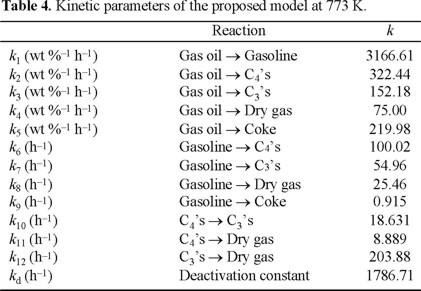
Table 4 shows the estimated kinetic constants at 773 K for each reaction lump involved. A comparison of the values of these kinetic constants with other values reported in the literature is difficult. The reasons for this are that in the literature all the gases and coke yields are referred as a lump (gases plus coke) and most of the models do not separate the gases lump in C3's, C4's and dry gas. Despite this, the following ratios of the kinetic constants can be compared:
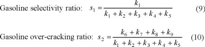
s1 and s2 values were 0.8044 and 0.0461, and those reported in the literature are in the range 0.63-0.90 and 0-0.086, respectively.
It can be observed that our results are in full accordance with the range of the ratios of kinetic constants reported in the literature [6-14].
With the values of the kinetic constants reported in Table 4, equations (1)-(7) were solved numerically using a fourth order Runge-Kutta method with the following boundary condition: y1 = 1, y2 = y3 = y4 = y5 = y6 =0 at conversion (x)=0.
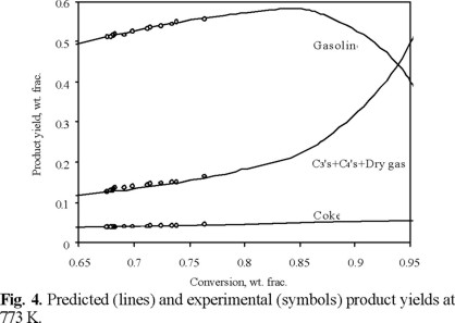
Figure 4 shows a comparison of the predicted and experimental yields for gasoline, gases (C4's, C3's and dry gas) and coke versus conversion. It can be seen that the kinetic parameters obtained with the proposed model predicted very well the MAT product yields at 773 K with average deviations less than 5 %.
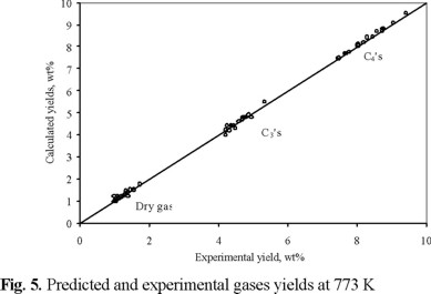
Experimental and calculated C4's, C3's and dry gas yields are also compared in figure 5. The slope of the straight line between these values was very close to unity (1.0039) with a correlation coefficient of 0.99.
The conversion range with the most significant differences in gasoline yields is from 65 to 90 wt %, which is in the range of industrial FCC units.
Gasoline is an intermediate product in the reaction scheme shown in figure 1 and its kinetic constants are very important, since gasoline fraction is the most profitable product of the FCC products.
The kinetic constants for gasoline cracking (k6, k7, k8 and k9) are considerably smaller than the rate constant for gasoline formation (k1) (100.02, 54.96, 25.46 and 0.915 versus 3166.61). It confirms, first, that the MAT experiments were conducted below over-cracking region, and secondly, that gasoline gives mainly C4's and C3's, while the coke is produced mainly by the cracking of VGO, since the kinetic constant (k9) for the reaction Gasoline → Coke was many orders of magnitude smaller than for the others.
The value of the maximum gasoline yield predicted with the proposed model is about 85 wt % which agrees with those reported industrially [2]. This maximum occurs near the small values of WHSV (< 4) as can be observed in figure 3.
Advantages and limitations of the proposed model
The catalytic cracking of VGO results in a broad spectrum of products, ranging from hydrogen and methane to heavy polymeric material adhering to the catalyst as coke. By this reason, lumps model are commonly used to describe the kinetics of this process in order to reduce the broad spectrum of catalytic cracking charge stocks and products into a few pseudocomponents.
As it was mentioned before, various lump models have been proposed in the literature for FCC process [6-14]. The main disadvantage of these models is that most of them consider the gaseous products as a lump.
The advantage of the model proposed in the present work is that it can predict separately the most important product of the FCC process (gasoline, C4's, C3's, dry gas and coke).
The problems with the lump models is that the relative concentrations of the species making up individual kinetic lumps can change as the reaction proceeds and thus these models cannot be extrapolated to new conditions or feed-stocks and they are specific for the feedstock, catalysts and operating conditions used to obtain the kinetic information.
However, even though there are in the literature more realistic kinetic models that describe the cracking reactions using more detailed schemes, lump models are frequently used for modeling and simulation purposes because they are still capable to illustrate the interactions between the process variables and the reactions rate and catalyst decay velocity.
In the case of the proposed model, it is possible to predict gasoline, C4's and C3's selectivities that represent the most significant contributions to the profitability of a catalytic cracking unit. In addition, a simplified reaction scheme can perfectly illustrate the capabilities of computational techniques in modeling complex process operations, within acceptable computational costs.
Conclusions
Experimental data about the catalytic cracking of vacuum gas oil obtained in a microactivity reactor (MAT) at reaction temperature of 773 K and WHSV between 6-48 h-1 using a commercial equilibrium catalyst were utilized to evaluate the kinetic parameters of a new lump kinetic model for catalytic cracking process.
Ratios of the obtained kinetic constants with respect to the global gas oil cracking kinetic constant agreed with those reported in the literature.
The kinetic parameters have been used to predict gasoline, C3's, C4's, dry gas, coke and unconverted VGO yields. Good predictions of these product yields were obtained with average absolute deviation less than 5% with respect to experimental information.
Acknowledgements
The authors wish to thank Instituto Mexicano del Petróleo for its financial support. R. Sotelo also thanks CONACyT for financial support.
References
1. Venuto, P.; Habib, E. Cat. Rev.-Sci. 1978, 18, 1-150. [ Links ]
2. Sadeghbeigi, R. Fluid Catalytic Cracking Handbook: Design, Operation and Troubleshooting of FCC Facilities. Gulf Publishing Co., Houston, TX, 1995. [ Links ]
3. Moharir, A. S.; Sarae, S. K. Chem. Age of India 1984, 35, 433-440. [ Links ]
4. Harding, R. H.; Zhao, X.; Kuangnan, Q.; Rajagopalan, K.; Cheng, W. Ind. Eng. Chem. Res. 1996, 35, 2561-2569. [ Links ]
5. Weekman, V. M. Ind. Eng. Chem. Prod. Res. Dev. 1968, 7, 90-95. [ Links ]
6. Jacob, S. M.; Gross, B.; Voltz, S. E.; Weekman, V.W. AIChE J. 1976, 22, 701-713. [ Links ]
7. Yen, L. C.; Wrench, R. E.; Ong, A. S. in: Katalistics' 8th Annual Fluid Cat Cracking Symp. Budapest, Hungría. 1987, 7:1-7:7. [ Links ]
8. Lee, L. S.; Chen, Y.W.; Huang, T.N.; Pan, W.Y. Can. J. Chem. Eng. 1989, 67, 615-619. [ Links ]
9. Takatsuka, T.; Sato, S.; Morimoto, Y.; Hashimoto, H. Int. Chem. Eng. 1987, 27, 107-116. [ Links ]
10. Corella, J.; Provost, M.; Espinosa, A.; Gutierrez-Morales, F. in: Proc. of the XI Iberoamerican Symp. on Cat., México, 1988, 415-421. [ Links ]
11. Larocca, M.; Ng, S. de Lasa, H.I. Ind. Eng. Chem. Res. 1990, 29, 171-180. [ Links ]
12. Kraemer, D. W., de Lasa, H.I. Ind. Eng. Chem. Res. 1988, 27, 2002-2008. [ Links ]
13. Coxson, P.G.; Bischoff, K.B. Ind. Eng. Chem. Res. 1987, 26, 1239-1248. [ Links ]
14. Corella, J.; Frances, E. in: Fluid Catalytic Cracking II, ACS Symposium Series, Vol. 452, 1991, 165-182. [ Links ]
15. Blanding, F. H. Ind. Eng. Chem. 1953, 45, 1186-1197. [ Links ]
16. Marquardt, D. W. J. Soc. Ind. Appl. Math. 1963, 2, 431-441. [ Links ]

