


 nueva página del texto (beta)
 Inglés (pdf)
 Artículo en XML
 Referencias del artículo
 Enviar artículo por email
 Citado por SciELO
  Similares en
SciELO
Similares en
SciELO 
 Permalink
Introduction
Fracture of rotary instruments of nickel and titanium root canal files (NiTi) can be a huge problem during the treatment of dental root canal, since it can compromise the prognosis when it is not possible to remove the fragment. Cyclic fatigue and torsional fatigue play important roles to induce the fracture of such rotating instruments; these physical phenomena can interact so that a combined process of both forces can enhance the risk to fracture1-3.
Recently, Y. Shen, et al., studied the effect of several degrees of cyclic fatigue on torsional fracture and torsional preload on K3 and K3XF heat treated instruments. The fatigue behavior of the NiTi instruments was tested with the rotary instruments immersed in an aqueous medium. Therefore, to determine the resistance to cyclic fatigue, new instruments 25/04 K3XF and K3 (n = 15 for each group) were used in an apparatus for folding in 3 points, with a radius of 7 mm and a curvature of 45 degrees in deionized water. To evaluate the effect of cyclic fatigue on torsion, cyclic preloads were performed in the files under 4 conditions. 15 new instruments from each group were exposed to 0%, 25%, 50% and 75% of their respective average of number of revolutions to fracture (Nf). Among the obtained results in the cyclic fatigue test, the average number of rotations to the fracture of K3XF without torsional preload was 2 times more than Nf of K3 under similar conditions.
However, when the base torque values of both instruments were evaluated, the torque and angle of rotation to the fracture of K3XF were like those of K3. The length of the fragments varied between 2.7-3.2 mm. The K3 instruments after 75% preload had less torque and distortion angles than new instruments. However, in the K3XF groups, there was no significant difference between torque value and distortion angle among groups with and without preload. The length of the fragments varied between 2.7-3.0 mm4.
Besides, the NiTi instruments are processed by a thermal treatment after finishing their fabrication with the objective of improving their flexibility, strength, and modify the crystalline structure of the alloy to accommodate some of the internal stress caused by the manufacturing process. Clinically, endodontic instruments are designed to prepare the root canal in the presence of an irrigating solution and these environmental conditions can modify the origin of the fracture that occurs when initiating a cyclic fatigue process and its propagation5.
In addition, the heat treatment of NiTi instruments, cross-section, rotational speed, and manufacturing methods are known parameters that influence the resistance of the instruments, however; there is a debate among which is the best action movement for rotary systems.
Several studies propose a greater resistance to the cyclical fatigue of the instruments when they are used in reciprocal movement. For example, in one study, the resistance to cyclic fatigue of three Nickel-Titanium instruments (K3, K3XF, and TF) under continuous and reciprocating rotation (at 300 rpm both movements) was compared; 210 files (30/06), 60 K3, 60 K3XF, and 90 TF, were divided into 7 groups (30 files in each group).
It was evaluated the resistance to cyclic fatigue within preformed steel ducts (60 degrees, r = 3 mm) at 5 mm from the tip. The diameter at this length is 0.60 mm. K3-continuous, K3XF-continuous and TF1-continuous were rotated at 300 rpm in continuous rotation; TF2-continuous were rotated at 500 rpm in continuous rotation; and K3-reciprocal, K3XF-reciprocal, and TF1-reciprocal were used in reciprocal motion at the same rate at turns of 144-72 degrees. The results showed a better resistance to cyclic fatigue under reciprocating motion for the three rotary systems, overlapping K3XF and TF. Under continuous motion, K3XF was more resistant than K3 and TF 6.
In 2013, E. Pedullà, et al., published the influence of continuous and reciprocating movements on the resistance to cyclic fatigue of 4 different nickel-titanium rotary instruments. The objective of the study was to evaluate the resistance to flexural fatigue of Reciproc R25, WaveOne Primary, Mtwo, and Twisted File used in continuous rotation or in 2 different reciprocating movements, including a total of 180 files in the study, for use in reciprocating motion (Reciproc and WaveOne) and continuous rotation (Mtwo and TF). The results showed that there are significant statistical differences among the 3 groups of the same brand when considering the rotation/reciprocating type as the independent variable. On the other hand, there were significant differences in the same groups when the brand was considered as the independent variable. Post-Hoc analysis showed a significant difference than cyclic fatigue resistance between 2 types of reciprocating motions ("RECIPROC ALL" and "WAVEONE ALL") when compared with continuous rotation. There was no significant difference between the 2 different reciprocating movements tested for resistance to cyclic fatigue 7.
It has been proposed that the elastic memory and super elasticity of the NiTi instruments are highly dependent on the thermomechanical process during their manufacture, because of which it has been reported that the additional heat treatment of the instruments during autoclave sterilization may increase its flexibility. To demonstrate this, one study evaluated the effect of autoclaving on the cyclic fatigue strength of four rotary systems: K3, Mtwo, Vortex, and K3XF. In this research, the instruments of the same size and taper (40/04) were subjected to 10 cycles of sterilization at a temperature of 134 °C for 35 min (20 min of sterilization and 15 min to dry) and the resistance to cyclic fatigue later. Twelve lines of each subgroup were chosen to perform the test, with a total of 96 instruments. The K3XF instruments that were subjected to the sterilization cycles proved to be more resistant to cyclic fatigue than those that were not sterilized, with a significant difference of 111 cycles. The other rotating systems showed no significant difference between those who were sterilized and those who did not (K3, 424 vs. 439, Mtwo, 409 vs. 419, Vortex, 454 vs. 480) 8.
During the instrumentation of the root canal system, different arrangements can be presented. When curvatures exist, the preparation becomes more difficult, in addition to that, the instruments undergo greater or lesser loads depending on the morphology of the instrument´s geometric design and root canal morphology 5.
Moreover, such excessive loads or stress to the rotary instrument can lead to a cyclic fatigue fracture, a torsion fracture or a combination of both, which is an aspect that should always be considered when using rotating instruments 9-11.
An unexpected fracture of the NiTi rotary instrument within the root canal during root canal treatment is a major concern since the difficulty in removing the fragments may adversely affect the prognosis of treatment. For example, if the fragment re-mains inside the root canal, it may interfere with the three-dimensional sealing, and sometimes it implies the need of a surgery to remove them, considering that these are the main problems if this kind of accident occurs during the procedure. That is why it is asked which of the two rotary NiTi systems; K3XF or TFA, exhibits greater resistance to cyclic fatigue during adaptive movements and continuous rotation 12.
Therefore, the present study aimed to evaluate the cyclic fatigue strength of two systems of nickel-titanium instrumentation, comparing the K3XF system and the TFA system (both supplied by SybronEndo), each during two different movements: continuous rotation and adaptive movement. In addition, knowing if there is a relationship with the manufacturing process and the type of movement to which the rotating instruments are subjected is one of the main points of this investigation and thus to promote the reduction of accidents during the treatment of root canal that can compromise the prognosis.
Methodology
Samples
TFA rotary file was chosen since it is the only one on the market that is used in adaptive motion. K3XF was chosen because it is manufactured with the same heat treatment as TFA (R-Phase)6. Both instruments were subjected to continuous rotation and adaptive movement since it has been shown that the latter increases the resistance to cyclic fatigue.
A total of 24 rotating nickel-titanium instruments of K3XF and TFA were used. Four experimental groups were assigned as follow: Group 1 (K3XF-C): 6 K3XF instruments rotated in continuous rotation. Group 2 (TFA-C): 6 TFA ML2 instruments rotated in continuous rotation. Group 3 (K3XF-A): 6 K3XF instruments rotated in adaptive movement, and Group 4 (TFA-A): 6 TFA ML2 instruments rotated in adaptive movement.
Before the experiments, an ultrasonication step was carried out with the purpose of eliminating adhered residues on the surface of the instruments. In this way, it also served to observe that these were absent of microcracks and/or factory imperfections, which could lead to fractures.
Ultrasound protocol consisted of immersing the instruments into an ultrasonic bath for at least 25 min, cleaned with soaked gauze in 70% ethanol before drying in air. All instruments were inspected using a clinical microscope to perform the morphological analysis and determine signs of deformations due to factory defects. Six magnifications were used to observe them under the microscope (Global Dental Microscope): 0.33X, 0.5X, 0.8X, 1.25X, 2.0X, and 3.0X. We also performed a morphological inspection with an inverted metallographic microscope Nikon Eclipse MA-100 under 3 magnifications: 50X, 100X, and 200X.
Cyclic fatigue test
Instruments were distributed in 4 experimental groups (n = 6). The static test was performed using a lab-made apparatus to keep the micromotor reduction counter set. Also, a stainless-steel block was fabricated, where the simulated canal roots were placed. The artificial canal root was designed reproducing the size and conicity of the instrument, with this was given a trajectory that coincided with each instrument and thus respect the features of the selected curvature. The simulated canal was made with a curvature angle of 60° and 5 mm of the radius of curvature, according to the technique proposed by Schneider 13,14.
Static test
An 8:1 reduction contra-angle was driven by a motor-controlled torch engine (SybronEndo, Orange, CA, USA). For the K3XF-C group, the preset configurations of K3XF (350 rpm) and TF-Adaptive function were used for the K3XF-A group. For the TFA-C group, the specific configurations of TF (500 rpm) and TF-Adaptive function were used for adaptive movement 15.
All instruments were activated following the manufacturer's instructions until the fracture occurred. For the static test, a block of stainless steel was fabricated, where the simulated canals were found; an acrylic lid was placed to observe the instruments in the canal and to stop the fragments.
All instruments were freely activated within the simulated canal, which was sprayed by synthetic oil (Midwest Plus) to reduce friction and heat production. Each instrument was placed in a reduction contra-angle and introduced into the canal to a length of 18 mm, which was secured by fitting a wrench in the upper portion of the appliance, and was repeated with the rubber stop positioning on the rotating instrument. Moreover, time was recorded with the help of a stopwatch and stopped as soon as the visual and auditory fracture was detected. To avoid human error, a video recording was performed simultaneously, and the recordings were subsequently observed to ensure that the times matched the time of file separation.
Number of cycles to fracture in a (NCF) of each instrument was determined using the following formula:
 (1)
(1)
Where ttf is the total time (seconds) for the fracture, and rv is the rotational speed (following manufacturer instructions).
Manufacturer mentions that in Elements Motor, the "K3XF" Speed of 350 rpm and in "TF" and "TFA" has a speed of 500 rpm. The tip length of the fractured file was measured using an electronic micro calibrator. The average length of the fragments confirmed that the instrument fractured at or just below the center of the curvature. This indicates the pre-clearance at the instrument position.
Fracture pattern
After the fracture, the instruments were observed under the scanning electron microscope (JEOL JSM 7600F) to gain insight of the fracture pattern and the origin of the same. In addition, the fragments were observed with the aid of the scanning electron microscope to perform the fractography.
Results and discussion
There is no internationally standardized specification or test to evaluate the cyclic fatigue resistance of endodontic rotary instruments, the same static model was used by Pérez-Higueras, J.J. et al. 6 Since we wanted to eliminate factors other than cyclical fatigue that could alter the mechanisms of separation of the instruments 4.
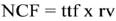
Firstly, a morphological inspection was performed with an inverted metallographic Nikon Eclipse MA 100 microscope under 3 magnifications: 50X, 100X, 200X (Figure 1).
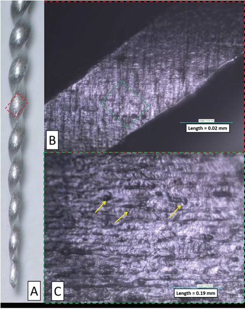
Figure 1 Morphological inspection of a TFA file. a) General view of TFA file (50 x). b) Cross-sectional area of a TFA file (100 x). c) More detailed amplification of a TFA file (200 x).
Figure 1a shows the general appearance of the longitudinal surface of a TFA-type rhyme. Figure 1b shows a close-up view of the cross-sectional area of the file, in which the marks of the manufacturing process of the file are appreciated. Figure 1c can be seen in more detail, the manufacturing lines described above, see yellow arrows.
All the instruments that presented defects or microcracks were excluded from the study.
Number of cycles to fracture
Number of cycles to fracture (NCF) of each instrument was determined using formula (1).
For the K3XF-C instruments, the speed indicated by the manufacturer is 350 rpm. For TFA-C instruments, the speed is 500 rpm. For the K3XF-A and TFA-A samples, the TF-Adaptive function was used, which has a speed of 500 rpm.
In the case of the K3XF-C group, the average number of cycles up to the fracture at 350 rpm was 45,675 cycles. For the TFA-C group this number was 36,667 cycles at 500 rpm.
On the other hand, 60,083 cycles were reported for the K3XF-A group at a speed of 500 rpm. Finally, it was found that for the TFA-A group 53,583 cycles were required to reach its fracture at 500 rpm. The K3XF-A group was the most resistant of the 4 groups evaluated (Figure 2).
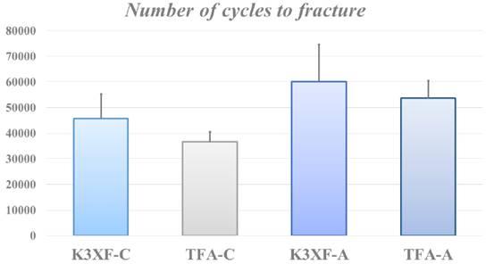
With respect to the time in seconds (s) required to reach the fracture. The K3XF-C group needed a time of 131 s, the TFA-C group was fractured in only 73 s, with respect to the K3XF-A group, a time of 120 s was reported and the TFA group -A took a time of 107 s to attain the fracture (Figure 3).
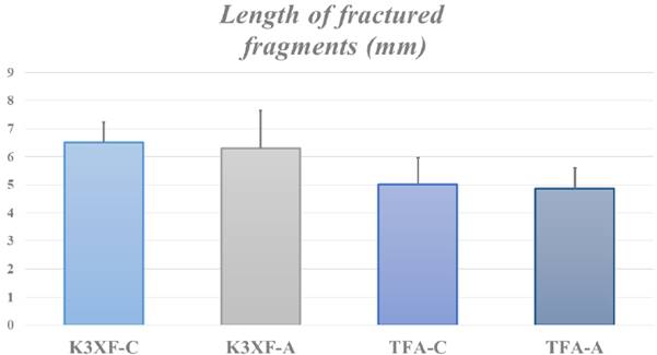
Length of fractured fragments
After the fracture of the rotating instruments, the length of the fractured fragments was measured to determine if mechanical damage occurred in the same area of the instrument. For the K3XF-C group, the measured fragments had a length of 6.51 mm, for the group K3XF-A a mean of 6.29 mm, in the case of the group TFA-C a length of 5.02 mm and finally, the group TFA-A obtained the smallest length of 4.86 mm (Figure 4).
Statistical analysis
Time to fracture (seconds)
Because the obtained results cannot be compared in a single test, an ANOVA was performed, the result of which shows that there is a statistical difference between some of the groups (p <0.05).
For the above, a pair of groups were compared at a time until the combinations were exhausted. A student t-test was used for two independent samples.
Regarding fracture time, the K3XF-C group had a mean of 130.5 ± 27.3 s and the TFA-C group averaged 73.3 ± 7.74 s, hence TFA-C group files break faster than the K3XF-C.
K3XF-A group has an average of 120.2 ± 29 s, compared to the K3XF-C group. There is not an important difference in time for fracture. Comparing the groups K3XF-C (130.5 ± 27.3 s) and the TFA-A group (107.2 ± 13.8 s). There is no statistically significant difference in time for fracture. On the other hand, TFA-C limes break faster than the K3XF-A. Statistically evaluating the groups TFA-A and TFA-C, it was found that TFA-C group files break faster than the TFA-A.
Number of cycles at fracture
When comparing the groups K3XF-C (45675 ± 9541 cycles) and the TFA-C (36667 ± 3869 cycles). The difference is statistically significant, since the files of the K3XF-C group require a greater number of cycles for the fracture than the files of the TFA-C group. About the comparison between the K3XF-C group with K3XF-A (60083 ± 14572 cycles). There is not an important difference in the number of cycles for the fracture.
Among the groups K3XF-C and TFA-A (53583 ± 6873 cycles), the number of cycles for the fracture are similar. On the other hand, the difference is wide between the TFA-C and K3XF-A groups, since the K3XF-A files require a greater number of cycles for the fracture than the TFA-C group.
Finally, the comparison between the TFA-C and TFA-A groups showed that the difference is evident, the TFA-A files require more cycles for the fracture than the TFA-C files.
Fracture pattern
Figure 5a shows the general appearance of the fracture of a K3XF-C file in which a flat surface and multiple fracture beginnings (green arrows) are observed, also the advancement of the fracture propagation lines by fatigue (yellow dotted lines). This image also highlights the rupture of one of the edges (yellow circle). Figure 5b shows a close view of the fragile fracture zone in which the grain fractures (green lines) can be seen. On the other hand, figure 5c shows grain breakage in which the flat fracture morphology (green dashed lines) is more obvious. It is important to note that these samples had an average rupture force of 6.84×10⁹ GPa, with a fracture diameter of 0.75 mm and a fracture length of 6.51 mm. Whose average area was 4.4×10⁻⁷ m2 .
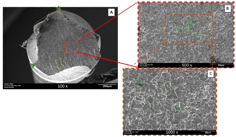
Figure 5 a) General appearance of the fracture surface of a K3XF-A file; this image also highlights the rupture of one of the edges. b) and c) Close views of the fracture surface in which the fracture after granularity is appreciated and many characteristic starts of fatigue fractures.
In the case of TFA-C files, Figure 6a shows the general appearance of the fracture of a TFA-C file in which a flat surface is well as the beginning of fracture (green arrows). It is important to note that the edges of the file are complete. Figure 6b shows a close view of the fragile fracture zone in which the fractures of the grains (green lines) can be seen.
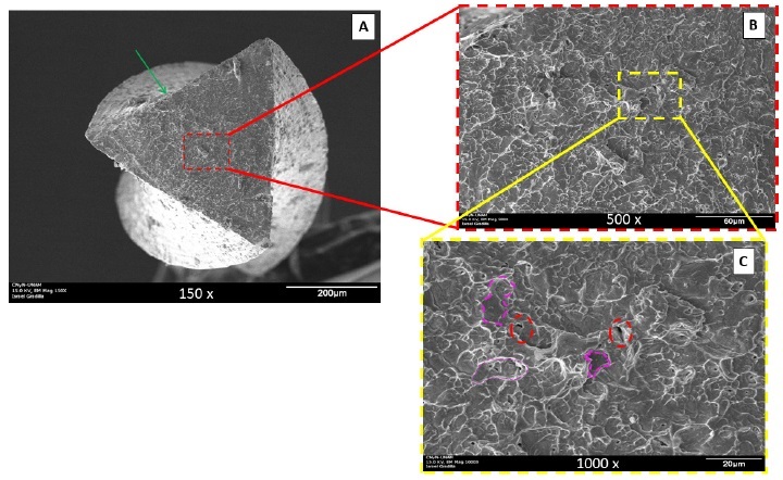
Figure 6 a) General appearance of the fracture surface of a TFA-C file. b) and c) close views of the fracture surface in which the fracture after granularity is appreciated and many characteristic starts of fatigue fractures. It is important to note that the edges of the file are complete (200X).
Figure 6c shows in greater detail the transgranular morphology rupture, typical of fatigue fractures (green dashed lines). In this image, we can see some cavities (black dotted lines) which could act as stress concentrators. It is important to note, that these samples had an average breaking stress of 1.18×10¹⁰ GPa, at a fracture diameter of 0.66 mm and a fracture length of 5.02 mm. Average area: 3.45×10⁻⁷ m2 (Figure 6).
Y. Shen, et al., compared the cyclic fatigue strength between K3 and K3XF in continuous rotation in wet and dry environments. They concluded that K3XF in wet environment was more resistant than the other groups (1146 ± 192 revolutions to the fracture) 4.
In our study, the instruments were not evaluated in a humid environment, however, we agree with the results of these researchers, where K3XF presents greater resistance to cyclic fatigue in continuous rotation than TFA in continuous rotation.
Another study, compared the resistance to cyclic fatigue of three Nickel-Titanium instruments (K3, K3XF and TF) under continuous and reciprocating motion (at 300 rpm both movements); used a total of 210 files (30/06), 60 K3, 60 K3XF, and 90 TF, divided into 7 groups (30 files in each group). The results obtained were better resistance to cyclic fatigue under reciprocating motion for the three rotary systems, standing out K3XF. Under continuous movement K3XF was more resistant than K3 and TF. There is no antecedent evaluation of continuous rotation and adaptive movement in two different rotary instruments 6. However, this study, showed similar results compared to our experiments, since K3XF in adaptive movement has greater resistance to cyclic fatigue than the other groups. Among the groups of continuous rotation, K3XF was the one that achieved better results.
Finally, it was evaluated the effect of autoclaving on the cyclic fatigue strength of four rotary systems: K3, Mtwo, Vortex, and K3XF. The K3XF instruments that were subjected to the sterilization cycles proved to be more resistant than those that were not sterilized, with a significant difference of 111 cycles.
The other rotating systems showed no significant difference among those who were sterilized and those who did not. Although the samples from our study were not subjected to sterilization cycles, we coincided with the results between the continuous rotation group, where K3XF presented greater resistance to cyclic fatigue than TFA 8,16.
Conclusions
In this study, we demonstrated that K3XF-C and K3XF-A instruments are more resistant to cyclic fatigue than TFA-C and TFA-A, with a statistically significant difference (p <0.05). Also, between the TFA-C and TFA-A groups, TFA-A showed greater resistance to cyclic fatigue with a statistically significant difference (p <0.05). Of all the groups, K3XF-A was the one that had the best resistance to cyclic fatigue.
Another conclusion is that the adaptive movement significantly improves the cyclic fatigue strength in either instruments, although the manufacturer recommends using only the TFA rotary system.
In future research, it will be performed an autoclaving and immersion cycles in sodium hypochlorite to be able to determine by a fault and fractography analysis the separation origin of rotary instruments. It is worth mentioning that the operator could significantly influence the decrease in resistance to cyclic fatigue due to the misuse of rotary instruments.

