


 text new page (beta)
 English (pdf)
 Article in xml format
 Article references
 Send this article by e-mail
 Cited by SciELO
  Similars in
SciELO
Similars in
SciELO 
 Permalink
INTRODUCTION
In traditional surgery, skin layers are literally cut to access the abdominal cavity of the patient, thus leading to postoperative discomfort, large scars and extended recovery times. In response to these disadvantages, minimally invasive surgery appeared [1], which is oriented to developing techniques allowing minimal intervention in the physiological structure of the subject [2]. This is achieved by accessing the interior of the human body by making small incisions between 5-15 mm in diameter through which laparoscopic instruments (i.e. forceps, graspers, cauterizers, extractors, cameras, etc.) are introduced. One of the problems in laparoscopic surgery occurs when surgeons mistakenly cut arteries [3, 4,5,6]. The National Practitioner Data Bank (NPDB) mentions that during the 1990-2004 period, there were 191,804 medical errors that took place just in the United States of America, of which 67% were attributed to qualified surgeons [7]. The deaths or consequences caused by these errors give as a result very high compensation fees [8]. In Mexico, traditional (i.e. non-laparoscopic) surgeons must observe the NOM-026-SSA3-2012 regulation [9], which stipulates all procedures for the practice of major outpatient surgery [10]. However, the real scenario is not very encouraging since overpopulation of pending surgeries, poor quality of equipment in the facilities, stress of the activity itself, and communication errors among the participants, involves developing alternative methods in the field to avoid accidentally cutting any artery. One of these processes is the thorough search of the physiological connection of the artery in question, which increases the time, costs and stress, and the challenge is even greater in a laparoscopic environment. Nevertheless, in the scientific literature, some proposals of devices designed to detect anatomical structures before performing some dissection in laparoscopic environments can be found. Most of these proposals usually implement somewhat complex devices and/or algorithms such as: standard and infrared cameras (i.e. infrared charge-coupled detectors), standard and infrared light sources, light filters, software and hardware for image processing, standard and infrared monitors etc., which could make these systems more expensive to bring to the market, not to mention that many do not have the capacity to differentiate between veins and arteries [11,12,13]. This article presents the innovation made to a conventional laparoscopic instrument (termed identifier), in which an automatic function of veins and arteries identification is adapted, using the light reflection technique [14, 15]. The identifier was tested in vitro with whole human blood samples and in vivo directly on canine model blood vessels.
METHODOLOGY
Hardware
As shown in Figure 1, a 5 mm WISAP laparoscopic forceps model MAI905330 was fitted with a reflective-optical sensor (ROS) composed of a LED and a light dependent resistor (LDR) VT43N2. On the upper part of the forceps, an electronic module composed of: an Arduino micro ATmega328 (μC) card, a radio frequency transceiver NRF24L01 (RFT), and a force sensitive resistor FSR-0.6 (FSR) were adapted to the manipulator.
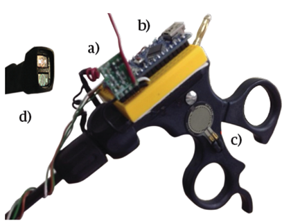
FIGURE 1 A laparoscopic forceps showing the adaptation of the electronic components. (A) RF Transceiver, (B) Microcontroller, (C) Force Sensor Resistor and (D) Reflective-Optical Sensor
When the surgeon presses the FSR with his thumb from the forceps manipulator, the LED of the ROS emits a light with a certain wavelength that impinges on the blood vessel to be identified either as an artery or as a vein. The LDR registers the light reflected from the blood vessel, converting it into voltage, which is collected by one of the analog inputs. The μC processes the data using a decision algorithm programmed in C++, which is explained in section “Automatic Detection”. The decision made, whether it is a vein or an artery, is transmitted wirelessly to a receiver module via the RFT using a carrier frequency of 2.4 GHz with the intention that all the team involved in the surgery to be aware of the identification of the blood vessel. The receiver module also contains an RFT connected to a μC, which receives the decision and communicates it to the surgical team in an audible and visual manner. The receiver module activates a buzzer with an audible frequency of 250 Hz for veins and 1600 Hz for arteries, both with a duration of 250 ms. In addition to this, an RGB LED is issued by emitting a red or blue color if the blood vessel is identified as a vein or an artery, respectively. If the identifier is inactive or is in an indeterminate situation, the RGB LED emits a green light. Figure 2 schematically shows the transmitter and receiver modules.

RESULTS AND DISCUSSION
In Vitro Tests
The identifier was tested with 5 venous blood samples and 5 arterial blood samples, which were taken from 10 different adults who went to a general hospital in northwest Mexico for different clinical reasons. Blood samples were placed in 3 ml vials and placed inside a dark chamber to test the identifier, and to avoid that the light emitted or read by the ROS was contaminated by other surrounding light sources (i.e. noise). The time, from the taking of the blood sample, its placement in the dark chamber, and the test with the optical-reflective device, was not more than 20 minutes to avoid the degradation of the sample.
Previous studies have shown that hemoglobin (Hb) and oxyhemoglobin (HbO2) exhibit different levels of radiation absorption at different wavelengths of light. It has been observed in vitro experiments that up to about 600 nm the absorptions between Hb and HbO2 are very similar, making it difficult to differentiate them. However, the absorption becomes much more differentiated from the wavelength of red light (about 650 nm) to the wavelength of infrared light (about 950 nm) [14, 16, 17]. Based on these fundamentals, the identifier was tested with each of the blood samples using yellow light (λ = 620 nm), orange (λ = 670 nm), red (λ = 750 nm) and infrared (λ = 850 nm). Figure 3 shows the results of these tests.
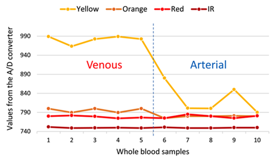
FIGURE 3 Digital values obtained by the A/D converter of the reflected light captured by the ROS of each wavelength incident on each blood sample. Left of the vertical dashed line is venous blood and the right of the line corresponds to arterial blood.
The first 5 samples correspond to venous blood and the remaining 5 to arterial blood. It can be observed that as the wavelength increases, the separation (in magnitude order) of the reflected light readings between the veins and arteries decreases. It can also be observed, for example, that the reflected yellow light is the one that could best discriminate between veins and arteries. This can also be seen in the statistics presented in Table 1.
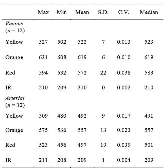
TABLE 1 Central-tendency statistics of the results (i.e. deci mal representation of the output binary values of the A/D converter) obtained from the ROS tests with 4 different wavelengths, applied to the 'in vitro' venous and arterial blood samples.
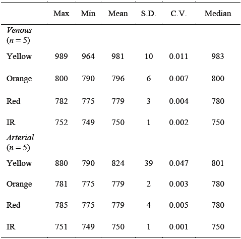
Max = maximum value; Min = minimum value; S.D. = standard deviation; C.V. = coefficient of variation; IR = infrared.
If we compare, for example, the means or medians of each reflected light, it is seen that there is sufficient separation, in orders of magnitude, between veins and arteries corresponding to the yellow light and that as the wavelength increases, the separation, in orders of magnitude, of statistics between veins and arteries drastically decreases, making it difficult to discriminate. It is also noted that data dispersion, such as standard deviation and coefficient of variation, are higher in arterial blood than in venous blood for reflected yellow light.
In Vivo Test
Following the NOM-062-ZOO-1999 [18, 19], veterinarian surgeons performed an open surgery in vivo of pelvic abdominal type on a 5 years old male canine model. The identifier was tested using yellow (λ = 620 nm), orange (λ = 670 nm), red (λ = 750 nm) and infrared lights (λ = 850 nm) over 4 different blood vessels on the abdominal cavity of the canine model, previously identified by a veterinarian physician as veins (n = 2) and as arteries (n = 2). The surgeon placed the ROS of the identifier perpendicularly on the surface of each blood vessel (i.e. 2 veins and 2 arteries) and took readings for each reflected light color on 12 different points of the vessels. Therefore 2 vectors of 12 readings for veins and 2 vectors of 12 readings for arteries were obtained. Then, the 2 vein readout vectors and the 2 artery readout vectors were averaged separately to obtain a single data vector (n = 12) for vein and a single data vector (n = 12) for artery. It can be seen on the graphs in Figure 4 that the yellow and orange reflected lights follow a similar pattern, although it can be noticed that the orange light is the best to make the differentiation between veins and arteries.
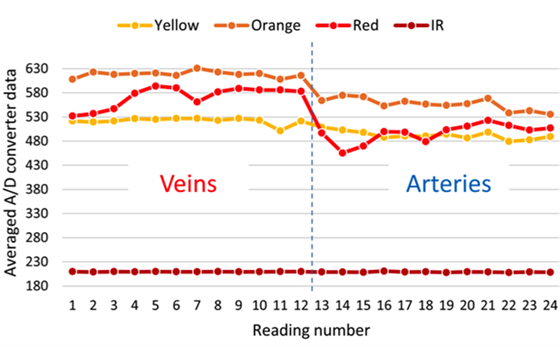
FIGURE 4. Averaged digital values obtained with the A/D converter of each reflected light from the blood vessels in the canine model, captured by the ROS. The left side of the vertical dashed line corresponds to venous blood and the right side to the arterial blood.
The statistics of these results, shown on Table 2, also show important differences that could be used to automatically differentiate a vein from an artery. For example, by establishing cutting points, thresholds or ranges between the minimum values of light reflected from the veins and the maximum values of light reflected from the arteries. This idea is explained in more detail in next section.
TABLE 2 Central-tendency statistics of the results (i.e. decimal representation of the output binary values of the A/D converter) obtained from the ROS tests with 4 different wavelengths, applied to the 'in vivo' canine model.
Max = maximum value; Min = minimum value; S.D. = standard deviation; C.V. = coefficient of variation; IR = infrared.
Automatic Detection
To differentiate between veins and arteries, it was decided to work with the orange light (λ = 670 nm), since this was the light that showed a wider range of values between the minimum value of the light reflected from the veins and the maximum value of the light reflected from the arteries without overlaps. In other words, in all cases of wavelengths tested, with exception of the orange light, local minimum values (Figure 4) or minimum mean values (Table 2) of light reflected from veins were sometimes observed as being below local maximum values or maximum mean values of light reflected from arteries (i.e. overlapping values), respectively. Conversely, local maximum values or maximum mean values of reflected light from arteries sometimes were above local minimum values or minimum mean values of light reflected from veins, respectively. These characteristics of the orange light allowed establishing a better margin to perform the automatic separation between veins and arteries. Figure 5 shows the thresholds (i.e. cutting points) established between the values zone corresponding to the veins and the ones that correspond to the arteries, estimated by using the following Equations:
Where:
CPV = Cutoff point or threshold that defines the zone to classify a blood vessel as a vein.
CPA = Cutoff point or threshold that defines the zone to classify the blood vessel as an artery.
x̄V = Mean of the data vector of the reflected light by the veins, digitalized with the A/D converter.
x̄A = Mean of the data vector of the reflected light by the arteries, digitalized with the A/D converter.
σV = The standard deviation of the data vector of the reflected light by the veins, digitalized with the A/D converter.
σA = The standard deviation of the data vector of the reflected light by the arteries, digitalized with the A/D converter.
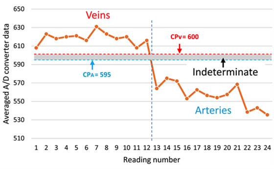
FIGURE 5 Cutting points (horizontal dashed lines) marking the regions for the classification of the veins and arteries, CPV and CPA, respectively. The shaded region between both CP is defined as indeterminate zone.
The means and medians of most of the values measured by the identifier from the different reflected wavelengths in the tests performed both in vitro (Table 1) and in vivo (Table 2) showed very similar values, therefore a good degree of symmetry can be assumed in the data distribution functions. Thus, the standard deviation in equation (1) and (2) is multiplied by a factor of 3 to prevent the probability that any future measurements performed by the identifier tend to deviate too far from the means.
This way, once the ROS picks up the reflected light from a blood vessel and inputs it to the μC, this processes the digitalized data by the A/D converter through an algorithm programmed in C++ and decides if the reflected light comes from a vein or from an artery, following the flowchart and conditions shown on Figure 6 and Table 3, respectively.
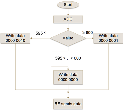
FIGURE 6. Flowchart describing the logic executed by the μC in the transmitter module. The photo-resistor voltage of the ROS is read by the ADC and assigned to an integer variable called "Value", which is compared with CPV (i.e. 600) and CPA (i.e. 595) thresholds. The result is written in an 8 bits register called "data" and sent to the receiver module via the radio frequency module.

In other words, if the A/D value delivered to the μC is equal or greater than the CPV threshold (i.e. 600) then the binary number 1 is sent through the RFT transmitter to the receiver module. The μC of the receiver module, also programmed in C++, once received the binary number, executes the algorithm following the flowchart and response decision shown on Figure 7 and Table 4, respectively, activating the buzzer with an audible frequency of 280 Hz and turning on the red color of the RGB LED to alert the surgeon and medical staff that a vein has been detected. If the A/D value is equal or lower than the CPA threshold (i.e. 595) then the binary number 2 is sent to the receiver module. Then, the μC of the receiver after receiving the binary number 2 executes the response conditions by activating the buzzer with an audible frequency of 1600 Hz and turning on the blue of the RGB LED, to alert the surgeon and medical staff that an artery has been detected. If the A/D value reaching the receiver module is higher than 595 or lower than 600, then there is no sound and only the RGB LED green is on, informing the surgeon and medical staff that it was unable to identify the blood vessel as either a vein or an artery. Sound or visual warning to the surgeon and his assistants, on the identification of the blood vessel, is with the intention that the most experienced of the medical team can help in the confirmation of the identification of the blood vessel; the less experienced can be trained and the students learn. The full identifier device is shown in Figure 8.
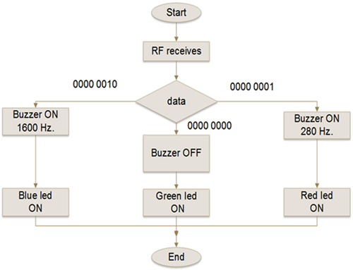
FIGURE 7. Flowchart describing the logic that executes the μC of the receiver module. When the RF module receives the discrimination value from the RF transmitter, it passes it to the microcontroller which writes it to a variable called "data". Then it compares it with three different values stored in registers of 8 bits and depending on it activates the PWM outputs to turn on the buzzer or the digital outputs to turn on the LED, as the case may be.


In this research work, 4 light wavelengths emitted by the identifier’s ROS were tested, aiming them to hit over different in vitro and in vivo blood samples, with the purpose of observing the reflective responses and assess the feasibility for them of being used to discriminate between venous and arterial blood. The in vitro tests showed that both yellow and orange lights (i.e. λ = 620 nm and λ = 670 nm, respectively) deliver a good discriminatory response, although the tests were performed using non-pulsatile arterial blood and by controlling the interference of the surrounding light (i.e. noise).
On the other hand, the in vivo tests showed that the best wavelength to differentiate veins from arteries was the orange light (i.e. λ = 670 nm), even without controlling other surrounding light sources (i.e. noise) in the surgical room. Once the reading and response conditions were programmed into the identifier, this was blindly tested on different arteries in the canine model, without generating any erroneous identification of veins or arteries. The proposed identifier should be tested in other specimens in vivo in laparoscopic surgeries for better validation. The behavior of different identifier’s ROSs (i.e. different wavelengths of light) should also be studied when exposed to the light sources during laparoscopic surgeries in vivo. These experiments are contemplated to be carried out in future works.
The veins and arteries identifier prototype is under experimentation and still has several practical limitations. Normally, 3 or 4 incisions are performed in laparoscopic surgery where the ports are inserted, which are used to channel the different surgical instruments. Sometimes it is necessary to exchange instruments through the ports, so up to now the prototype is intended for the surgeon to use it every time he hesitates if what he tries to cut is a vein or an artery. For now, the surgeon would have to decide whether to give a higher priority of use to the identifier, and dedicate one of the ports only for the manipulation of the identifier. Otherwise, the surgeon would have to be alternating between the use of the identifier and other laparoscopic instruments whenever he deemed it necessary. Other important aspects are the protection and sterilization of the identifier. All electronic circuitry must be encapsulated in such a way that they must be immune to possible spills of liquids, gases or bodily fluids; but should also allow sterilization using conventional methods such as ethylene oxide, hydrogen peroxide, or glutaraldehyde.

