


 text new page (beta)
 English (pdf)
 Article in xml format
 Article references
 Send this article by e-mail
 Cited by SciELO
  Similars in
SciELO
Similars in
SciELO 
 Permalink
Introducción
Tube hydroforming (THF) offers advantages over the traditional forming process, in recent years, the THF has become an alternative manufacturing process for medium range quantity production. Some of the advantages over the traditional forming process are: a) dimensional accuracy, b) reduced springback, c) weight reduction, d) uniform wall thickness, and e) reduced scrap (Singh, 2003).
At the beginning of the century, out keeping began the use of numerical simulation of hydroforming of sheet and few studies that have been made on tubes. Most authors use Finite Element Analysis (FEA) for numerical simulations, and, in this work, the FEA method was also used based on ANSYS software (Shinde, Patil, & Joshi, 2016).
Due to the recent development in the hydroforming process and the complex mechanism of plastic deformation, some drawbacks can be found, where the most common are the slow cycle time, limited experience in the design of tools and equipment, and lack of specialized literature (especially in Spanish).
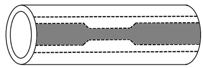
A brief description of the tube hydroforming process is shown in Figure 1. The tube is held between two die halves with the desired form. The first step is to fill the tube with a low-pressure fluid and, once removed the air trapped inside, a combination of axial force and internal high pressure is applied. Consequently, the tube expands and is forced to attain the shape of the die. However, axial feeding and internal pressure should be applied simultaneously to improve material formability (Langerak, Rout, Verma, Manikadan & Haldarl, 2004).

Three key parameters are involved in THF modeling. The first parameter is the friction between the die and the tube to be formed, and a lubricant is used to reduce the buckling, bursting, surface wrinkling, and tool wearing. When internal pressure is applied to the tube, the tube wall will be pressed against the die; this initial contact zone is called the guided zone. Once the tube material slides in axial direction into the cavity, this process is called the expansion zone. (Jun-Jang, Wen-Da, Gang, Shi-Qiang & Shi-Jian, 2011). The second parameter to be investigated in THF is the applied pressure in the internal wall of the tube and the axial feeding, and the following pressures were applied: low pressure, high pressure, multi-pressure, and hydro-bulge.
Low-pressure hydroforming is limited to 83 MPa (12 000 psi); this value was determined by the Tube and Pipe Fabricators Association. Under this low pressure, the total expansion on the tube is up to 3%, minimal change in thickness is present, and cycle time and investment in equipment are lower than other hydroforming processes.
For high pressure hydroforming of up to 414 MPa (60 000 psi), higher plastic deformations due to the high stresses generated during the process were observed. For welded tubes, quality and bursting can be a decisive factor; where thickness variation can be present, especially in corner regions. Applying an internal pressure in the tube results in a uniform distribution of forces in the internal surface of the tube, reducing abrupt changes in stresses in the process, allowing a maximum degree of plastic deformation, improving dimensional accuracy, and uniforming thickness in the tube wall and low springback.
Finally, the third parameter investigated is the correct determination of material characteristics that can improve accuracy in the prediction of process parameters for THF applications (Yeong-Maw & Yi-Kai, 2006). Deformation mechanism in tube hydroforming is under biaxial strain deformation and biaxial stress state; however, applying plasticity, membrane and thin-walled theories are rather limited, but parameters for hydroforming can be achieved. In the investigation presented by Koc & Taylan (2002), several analytical equations were developed, with relevance in the prediction of the yielding pressure and bursting pressure, helpful in early stages of the design and development of the desired part.
Material and method
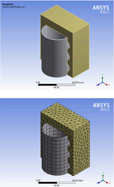
A geometrical 3D CAD model of the dice and the tube to be hydroformed was developed in SolidWorks® 2014 software, as shown in Figure 2. The model was exported in IGS format to be utilized in the structural module of ANSYS® workbench 16.2 for the meshing and the application of boundary conditions. The model is an assemble, consisting of two dice and one tube as shown in Figure 2.
The physical properties of the material are usually the result of standardized tests, previously to a manufacturing process such as cold forming for sheets and cold rolling for tubes. However, grain orientation and homogeneity are affected, and different values in different directions of the structure are present, making new mechanical tests necessary to obtain those modified values.
The initial material is an aluminum 6061-T5 tube with a diameter of 31.75 mm (1 1/4”) and 1.4 mm thick. In section 6.9 of the ASTM-E8/E8M-09 “Standard test methods for metallic materials”, the dimension of the specimen and the manufacturing way are specified, as shown in Figure 3 (ASTM E8/E8M-09 Standard, 2016).
Source: Authors’ own elaboration.
Figure 3 Location from which longitudinal tension test specimens are to be cut.
The tensile tests were done at room temperature using a Shimadzu Universal Testing Machine, model AG - X Plus, with a velocity test of 3 mm/min. The values of force and displacement were obtained with the Trapezium Materials Testing Operation software in the materials characterization laboratory at the Universidad Politecnica del Valle de Mexico (UPVM) at room temperature. The data obtained are shown in Table 1. Thirty-two specimens were tested; an average of the stress-strain deformation obtained is shown in Figure 4. Hollomon’s equation was utilized to obtain the strength index (K) and the plastic strain the strain hardening exponent (N), data necessary for the numerical simulation boundary conditions:
Tabla 1 Comparison of experimental vs literature mechanical properties.
| Property | Experimental | Literature |
|---|---|---|
| y | 95 MPa | 110 MPa |
| u | 218 MPa | 210 MPa |
| Elongation | 13% | 16% |
| N | 0.365 | 0.20 |
| E | 92.8 GPa | 69.8 GPa |
Source: ASM Aerospace Specification Metals, Inc.

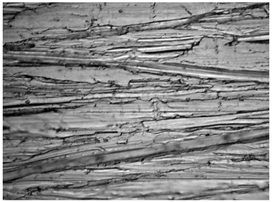
Optic images of macrostructures were obtained by using a Carl Seizz microscope model Axio Vert AX10 in the materials characterization laboratory at UPVM (Figure 5).
Source: Authors’ own elaboration.
Figure 5 100x magnification photography of the internal face of the specimen test before the tension test.
The geometric model was imported in ANSYS® 16.2; the purpose of creating a solid model is to mesh that model with nodes and elements. Once this is performed, a time-dependent bilinear isotropic hardening (BISO) model was selected in the Workbench software. The BISO model uses the von Misses Criteria coupled with isotropic hardening in the material. In isotropic hardening, the yield surface expands uniformly in all directions with plastic flow. The material properties of the tube obtained experimentally (Table 1) should be captured in the material settings module as new material.
The BISO model is time-dependent; three steps of loads were applied. In the first step a 3MPa pressure was applied, in the second step 7MPa was applied, and in the last step the pressure was withdrawn. A minimum of ten sub-steps and a maximum of 25 sub-steps were selected to ensure the path dependent response.
The analysis in the contact zone between the tube surface and the dice surface is performed with contact elements. Several methods are available; The Pure Lagrange Method and the Augmented Lagrange Method were evaluated. The Pure Lagrange Method guarantees no penetration between the contact faces, but convergence problems happened. The Augmented Lagrange Method was selected, even if it minimizes penetration and is less sensitive to contact stiffness, no convergence problems happened (ANSYS, 2012)
Results
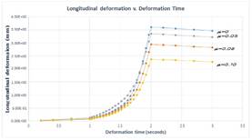
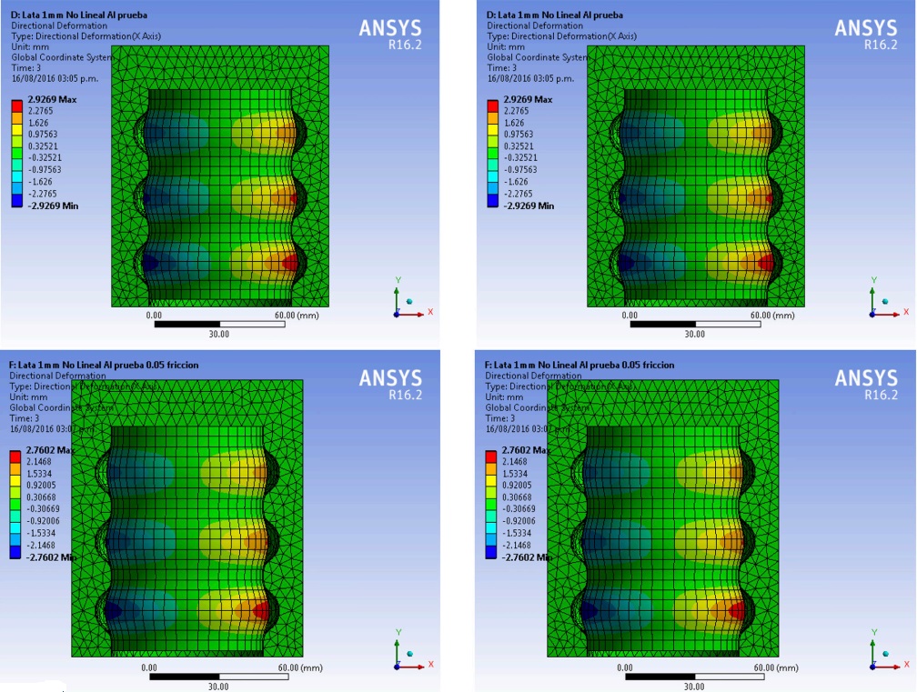
Four simulations were performed, friction between the tube and the dice were µ = 0, µ = 0.05, µ = 0.08, and µ = 0.10. A pressure of 7 MPa was applied in the internal face of the tube in three steps; on the first and third steps no pressure was applied (Ceretti, Attanasio, Fiorentino, Giorleo & Giardini, 2013). We quantified the differences between each simulation and observed that the frictionless model suffered greatest plastic deformation in radial and longitudinal direction, where springback was with an average of 4% in both directions (Figure 6).
Source: Authors’ own elaboration.
Figure 6 Longitudinal and radial deformation of the tube with µ = 0, µ = 0.05, µ = 0.08, and µ = 0.1.
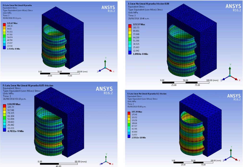
Permanent radial and longitudinal plastic deformation in the tube was achieved, maximum stresses were present on step two of the simulation, and final Von Misses equivalent stresses are in average 58% of their maximum present as shown in Figure 7. In all the cases, not a fracture on the tube was obtained.
Source: Authors’ own elaboration.
Figure 7 Radial deformation of the tube with µ = 0, µ = 0.05, µ = 0.08, and µ = 0.1.
Discussion
Studies on tube hydroforming simulation started since the beginning of the century (Abrantes, Szabo-Ponce, & Batalha, 2005), but almost no investigations of commercial aluminum tubes have been carried out. A strong relationship exists between friction in the surfaces and formability. The utilized yielding pressure was calculated with the equations developed by Koc & Taylan (2002), a higher pressure of 7 MPa should result in superficial stress above the breaking point. Numerical simulations with more than three steps were made, applying pressure for longer periods in the inner walls of the tube, but no significant changes were observed. For optimization in computing time, three steps were utilized in the numerical simulations presented in this study.
An experimental design is proposed to obtain the correlation between pressure, application time, friction, and deformation. A hierarchical linear regression is proposed; this type of analysis is most commonly used when the cases in the data have a nested structure.
Plastic deformation is a time-dependent process; in this study, on the ANSYS program for a simulation THF process three steps were utilized for the loading path. In the initial time, a pressure of 3 MPa was applied; in the second step, a 7 MPa was applied; and, finally, the pressure was withdrawn. The obtained results agreed with the analysis of the literature, presenting low significant errors. Future work could extend not only to numerical simulation, but design of experiments can also be utilized to show correlation factors and relations between the boundary conditions for the design and manufacture of THF components.
Conclusions
Due to the lack of complete and accurate data of the mechanical properties of the aluminum tube (ultimate stress, yield stress, strain hardening index, and strength coefficient), experimental data was obtained. Thirty-two specimens were tested; the data utilized in the numerical simulation was an average of the data obtained according to the ASTM standards.
Substantial differences between experimental data and the one consulted in the literature were observed; the average applied load for yielding in the material was 15 MPa, 14% less than the one reported by ASM Aerospace Specification Metals, Inc.
In all performed numerical simulations the applied pressure was kept the same, and the longitudinal and radial deformation, springback, and Von Misses stress in the tube were modified by the friction. In order to obtain the desired forming profiles with a higher friction coefficient, higher pressures should be necessary.
This study shows that numerical simulation represents a helpful tool for initial prediction in the design and development of specific problems in THF in initial stages, shortening the lead times in manufacturing and reducing costs at this stage. The design of the experiments and the experimental test can be developed for future works.

