


 text new page (beta)
 English (pdf)
 Article in xml format
 Article references
 Send this article by e-mail
 Cited by SciELO
  Similars in
SciELO
Similars in
SciELO 
 Permalink
1 Introduction
The spontaneous capillary rise of a viscous liquid within a vertical wedge-shaped cell, made out of two flat plates touching at an edge and having a very short angle between them, was experimentally studied for the first time by Brook Taylor [1] and Francis Hauksbee [2] in 1712, showing the existence of the capillary action; as well as the formation of equilibrium profiles, shaped as rectangular hyperbolas. We will refer to this configuration as the Taylor-Hauksbee (T-H) cell.
Surprisingly, such configuration has been very helpful to understand the capillary rise in a myriad of natural and manufactured functional surfaces having open, nano or micro V-grooves. For instance, a study of the peristome surface of Nepenthes alata (a carnivorous pitcher plant) showed that the plant has taken full advantage of the corner geometry to apply the straightforwardional control of the liquid flow [3,4,5]. Natural functional surfaces like peristome surface give inspiration for designing and fabricating functional surfaces and materials with wide applications including water transport for agricultural drip irrigation over long distances, controllable self-lubrication and smart and controllable microfluidic devices [5], to name a few. Implementations of V-grooves in devices at a larger scale has been done to improve the heat transfer capacity of heat pipes [6] as well as open capillary siphons [7]. Coincidently, it has recently been proposed that capillary corner flow is also an important transport mechanism during the spreading of viruses and bacteria [8,9].
From a theoretical point of view, Tang et al. [10] studied the capillary rise along the angular corner formed by the contact of a thin rod inside a larger vertical tube (whose diameter is smaller than the capillary length
In a theoretical treatment of tilted T-H cells, carried out by Tian et al. [17], the capillary rise and the time evolution of the free surface, far from the horizontal surface of the liquid, were studied. Such study was motivated since the microstructures on the peristome surface resembles the geometry of intersecting plates but with the arista being curved and tilted. Based on the Onsager principle, i.e., a method to find the minimum of the Rayleighian, which is the summation of the change rate of the free energy of the liquid and the dissipation function, Tian et al obtained that the rise of the meniscus front also obeys, at large times, the
Motivated by the new applications, in the present work we will analyze the issue of the dynamic evolution of the free surface within a tilted Taylor-Hauksbee cell by using the lubrication theory approximation, which was previously used to model the capillary rise in vertical T-H cells [11]. Now, following this approach we formulate the Reynolds lubrication equations, in the tilted system, which allows us to obtain the simplest form the problem for the dynamic evolution of the free surface in the tilted system.
Our treatment, as backed by experiments, will provide evidence that the capillary rise of the meniscus, close to the sharp edge, is faster for larger inclinations and that it also follows the power law
To reach our goal, in the next Section we describe the problem and we obtain analytically the equilibrium surfaces in terms of the rotated and un rotated coordinate systems. Later on, in Sec. 3, we use said coordinate system in the lubrication theory to obtain the simplest set of equations possible. In Sec. 4, we performed a series of experiments, using glass-made tilted T-H cells and silicone oil, to obtain the dynamic evolution of the free surfaces before attaining the equilibrium surfaces. The physical parameters governing the experiments will be introduced in the numerical treatment to do a straightforward comparison between the theoretical and experimental profiles and to show that our theoretical approach is suitable. Finally, in Sec. 5, we present the main conclusions for this work.
2 Equilibrium profiles
2.1 The physical problem
The tilted T-H cell is formed when two plates touch at the edge and make a very short aperture angle
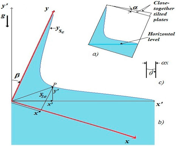
Figure 1 a) Depiction of a Taylor-Hauksbee cell, tilted at a clockwise angle β with respect to the vertical, and with a small aperture angle α. In this case the horizontal level of the liquid meets the lower corner on the left had side of the cell. b) Schematic indicating the two-dimensional Cartesian coordinate systems (x’, y’) and (x, y), with a common origin. The equilibrium free surface is
If liquid wets the plates, the contact angle θ obeys that θ < π/2, see Fig. 1c). As depicted in Fig. 1b), the profile of the free surface of the liquid in the tilted cell could also be described with the rotated Cartesian coordinate system (x, y), whose y-axis is attached to the arista of the cell. Notice that the rotated and the unrotated coordinate systems have the same origin. Our aim here is to analytically describe the free surface profiles in both coordinate system, which will also be useful in the formulation of the capillary rise equations, derived from the lubrication theory.
2.2 Cartesian coordinate systems
The actual equilibrium profiles evolve within the tilted T-H cells driven by the capillary action and limited by gravity. Therefore, the natural description of these profiles must carried out at the tilted (rotated) coordinate system (x, y). However, mathematically, it is possible to describe such profiles at the un tilted system (x’, y’), but in this latest coordinate system the profiles may not be one-to-one (injective) functions.
If we locate the point P in the unrotated coordinate system, said point has the coordinates (x’, y’), as seen in Fig. 1b), but the same point P in the system (x, y), rotated an angle β, is given by the transformation
and the location of the point P at the unrotated system, in terms of the coordinates (x, y), is given by
These transformations will become useful in the description of the equilibrium profiles, and in the capillary rise theory formulation.
2.3 The equilibrium profiles in the tilted system
Given the coordinate systems, it is straightforward to obtain the equilibrium free surface in the coordinate system (x, y), given that in said system, the curvature radius at the point P takes the value
notice that if β = 0 in Eq. (5), the classical equilibrium surface is obtained [11]
formally, from Eq. (5) it is clear that the equilibrium height of the liquid at the edge (when
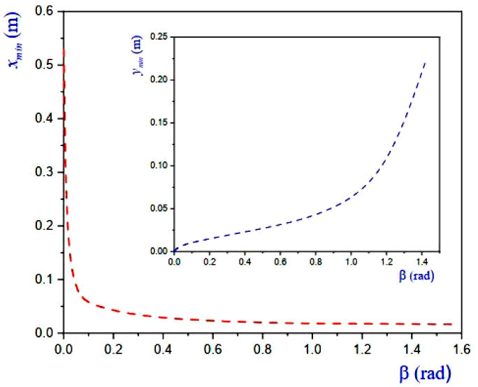
On the other hand, the equilibrium surfaces in the tilted system have their minima (when
it is clear that the position of xmin will be located at infinity if
it is clear that the position of ymin goes to infinity if
In experiments discussed later on the work fluid was silicone oil, a nonvolatile liquid at room temperature; which has the following nominal values: dynamic viscosity μ = 0.1 Pa s, surface tension σ = 0.0215 N/m and density ρ = 971 Kg/m3. The average contact angle, measured using the static sessile drop method, for silicone oil over flat glass was found to be θ = 0.122 ± 0.006 rad (7o) at room temperature Troom = 296.15 K. The plots in Fig. 2 were computed using previously available data and the aperture angle was taken to be α = 0.016 rad (0.95o). We show several plots of the equilibrium profiles (Eq. (5)), in which the positions of their minima in the rotated coordinate system (x, y) can be appreciated for several tilt angles β.
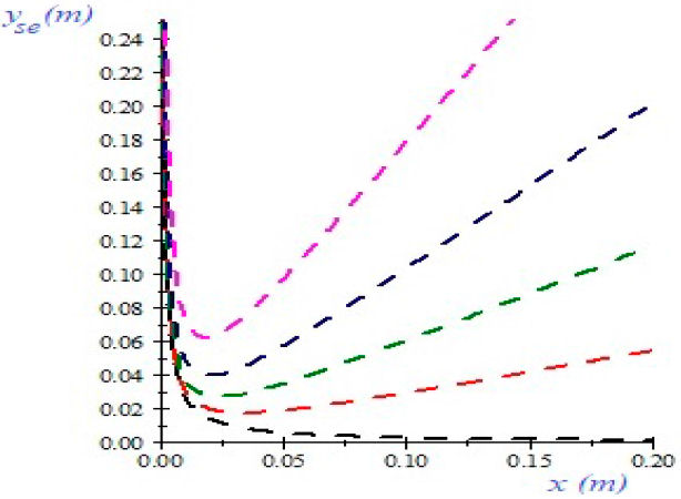
Figure 2 Plot of the equilibrium profiles (Eq. (5)), from the perspective of the rotated coordinate system (x, y), the aperture angle being α = 0.0166 rad (0.95o). The dashed curves belong to the tilt angles: black β = 0, red β = 0.2618 (15o), green β = 0.5236 (30o), blue β = 0.7854 (45o) and magenta β = 1.0472 (60o).
Employing the same data as in Fig. 2, the graphical behavior of the positions of xmin and ymin, for a continuum of values of β are given in Fig. 3, where the aforementioned observations of the locations of the minima, are confirmed.
2.4 Profiles from an unrotated coordinate system
It has been mentioned that it is also possible to plot the equilibrium profiles formed in the tilted cell, for the unrotated system (x’, y’). The equilibrium profiles in the unrotated coordinate system are obtained by introducing Eq. (5) into Eqs. (3)-(4), yielding
If we choose the plus sign in Eq. (9), we find for large values of x’ that
meanwhile, if the sign minus it is chosen, we find that
In Fig. 4 we plot the equilibrium profiles in the unrotated coordinates
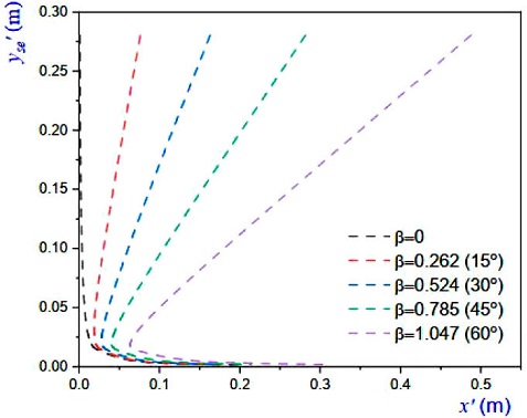
Figure 4 Plots of the equilibrium profiles (Eq.(9)) in the (x’, y’) coordinate system. The tilt and aperture angles are the same as those in Fig. 2.
In plots of Fig. 4 the upper part of each profile is given by Eq. (10) and the respective lower part of each profile is given by Eq. (11). Some experimental profiles will be shown later on.
3 Capillary rise: use of the lubrication theory
The film flow due to capillary rise in T-H cells occurs at small Reynolds numbers [11]. Therefore, we can use the Reynolds’ lubrication theory to compute the distribution of the modified pressure P and the rise of the meniscus. In the unrotated system said a pressure is P = p + ρgy’, where p is the pressure of the liquid referred to the pressure of the surrounding gas (pa) and y’ is the vertical distance from the the horizontal level of the outer liquid. By using Eq. (4) in the aforementioned modified pressure, it is straightforward to find that the form of this pressure in the tilted system is P = p + ρg(y cos β - x sin β).
The lubrication theory [11,19], uses the width-averaged flux per unit length given by q = (qx, qy) where
here, ys is the free surface in the tilted system. The modified pressure obeys the equation
at
which expresses that said pressure at the free surface is the sum of the capillary depression
At the evolving free surface ys, the kinematic condition (which states that the fluid does not cross the free surface) is given by
at
Equations (12), (13) and (14) will be solved under the following boundary conditions
The condition (15) imposes that the flux through the edge of the wedge (x = 0) is zero, Eq. (16) expresses that the modified pressure at the lower edge of the plates (y = 0 if the lower corner x = y = 0 is at the level of the outer liquid, as in Fig. 1) is also zero and finally, Eq. (17) states that far from the arista the free surface is very close to the horizontal level of the liquid. The problem described by Eqs. (12)-(14) will be solved numerically for a given initial condition
The system of partial differential equations subject to the boundary conditions was solved using an implicit finite differences discretization. A careful analysis of the solutions as functions of the spatial and temporal in-homogeneous meshes allowed us to find out that a 50 × 50 mesh is adequate to achieve an accurate solution. The numerical time step was variable; in the first stages of the phenomenon the time step was about 10-9 and it was exponentially increased as the phenomenon evolved. Typical calculations were made for a total of 20 000 time steps.
Incidentally, following the same approach as used in [11], but now for the tilted system, we find that the asymptotic self-similar solution for the meniscus of the thin layer close to the edge
4 Experiments
To compare the numerical dynamic profiles with those obtained experimentally, we performed a series of experiments with silicone oil. Ad hoc T-H cells having different inclinations of the arista were made with flat glass plates (3 mm thick) of different sizes. Wedges with different short angles were made by keeping the plates in contact along the arista and by fitting, between the glass plates, a thin metallic sheet, parallel to the arista, at a certain distance from it. Special care was taken to avoid any contact of the metallic sheet with the silicone oil during the profile formation. Each angle α, of a given cell, was computed through the measurement of the narrow space between the plates, at the rim opposite to the edge. On the other hand, the tilt angle β was measured using a digital clinometer (accuracy ± 0.1o).
In Fig. 5 we present pictures of the equilibrium profiles for three representative cases with inclination angles: 5a) β = 0 ± 0.002 rad, 5b) β = 0.524 ± 0.002 rad (30o) and 5c) β = 1.047 ± 0.002 rad (60o). In these experiments the mean aperture was α = 0.012 rad and the equilibrium profiles were photographed in all cases, one day after the T-H cells were brought into contact with the silicone oil.
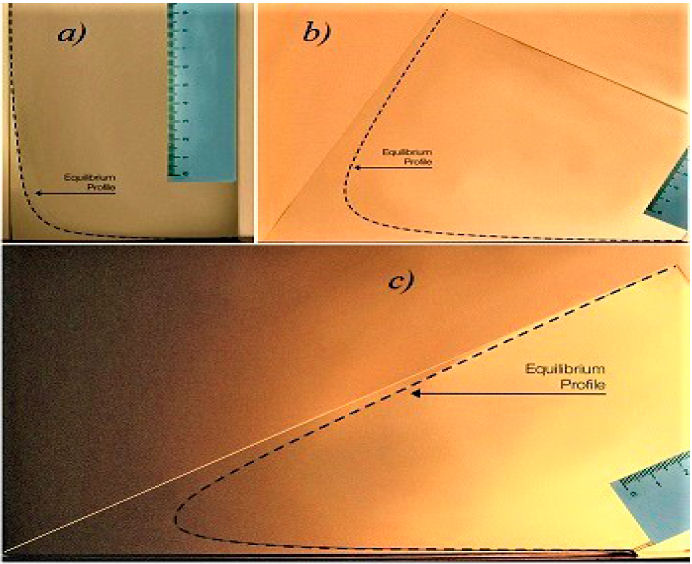
Figure 5 Pictures of the equilibrium profiles, indicated by dashed curves, at tilt angles: a) β = 0 rad, b) β = 0.524 ± 0.002 rad (30o) and c) β = 1.047 ± 0.002 rad (60o); where the mean aperture angle was α = 0.011 rad. Photographs were taken approximately one day after the start up of the capillary rise. The scale on the ruler is in cm.
Due to our assembly procedure of the T-H cells, the aperture angles α were different for every experiment. In Fig. 6 we show the plot of several instantaneous profiles in a cell having the same tilt angles as in Fig. 5, but the aperture angles were: 6a) α = 0.019 ± 0.0001 rad (1.0o), Fig. 6b)α = 0.008 ± 0.0004 rad (45o) and Fig. 6c)α = 0.010 ± 0.0005 rad (0.63o). It is evident that the scales in the plots were located on the unrotated coordinates and, as a reference, the black-color solid lines on the left side represent the edges of the cells (y-axis). In Fig. 6 symbols depict experimental data and the dashed curves that closely fit them represent the numerically computed profiles, obtained from the numerical solutions of the problem posed by Eqs. (12)-(17).
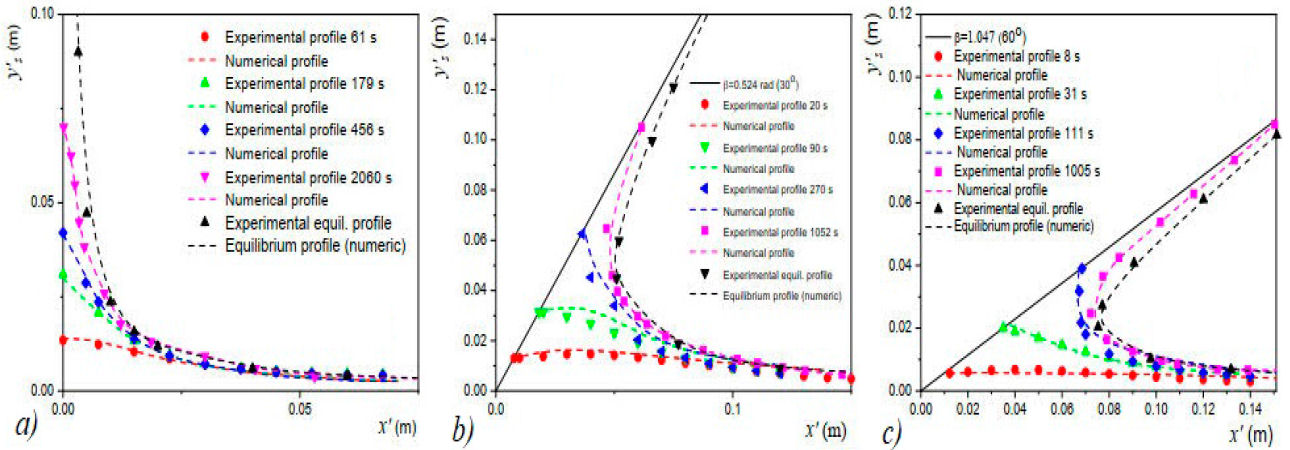
Figure 6 Numerically computed and experimentally obtained profiles for different time lapses during the capillary rise. The tilt angles are: a) β = 0 rad, b) β = 0.524 ± 0.002 rad (30o) and c) β = 1.047 ± 0.002 rad (60o). The aperture angles for each inclination are specified in the main text. The dashed curves represent the numerical solutions of Eqs. (12)-(17). Error bars and symbols are of the same size.
From comparisons between the experimental and numerical profiles, given in Fig. 6, we can establish that the numerical computations closely predict the evolution towards the equilibrium state of the free surfaces. The black-color dashed curves correspond to the numerical equilibrium profiles, which were obtained as in Fig. 5, i.e., one day after of the start-up of the capillary rise, having not observed any change of said equilibrium profiles. The shapes of the equilibrium profiles can also be obtained with Eq. (5) and none appreciable difference was found between the analytic and numerical profiles.
The location of the instantaneous height ys(t), for each tilt angle, is shown in Fig. 7. The numerical computations closely fit the experimental data. It can be noted that all data fit power laws of the form
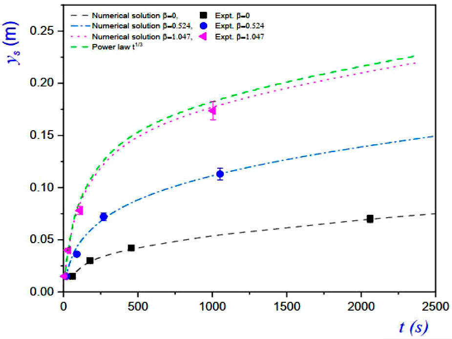
Figure 7 Plots of the time dependent heights ys(t), measured at the edges, for the three inclinations used in Fig. 6. The black, blue and magenta curves correspond to the numerical solutions of Eqs. (12)-(14) for various inclinations. Symbols in this plot match those for experimental data in Fig. 6. The green curve represents the power law
5 Conclusions
In this work, we have theoretically and experimentally analyzed the problem of the spontaneous capillary rise of viscous liquids in tilted Taylor-Hauskbee cells, with a particular case being the rise in vertical cells. In the theoretical treatment we used the rotation of coordinates to describe in a straightforward manner the equilibrium profiles and the dynamic evolution of the free surfaces, following the application of the Reynolds lubrication equations. We found self-similar asymptotic solutions for the meniscus elevation, at large values of time, which follows power laws of the form

