Research
Optics
Amplitude and phase measument using reflection polarization mode of a prism-based surface plasmon resonance
H. H. Sánchez-Hernándeza
J. M. Pérez-Abarcab
A. Santiago-Alvaradoc
A. S. Cruz-Félixd
aUniversidad del Papalopan, Loma Bonita, Oaxaca, México. e-mail: hehusan@unpa.edu.mx
bUniversidad del Papalopan, Loma Bonita, Oaxaca, México. e-mail: jperez@unpa.edu.mx
cUniversidad Tecnológica de la Mixteca, Huajuapan de León, Oaxaca, México. e-mail: santiago@mixteco.utm.mx
dUniversidad Tecnológica de la Mixteca, Huajuapan de León, Oaxaca, México. e-mail: sinue@mixteco.utm.mx
Abstract
In this paper, the amplitude and phase characteristics of internal reflection of gold nanofilms are investigated using polarization modulation of electromagnetic radiation in the Kretschmann geometry, an excited wavelength of the Surface Plasmon Resonance (SPR) at 633 nm is considered. The numerical results that are presented in this work are based on the substrate, the variation of the thickness of the dielectric and the type of plasmonic material using gold (Ag), through the ellipsometry parameters Ψ and Δ.
Keywords: Surface plasmon; polarization; ellipsometry; film thickness
1 Introduction
Recent advances in research and the construction of optical sensors make it possible to develop optical sensing platforms with outstanding optical properties [1,2,3]. Thus, a variety of optical methods have been applied in chemical sensors and biosensors including [4], spectroscopy (luminescence, phosphorescence, fluorescence, Raman), interferometry (white light interferometry, modal structure of optical waveguide interferometry) [5,6,7,8] and resonance of the optical waveguide surface plasmon (SPR)[9,
10]. In these sensors, a selected quantity is determined by measuring the refractive index, absorbance and fluorescence of the analyte molecules or a chemo-optical transduction [11].
SPR detection has advantages, such as high sensitivity, and on-site measurement may be possible. There are three methods for surface plasmon (SP) excitation: prism coupling, grating coupling, and waveguide coupling. Obviously, the challenge of measuring low concentrations with small molecules by SPR detection is the application related to the sharpness of the SPR curve that leads to substantial changes in reflectivity in the SPR absorption curve [12]. Also, the greater the sharpness, the greater the precision will be [13]. Sensor accuracy is the optimal difference that can be found between the actual measured value and the value indicated at the designed sensor output [14,15].
In this document, a new prism-based SPR design is proposed for the behaviour of the incident linear polarization state relative to the reflected polarization state. In addition, the excited wavelength of the SPR was also examined for better sharpness of the SPR at 633 nm. The investigation of the design was based on the substrate, the variation of the thickness of the dielectric and the type of plasmonic material using gold (Au), by means of the ellipsometry parameters Ψ and Δ.
2 Theoretical Model
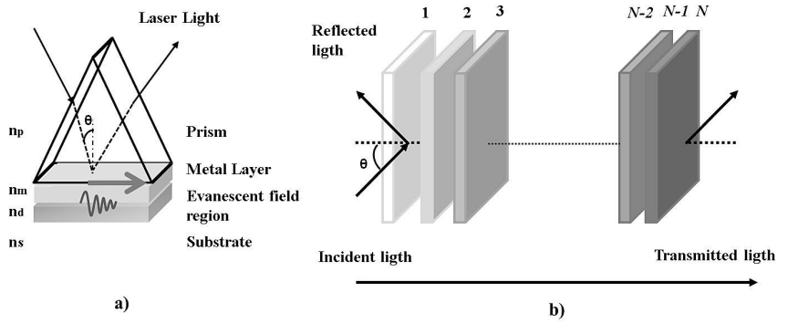
The theoretical model carried out to study the Kretschmann configuration for SPR is based on the principle of attenuated total reflection. In the prism case, the configuration consists of a high refractive index, a metal film thickness d
1, a low refractive index dielectric and a substrate Fig. 1(a). Most of the surface plasmon studies on noble metals are limited to Au and Ag, this is mainly because Au and Ag are much more stable and resistant. The application of more sophisticated spectroscopic techniques for the experimental determination of fundamental properties of surface plasmons for the excitation of the SPR, the Kretschmann configuration is often used [16]. In summary, a polarized ray of TM is directed at the base of a glass prism with an angle necessary for total internal reflection. A fine film is deposited on the base of a suitable metal. refractive index, n
m
metal film refractive index, n
d
dielectric refractive index and n
s
substrate refractive index.
The electric field couples with the oscillation of the charge density of electrons in the metal and excite a surface plasmon. The surface plasmon causes an evanescent field outside the film whose amplitude decays exponentially away from the surface metal. If an additional dielectric layer is incorporated on the metal film the incident light also excites the weakly guided modes in this waveguide structure. Both waveguide modes and SPR are observed simultaneously as a sudden drop in reflectivity. The configuration here consists of a glass prism (n
p
= 1.51) on which a gold film of dielectric permittivity ϵAu=-13.013+1.0331i [17,18] and a dielectric layer d
2 = 1.02 μm is deposited (n
d
= 2.13), where n is the index of refraction. The medium used on the transmission side is a substrate with (n
s
= 1,333) and the wavelength used is λ = 633 nm.
Both TE and TM polarization show waveguide modes of even first or zero order, respectively. A plasmon is observed only for TM polarization. The modes are excited, if the tangential component of the propagation vector matches the wave number in a guided mode. As the losses for waveguide modes are significantly lower, their dip is sharper compared to that of SPR. By exciting the dielectric, the dispersion of the modes changes and causes a change in the angle necessary for their excitation. Very high sensitivity can be expected if the overlap of the modal distribution with external stimuli is maximized.
In order to obtain the expression of the amplitude reflection coefficient for the incident beam polarization E
p
and polarization E
s
, the N -layer model [19] is considered, as shown in Fig. 1b). The N -layers model is widely used because it can be applied to a system containing any number of layers. Also, the calculations are easy, exact and precise, due to the absence of approximations. In the present work, N = 3 when only one metal layer is considered. The layers are considered to be stacked along the z-axis. The arbitrary medium layer is defined by the thickness d
j
of the dielectric constant ϵj, and the permeability μ
j
and the refractive index n
j
. The tangential fields in the first border Z = Z
1 = 0 are related to the previous ones with the final border Z = Z
N - 1
by:
U1V1=MUN-1VN-1,
(1)
where U
1 and V
1 are respectively the tangential fields of the electric and magnetic fields at the boundary of the first layer. U
N - 1
and V
n - 1
are the corresponding fields on the border of N-th layer. Here, M is known as the characteristic matrix of the structural combination and is given by:
M=∏j=2N-1MjM11 M12M21 M22,
(2)
with
Mj=cosβj -isinβj/qj-iqsinβj cosβj,
(3)
where
βj=2πλnjcosθj(zj-zj-1)=2πdjλ(ϵj-n12sin2θ1)1/2,
(4)
βj is the phase change found in the first discontinuity surface of the incident wave in the film and it is related to the wavelength λ, the thickness of the film d
j
, the complex refractive index of the film n
j
and the (complex ) refraction angle of the film. The value nj dj cosθj is the effective optical thickness of the film j for the refractive angle θj. Now, q
j
is the effective refractive index of the medium, substrate or film and is given by:
qj=cosθj/nj p-polarizationnjcosθj s-polarization,
(5)
so, it depends whether the incident light is polarized (parallel-p or perpendicular-s) respect to the incident plane. The angle θj is related to the incident angle θi and by Snell’s law:
nmsin(θi)=njsin(θj).
(6)
The reflectance intensity is:
Rp,s=|rp,s|2.
(7)
To examine the amplitudes and phases changes of the wave that is reflected obliquely and transmitted inside the film, the complex amplitude (parallel r
p
and perpendicular r
s
) is reflected obliquely and can be written in terms of their values and angles, as follows [20]:
rp=ρpeiϕp
(8)
rs=ρseiϕs,
(9)
ρp and ρs are the wave’s amplitudes attenuation, ϕp and ϕs represent the electromagnetic waves phases of the p-parallel and s-perpendicular components. The reflection coefficient of the intensity for polarized p-light and s-light are related to the elements of the characteristic matrix of the medium, evaluated from N=1 to the number of considered layers and that is given by [21]:
rp,s=(M11+M12qj)q1-(M21+M22qj)(M11+M12qj)q1+(M21+M22qj).
(10)
Finally, the light’s reflectance (R
p
) for the polarized light p, is:
Rp=|rp|2.
(11)
In general, (10) for a dielectric-film-substrate system represents two states of polarization (p and s) and they are the basis of ellipsometry. A change of polarization takes place at the reflection’s location due to the difference in attenuation amplitude and phase change experienced by the components p and s. The ratio of the incident and reflected polarization measurements can be represented by the following:
ρ=rprs.
(12)
The change in polarization after reflection from a surface can be represented as a complex reflection coefficient [22]:
ρ=tan(Ψ)e-iΔ.
(13)
So
tan(Ψ)=ρpρs,
(14)
also
Δ=ϕp-ϕs.
(15)
The right-hand side of (13) can be represented as a function f(n, k, d). In fact, the angles Ψ and Δ are obtained using ellipsometry measurements of the optical properties of a three-phase system, namely the refractive index of the medium n
1, the film n
2, the dielectric n
3, the substrate n
4 and also the film thickness d
1, the dielectric thickness d
2 for given values in the wavelength of the emitted beam and the angle of incidence θi in the medium. Now, this equation can be written the following way:
ρ=f(n1,n2,n3,n4,λ,d1,d2,θi).
(16)
The above equation can be divided into two equations for Ψ and Δ, like this:
Ψ=tan-1|f(n1,n2,n3,n4,λ,d1,d2,θi)|Δ=argf(n1,n2,n3,n4,λ,d1,d2,θi)
(17)
where |ρ| y arg(ρ) are the absolute values and the argument (angle of the complex function ρ).
3 Results and discussion
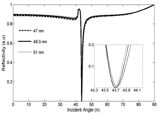
Initially, the gold film thicknesses suitable for the sensor based on the Kretschmann SPR configuration were simulated for thicknesses ranging from 47 to 51 nm for a wavelength of λ=633 nm applying the technique angular interrogation. Film parameters are compared with samples of certain thicknesses. MATLAB software was used for the analysis of the scanning parameter on the angle of incidence. Thus, it was performed in order to obtain the angle of the source capable of driving the SPR mode.
To characterize the behaviour of the sensor based on SPR of gold film in different thicknesses where the reflectivity is presented as a function of the angle of incidence, the SPR response curves are obtained by numerical analysis. Figure 2 shows the reflectivity as a function of the angle of incidence for the thin film of gold (Au) that varies from 47 to 51 nm, the sensing medium was air. The results show that for the gold film with a thickness of 49.6 nm the minimum reflectivity that is observed for the resonance of the surface plasmon with (R
min
= 3.53 × 10⁻⁶) is found at an angle of (θmin=43.69).
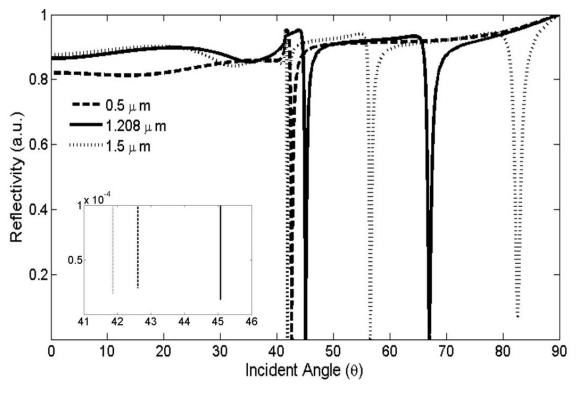
In Fig. 3, it is shown that different resonances for increasing values of dielectric thicknesses, when there is no substrate. Three sections can be perfectly distinguished: air at the top, dielectric in the middle, and the gold film at the bottom. The reflectivity decreases as the dielectric thickness increases, the minimum reflectance is found at 1.208 μm.
Figure 4 shows the reflectivity with different incidence angles against different values of the sensing layer’s refractive index, for metal thickness 49.3 nm and dielectric 1.02 μ m. For a given refractive index of the sensing layer, the curve shows different SPR dips at different angles.
In order to examine the reflectivity of the interface prism-substrate taking into account that the metal layer is covered with dielectric and external media water, then the angle of SPR dip minimum reflectivity for TM polarization is R
1 = 1.428 × 10⁻⁶, θ1=72.18. When the substrate (water) is deposited on the sensing part, there is a change in refractive index and it causes a displacement of the first dip for a resonance angle of 43.69 to 72.18, as can be observed in Fig. 5. Further, it is evident that the proximity of the resonance dip generates a mutual perturbation affecting the shape of the peaks. The SPR dips generated by the thin gold film covered with dielectric can be disturbed since the real and imaginary part of the dielectric constant of gold are higher than those of the silver.
The angles θ1'=arcsin(ns/np)=61.97
θ2'=arcsin(nd/np)=90 are the boundaries between the regions of the possible resonance phenomenon and are separated from the phenomenon based on the mode plasmon or the resonance of the waveguide.
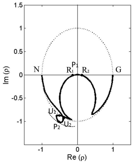
Figure 6 shows the d
2 = 1.208 nm constant-thickness contour of the ellipsometry function ρ in the complex plane for the prism-Au-dielectric-water system at λ=633 nm, this contour is traversed as the angle of incident θj is increased starting from the point N ρ=-1 when θ=0 (normal incident) and ending at the point G (ρ=1) when θ=90 (grazing incident).
The quantities describing classical measurement of the angles Ψ and Δ in the fundamental equation of ellipsometry (13) are plotted in Figs. 7 and 8 versus the angle of incident θj as we move along the d
2 = 1.208 μm constant thickness contour of Fig. 6. Several points are remarkable on the contour of Fig. 6 and on the curves Ψ and Δ of Figs. 7 and 8. Excluding the points N and G, these significant points are grouped as follows.
The points R
1,
R
2 of the contour of the Fig. 6 that intersect the real axis of the complex ρ plane occur at angles of incident θr1, θr2, depending on whether an intersection R
i
of the contour with the real axis is to the left or to the right of the origin Δ=π or 0, respectively. R
1 and R
2 for the d
2 = 1.208 μm contour shown in the Fig. 6 correspond to Δ=π and occur at angles of incident θr1=72.17, θr2=72.19, respectively. Such points are shown in the Fig. 8 as the intersections of the curve with the Δ=π (dotted line). When Δ=0 or π, incident light which is linearly polarized at any azimuth with respect to the plane of incidence is also linearly polarized after it is reflected from the film coated substrate. This is the basis of the polarized surface suppression analyzer.
At the intersection of points U
1 and U
2 with the unit circle of the complex ρ-plane, we have tanΨ=1, hence Ψ=45∘, these points are shown in the Fig. 7 (dotted line). When tanΨ=1, we have |Rp|=|Rs| and ρ= e-iΔ, the film-substrate system acts as reflection retarder. Such a retarder exhibits isotropic absorption because of the absolute reflectances R=|Rp|2=|Rs|2 are necessarily less than 1. For the substrate-film system with d
2 = 1.208 μm at wavelength of λ=633 nm, the angles of incidence which act as retarder are achieved at θu1=60.603∘ and θu2=62.132∘, the associated delays are ΔU1=246.21∘ and ΔU2=241.105∘, whereas the reflectances are RU1=0.881 and RU2=0.913.
The points P
1 and P
2 show the minimum-radius and maximum-radius circles, centred on the origin and touch the contour, respectively. These two concentric circles define an annular domain, in which the contour is confined. At P
1 and P
2, ρ=tanΨ is minimum and maximum, respectively. These points indicate how a given film-substrate system come close to act as a p or s-suppressing polarizer. When the minimum radius is zero, Ψ=0∘, the contour passes through the origin. At the corresponding angle of incidence θP1 the film-substrate system acts exactly as a p-suppressing polarizer. On the other hand, when the maximum radius becomes infinitely large, Ψ=90∘, the contour passes through the point at infinity. At the corresponding angle of incidence θP2, the film-substrate system acts exactly as an s-suppressing polarizer.
4 Conclusions
A novel and simple method to generate a theoretical investigation prism-based SPR sensor was proposed. In our study we analyzed the refractive index and reflectivity. The SPR sensor structure was composed by a prism coated with metal film (Au), a dielectric and external sensing medium. For a given refractive index of the sensing layer, the curve shows different SPR dips at different angles. Once the sensing part of the dielectric is deposited (water), the changes in the external refractive index of the metal film produce a displacement of the first dip of the resonance angle. Several points are remarkable on the contour of the ellipsometry function ρ in the complex plane and on the curves Ψ and Δ. The points R1,R2 of the contour that intersect the real axis of the complex ρ plane which occur at angles of incident θr1, θr2, show the bases of the polarized surface suppression analyzer. The points U
1 and U
2 intersect the unit circle of the complex ρplane, at such intersections we have: |Rp|=|Rs| and ρ= e-iΔ, the film-substrate system acts as reflection retarder. The points P
1 and P
2 associated with the minimum-radius and maximum-radius circles centred on the origin, touch the contour. These points indicate how a given film-substrate system come close to operating as a p or s-suppressing polarizer.
References
[1] M. Piliarik and J. Homola, Surface plasmon resonance (SPR) sensors: approaching their limits?, Opt. Express 17 (2009) 16505, https://doi.org/10.1364/OE.17.016505.
[ Links ]
[2] J. Homola, Surface Plasmon Resonance Sensors for Detection of Chemical and Biological Species, Chem. Rev. 108 (2008) 462, https://doi.org/10.1021/cr068107d.
[ Links ]
[3] Z. Chen, L. Liu, Y. He and H. Ma, Resolution enhancement of surface plasmon resonance sensors with spectral interrogation: resonant wavelength considerations, Appl. Opt. 55 (2016) 884, https://doi.org/10.1364/AO.55.000884.
[ Links ]
[4] U. Pant, S. Mohapatra and R. S. Moirangthem, Total internal reflection ellipsometry based SPR sensor for studying biomolecular interaction, Materials Today: Proceedings 28 (2020) 254, https://doi.org/10.1016/j.matpr.2020.01.602.
[ Links ]
[5] R. Singh, P. Thakur, A. Thakur, H. Kumar, P. Chawla, J. V. Rohit, R. Kaushik and N. Kumar, Colorimetric sensing approaches of surface-modified gold and silver nanoparticles for detection of residual pesticides: a review, International Journal of Environmental Analytical Chemistry 101 (2021) 3006, https://doi.org/10.1080/03067319.2020.1715382.
[ Links ]
[6] K. M. Mayer and J. H. Hafner, Localized Surface Plasmon Resonance Sensors, Chemical Reviews 111 6 (2011) 3828, https://doi.org/10.1021/cr100313v.
[ Links ]
[7] S. M. Fothergill, C. Joyce and F. Xie, Metal enhanced fluorescence biosensing: from ultra-violet towards second near-infrared window, Nanoscale, The Royal Society of Chemistry 10 (2018) 20914, https://doi.org/10.1039/C8NR06156D.
[ Links ]
[8] J.-F. Li, C.-Y. Li and R. F. Aroca, Plasmon-enhanced fluorescence spectroscopy, Chem. Soc. Rev. 46 (2017) 3962, https://doi.org/10.1039/C7CS00169J.
[ Links ]
[9] M. Piliarik, H. Vaisocherová and J. Homola, Surface Plasmon Resonance Biosensing, Biosensors and Biodetection 503 (2009) 65, https://doi.org/10.1007/978-1-60327-567-5_5.
[ Links ]
[10] A. K. Sharma, R. Jha and B. D. Gupta, Fiber-Optic Sensors Based on Surface Plasmon Resonance: A Comprehensive Review, IEEE Sensors Journal 7 (2007) 1118, https://doi.org/10.1109/JSEN.2007.897946.
[ Links ]
[11] A. Brecht and G. Gauglitz, Optical probes and transducers, Biosens Bioelectron 10 (1995) 923, https://doi.org/10.1016/0956-5663(95)99230-i.
[ Links ]
[12] J. Homola, S. S. Yee and G. Gauglitz, Surface plasmon resonance sensors: review, Sensors and Actuators B: Chemical 54 (1999) 3, https://doi.org/10.1016/S0925-4005(98)00321-9.
[ Links ]
[13] A. A. Alwahib, Sura H., Al-Rekabi and W. H. Muttlak, Comprehensive study of generating sharp dip using numerical analysis in prism based surface plasmon resonance, AIP Conference Proceedings 2213 (2020) https://doi.org/10.1063/5.0000103.
[ Links ]
[14] K. D. Izquierdo, A. Salazar, A. Losoya-Leal and S. O. Martinez-Chapa, A computer model for the prediction of sensitivity in SPR sensing platforms, Pro. SPIE Plasmonics in Biology and Medicine XII 9340 (2015) 53, https://doi.org/10.1117/12.2079684.
[ Links ]
[15] G. Xia, C. Zhou, S. Jin, C. Huang, J. Xing and Z. Liu, Sensitivity Enhancement of Two-Dimensional Materials Based on Genetic Optimization in Surface Plasmon Resonance, Sensors (Basel) 19 (2019) 1198, https://doi.org/10.3390/s19051198.
[ Links ]
[16] A. A. Kolomenskii, P. D. Gershon and H. A. Schuessler, Surface-plasmon resonance spectrometry and characterization of absorbing liquids, Appl. Opt. OSA 39 (2000) 3314, https://doi.org/10.1364/AO.39.003314.
[ Links ]
[17] K. M. M cPeak, S. V. Jayanti, S. J. P. Kress, S. Meyer, S. Iotti, A. Rossinelli and D. J. Norris, Plasmonic Films Can Easily Be Better: Rules and Recipes, ACS Photonics 2 (2015) 326, https://doi.org/10.1021/ph5004237.
[ Links ]
[18] P. B. Johnson and R. W. Christy, Optical-constants of noble-metals, Phys. Rev. B 6 (1972) 4370, https://doi.org/10.1364/OE.19.000107.
[ Links ]
[19] C. Zhou, G. Xia and G. Wang, Eff
ect of Spectral Power Distribution on the Resolution Enhancement in Surface Plasmon Resonance, Photonic Sens 8 (2018) 310, https://doi.org/10.1007/s13320-018-0507-8.
[ Links ]
[20] M. Born and E. Wolf, Principles of Optics, 7th ed., New York: Pergamon Press (1980) pp. 1.
[ Links ]
[21] A. K. Sharma and B. D. Gupta, On the sensitivity and signal to noise ratio of a step-index fiber optic surface plasmon resonance sensor with bimetallic layers, Opt. Commun 245 (2005) 159, https://doi.org/10.1016/j.optcom.2004.10.013.
[ Links ]
[22] R. M. Azzam and N. M. Bashara, Ellipsometry and Polarized Light, Amsterdam: North-Holland (1977).
[ Links ]


 text new page (beta)
 English (pdf)
 Article in xml format
 Article references
 Send this article by e-mail
 Cited by SciELO
  Similars in
SciELO
Similars in
SciELO 
 Permalink