


 text new page (beta)
 English (pdf)
 Article in xml format
 Article references
 Send this article by e-mail
 Cited by SciELO
  Similars in
SciELO
Similars in
SciELO 
 Permalink
1.Introduction
The invention and development of new techniques for fabricating semiconductor nanostructures 1-5 have made it possible to design quantum wells, quantum well wires and quantum dots of various cross-sections. Of these, one semiconductor material that has been of great interest for device application is Gallium Arsenide (GaAs). The GaAs has been studied extensively both experimentally and theoretically 6-14. These studies have been directed towards determining its potential for optical and electronic device applications. In this regard, the GaAs quantum well dot is of particular interest. This is, essentially, an object with zero spatial dimensions. The quantum well dot comes in cylindrical, rectangular, triangular and, some other quite esoteric geometries. Studies have been carried out on donor impurity binding energies in GaAs quantum wells 14,15, quantum well wires 16 and quantum dots 17-19. Further work has seen the use of the binding energies to compute density of impurity states 9 and photoionization cross-sections 20-26 when the system is subjected to external constraints. In our previous work 26, we have studied the effect of Hermanson’s spatial dielectric function, finite and infinite barrier potentials and axial lengths on the photoionization cross-section of a hydrogenic and a non-hydrogenic donor impurity in a GaAs quantum well dot (QWD) of circular cross-section. We found that the photoionization cross-section of the hydrogenic donor impurity is much larger than that of the non-hydrogenic donor impurity in the same frequency range and in the finite and the infinite barrier potential regimes.
In the present work, we have considered a hydrogenic donor impurity located at different axial positions in a GaAs quantum dot (QD) of cylindrical geometry. We have carried out a theoretical study of the variation of the photoionization cross-section of the donor impurity with incident photon frequency, the location of the donor impurity along the axis of QD and applied uniaxial stress. In the study, we calculated the donor impurity binding energies as functions of the location of the donor impurity along the axis of the QD, incident photon frequency and applied uniaxial stress. We then used the binding energies to calculate the photoionization cross-sections of the donor impurity when the system is subjected to various incident photon frequencies, applied uniaxial stress and for various locations of the QD axis. In our calculations we have used a variational technique within the effective mass and dipole approximations 26,27. It should, however, be noted that other works 28-30 have employed other techniques such as spin density functional theory instead of the variational technique to carry out similar studies. We have assumed that a Ga 1−x Al x As matrix surrounding the GaAs QD provides an infinite potential barrier.
Our work is organized as follows: In Sec. 2 we present the theoretical framework, while in Sec. 3 we present the results and discussions. Finally, in Sec. 4 we give our conclusions.
2.Theoretical model
2.1.Hydrogenic Donor Impurity
The Hamiltonian for a hydrogenic donor impurity which is located along the QD axis is given by
where, m * (P) is the stress dependent effective mass of the donor impurity in the QD and ε(P) is the stress-dependent dielectric function. The position of the donor impurity is given by
In Eq. (1),
where m e is the mass of the free electron 31-33, E P Γ = 7.51 eV is the energy related to the momentum matrix element, Δ 0 = 0.341 eV is the spin-orbit splitting energy. E P Γ is the uniaxial stress-dependent energy gap for GaAs QD semiconductor at the Γ-point in units of eV 34.
where a= 1.425 eV, b= 1.26×10⁻² eV/(kbar), c= −3.77×10⁻⁵ eV/(kbar)2 and E P Γ (0)=1.519 eV is the energy gap for the GaAs QD at the Γ-point when the uniaxial stress is P= 0 kbar. In Eq. (1), the stress-dependent dielectric constant is given by 31-33
where, ε(0)=12.56 is the static dielectric constant of GaAs,13 and δ= −1.73×10⁻³ kbar.
In Eq. (1),
is the barrier potential which confines the donor impurity within the quantum dot. In this equation, L z (P) is the stress-dependent length of the QD and V 0 (P) is the barrier height as a function of the applied stress. These are given by,
and
where in Eq. (7), S 11 = 1.16×10⁻³ (kbar)−1 and S 12 = −3.7×10⁴ (kbar)−1 and L z (0) is the unstrained length of the QD. In Eq. (8), Q c = 0.658 is the band offset parameter, while ΔE g Γ (x,P) is the band gap difference between the QD material and the barrier material and is given by
here in the above equation, ΔE g Γ (x)=(1.15x+ 0.37x 2 ) eV gives the variation of energy gap difference in the absence of the applied stress, while the quantity D(x)=[−(1.3×10⁻³)x] eV/kbar is the stress coefficient of the band gap. Our trial wave function for the hydrogenic donor impurity in its ground state is given by
Thus, the kinetic energy is found as follows,
where, H T is the kinetic energy part of the Hamiltonian given in Eq. (1).
The kinetic energy of the donor impurity is thus obtained as,
The potential energy for the hydrogenic donor impurity is given by
Thus, the total energy of the donor impurity is given by
2.2.The total energy of the donor in the excited state
The Hamiltonian of the hydrogenic donor impurity in the final state to which the donor is excited is given by
and we have taken the wave function for the donor impurity in this state to be
but in this state, k= 0 in the first excited state. Hence the total energy of the donor impurity in this state is
where ∫Ψ f * ΨdV = 1 is the normalization condition which yields
From Eqs. (16) and (17), the total energy of the excited state is found to be
The minimum energy, E min of the donor impurity is obtained from the expression in Eq. (14), subject to the minimization condition
The binding energy of the donor impurity is then obtained from the Eqs. (14) and (19). Thus,
2.3.Non-hydrogenic donor impurity
The Hamiltonian for the non-hydrogenic donor impurity is given by
and the stress-dependent spatial dielectric function is given by
where, δ= −1.73×10⁻³ kbar−1 and,
is the Hermanson’s spatial dielectric function 35 with c= 5.38×10⁻²¹ nm−1.
The static dielectric constant was taken to be ε(0)=12.56 13.
The Hamiltonian for the non-hydrogenic donor impurity now has an additional term, ΔV, in the potential energy operator due to the spatial dielectric function ε(ρ,z). Here we have also used the same trial wave function as for the hydrogenic donor impurity case. Thus,
where V h is given by Eq. (13) and ΔV is a perturbative term due the spatial dielectric function and is given by
or
The total energy of the non-hydrogenic donor impurity is thus given by
The minimum energy, E total,n−h , for the nonhydrogenic donor impurity is obtained by minimizing the above expression with respect to the variational parameter λ.
2.4.Binding energy and photoionization cross-section
In both hydrogenic and non-hydrogenic cases, the binding energy is obtained by subtracting the respective minimum energy from the free energy. The binding energy is then used to obtain the photoionization cross-section from
In Eq. (28), ⟨Ψ f | is the final state into which the donor impurity is excited, |Ψ i ⟩ is the ground state trial wave function of both the hydrogenic and non-hydrogenic donor impurities, whichever is the case in the calculation. The constants n and ε are the refractive index and dielectric constant of the GaAs QD material, respectively, and ξ eff is the effective electric field of the incoming radiation on the donor impurity, while ξ 0 is the average field in the medium. In practice, it is not easy to determine ξ eff , hence the effective field ratio ξ eff /ξ 0 is used in the calculation of photoionization cross-section. Since the ratio is not known to affect the shape of the photoionization cross-section, it is generally set equal to unity 36.
In addition, φ=e
2
/ℏc is the fine structure constant. The term
Furthermore, in Eq. (28),
where Γ= 0.1R * is the donor impurity linewidth. Here, R * ≈ 5.25 meV is the effective Rydberg energy.
3.Results and discussion
In this section we present our results and discuss their implications. In Fig. 1, we show the variation of the photionization cross-sections of an on-center hydrogenic donor impurity in a cylindrical QD with incident photon frequency for quantum dots of axial lengths, L z = 10, 20, 30, 40 and 50 nm. We observe that, for all the axial lengths and constant radius of the QD, the photoionization cross-section rises from some miminum ranging from σ(ω)=1.78 × 1015 cm2 at f= 1.4×10¹² Hz to a maximum of σ(ω)=4×1015 cm2 at f= 1.7×10¹² Hz for L z = 10 nm (the solid, red curve), from a minimum of σ(ω)=10×1015 cm2 at f= 1.4×10¹² Hz to a maximum of σ(ω)=23.5×1015 cm2 at f= 1.8×10¹² Hz QD length of L z = 50 nm (dash-dotted, black curve) for the largest photoionization cross-section. It can also be observed that all the peaks of the photoionization cross-sections cluster around an incident frequency of about f= 1.8×10¹² Hz. Thereafter, the photoionization cross-sections decrease steeply at first and then gradually to some constant values which are close to each other as the incident photon frequency increases beyond f= 4.2×10¹² Hz . It seems that the photoionization cross-section becomes less sensitive to further increase of incident photon frequency beyond this particular frequency regime.
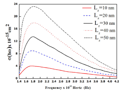
FIGURE 1 Variation of photoionization cross-section of an on center shallow hydrogenic donor impurity in a cylindrical quantum well dot with incident photon frequency for quantum dot side lengths Lz = 10, 20, 30, 40 and 50 nm.
In Fig. 2, the variation of the photoionization cross-section of an on-center hydrogenic donor impurity with uniaxially applied stress for a range of incident photon frequencies is shown. Specifically, we have used for the applied stress, P= 0, 10, 20, 30 kbars on a QD of constant length of 10 nm. We observe that for the same frequency range, the photoionization cross-sections of the donor impurity increase from a low value to a peak and then it decreases as the frequency increases beyond f= 2.0×10¹² Hz until it reaches a constant value from about f= 4.2×10¹² Hz. From this frequency and beyond, the photoionization cross-section appears to be independent of the frequency. It is also noted that for the same QD length, the photoionization increases with decreasing applied stress. For example, the peak of thephotoionization cross-sectionof thedonor impurity with no applied stress is almost four times that for P= 30 kbar at almost the same frequency.
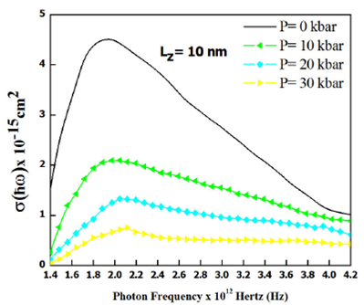
FIGURE 2 Variation of photoionization cross-section of an oncenter shallow hydrogenic donor impurity with incident photon frequencies for four constant values of uniaxial stress, P = 0, 10, 20, and P = 30 kbars applied along the z axis of the quantum dot; and for quantum dot side length Lz = 10 nm.
From Fig. 3, it is observed that for a constant length of L z = 20 nm, the photoionization cross-sections follow the same trend observed for L z = 10 nm, except that the photionization cros-sections are much larger with the highest peak reaching σ(ω)=9 × 10⁻¹⁵ cm2 for P= 0 kbar and σ(ω)=4.3×10⁻¹² cm2 for P= 10 kbar. These values of the cross-sections are almost twice the values observed for the QD of length L z = 10 nm. Figure 4 also shows the same trend observed for Figs. 2 and 3, i.e., that as the length of the QD increases, with other parameters kept constant, the photoionization cross-section are much larger for P= 0 kbar and decreases with increasing applied stress for constant QD size. This means that applied stress suppresses the photoionization cross-section of the donor impurity.
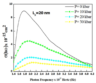
FIGURE 3 Variation of photoionization cross-section of an oncenter shallow hydrogenic donor impurity with incident photon frequencies for four constant values of uniaxial stress, P = 0, 10, 20, and P = 30 kbars applied along the z axis of the quantum dot; and for quantum dot side length Lz = 20 nm.
In Fig. 5, we compare the effect of applied uniaxial stress of P= 30 kbar on the photoionization cross-section for both hydrogenic and non-hydrogenic donor impurity on a QD of length L z = 50 nm and radius r= 5 nm. Initially, there is no difference on the photoionization cross-sections for the hydrogenic and non-hydrogenic donor inpurities with incident photon frequency until about f= 1.5×10¹² Hz when there is a clear difference in the effect of the applied stress to the photoionization cross-sections with the effect being more pronounced in the non-hydrogenic case than in the hydrogenic case. This effect on the cross-section reaches its peak at about f= 1.7×10¹² Hz. Thereafter, the photoionization cross-sections decrease gradually towards some minima at which any further increase in incident photon frequency does not affect the photoionization cross-section.
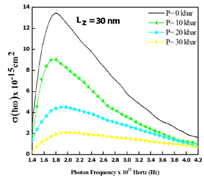
FIGURE 4 Variation of photoionization cross-section of an oncenter shallow hydrogenic donor impurity with incident photon frequencies for four constant values of uniaxial stress, P = 0, 10, 20, and P = 30 kbars applied along the z axis of the quantum dot; and for quantum dot side length Lz = 30 nm.
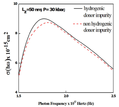
FIGURE 5 Variation of photoionization cross-section of an oncenter shallow hydrogenic donor impurity and non hydrogenic donor impurity with incident photon frequencies for a fixed value of uniaxial stress, P = 30 kbar applied along the z axis of the quantum dot; and for quantum dot side length Lz = 50 nm.
Finally, in Fig. 6, we present the plots of the photoionization cross-sections for two donor impurity positions along the z-axis and with incident photon frequency varying from f= 1.5×10¹² Hz to f= 2.5×10¹² Hz for a constant applied uniaxial stress P= 30 kbar, and for a QD of radius r= 5 nm, and length L z = 50 nm. We observe that for on center donor impurities, the photoionization cross-sections of the hydrogenic and non-hydrogenic donors are close to each other while for the donor impurities located at z i = 25 nm, the photoionization cross-section of the hydrogenic donor impurity is much greater than that of the non-hydrogenic one throughout the frequency range considered.

4.Conclusions
We have used a variational technique within the effective mass approximation to study the variation of the photoionization cross-section of a hydrogenic and a non-hydrogenic donor impurity in a GaAs quantum dot with incident photon frequency and applied uniaxial stress. The quantum dot is of a cylindrical geometry and the donor impurity is located at various positions along the axis of the quantum dot. In our study, we have observed that for both hydrogenic and non-hydrogenic donor impurity the photoionization cross-section increases rapidly with incident photon frequency from some low value, up to a peak of about the same cluster of frequency then it decreases with further increase in frequency up to a point where the photoionization is no longer sensitive to the incident photon frequency. This is true for all positions of the donor impurities and lengths of the QD we studied.
However, the photoionization cross-sections for longer QD are much larger than those for smaller QDs in both the hydrogenic and non-hydrogenic donor impurity cases. We have observed that the applied uniaxial stress depresses the photoionization cross-sections in both hydrogenic and non-hydrogenic donor impurity cases. Importantly, the photoionization cross-sections for the hydrogenic donor impurity are larger than for the non-hydrogenic donor impurity for the same incident photon frequencies, QD size, and same applied uniaxial stress. The study has, therefore, shown that the photoionization cross-sections of hydrogenic and non-hydrogenic donor impurities are different for the same quantum dot size, the same incident photon frequencies, and same applied uniaxial stress. Furthermore,the larger the QD, the larger is the photoionization cross-section. It is our conclusion that when designing thermo-electronic and opto-electronic devices using GaAs QDs one should take into consideration the frequency at which the photoionization is optimum, whether or not the donor impurity is of hydrogenic or non-hydrogenic type. Consideration should also be taken of the stresses to which the device will be subjected to, for example, a device which will be used in a fighter aircraft will be subjected to very high and sudden g-forces and hence must be robust enough to withstand these forces.

