


 text new page (beta)
 English (pdf)
 Article in xml format
 Article references
 Send this article by e-mail
 Cited by SciELO
  Similars in
SciELO
Similars in
SciELO 
 Permalink
1. Introduction
The Instituto Nacional de Investigaciones Nucleares (ININ) Tandem Van de Graaff accelerator provides different ion beams for fundamental research[1,2]. During its lifetime the machine has experienced several upgrades to improve the beam intensity, including the change of the ion source, and others main systems[3,4].
All these changes have left uncertainty in the evolution of the beam parameters (emittance, divergence, and brightness) along the Tandem, limiting the beam transmission to the experimental areas, and due to this uncertainty, it is complicated to assign the origins of the beam losses.
An intense beam dynamics study taking into account measurements and simulations needs to be performed to take advantage of all the machine capabilities using the new systems and mitigate the operation problems adequately[5], to finally achieve more precise measurements in the experimental areas.
As a first step, the research in this work will be focused on the ion source and low energy beam line, specially in the beam formation conditions with the aim of improve the overall machine performance
2. Experimental Setup
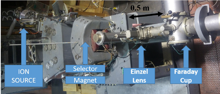
The Source of Negative Ions by Cesium Sputtering source (SNICS)[6] is coupled to an electrostatic accelerator tube at 40 kV. A drift region connects this low energy acceleration stage to a 20° dipole magnet where the removal of electrons and the selection of the ion specie is achieved (see Fig. 1), then the Einzel lens focus the resulting beam, and it is monitored using a Faraday cup and a scintillator screen.
In the acceleration stage, the accelerator tank reaches a maximum potential of 6 MV,
and it is applied to a series of electrodes with a helical pattern for beam focus
and acceleration. Half-way through the acceleration stage, the negative ions are
stripped to positive ions by carbon films, with a target thickness of 10
After the acceleration tank, a quadrupole system focuses the beam before it enters in the electromagnet (close to 1.0 T) where the ion energy is selected with a resolution in the order of KeV. Finally, the beam position is corrected before a horizontal dipole selects the beamline for the experiment.
2.1 Ion Source
Even though the production of negative ions is not well understood. It is used reliably to produce negative beams all around the world, and the SNICS ion source is an excellent example of it[7].
To produce the beam the SNICS uses Cesium (Cs) as a catalyst where the beam
formation is driven by Cs
To create the appropriated Cs layer, a treatment of Cs vapors from an external heated Cs reservoir is applied with the aim of spread it into the cathode target and ionizer surfaces.
The ionizer is heated close to 1000°C (using a heating power between 125 and 135
W) and the neutral Cs in the ionizer surface is heated until been positively
ionized. Then the Cs
Each charged particle generated in the target does need different conditions for the beam formation, the cathode-anode voltage is tunable to a maximum of 8 kV to find the best operation condition.
The target preparation also plays an essential role in the beam production, each time that the cathode holder is changed and set in place, the beam conditions change even when the beam to be generated is the same. This phenomenon will be investigated in later sections.
3. Simulation parameters
The Ion Beam Simulator (IBSIMU)[10] Y is a 3-D program used to simulate extraction systems and beam dynamics in the low energy beam transport systems. The simulations for this work take into account the electric field map generated by the electrodes potential distribution (Fig. 2) and the space charge produced by the charged particles traveling within the system, both contributions are combined solving the Vlasov equation (Eq. 1) by finite differences,
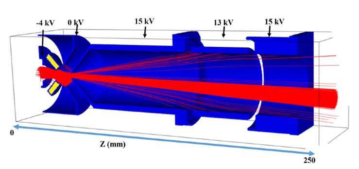
FIGURE 2 Extraction system and ion source simulation in IBSIMU including the beam (red), Cs ionizer (yellow), and electrodes (blue).
where
3.1 Extraction system and beam transport
A set of simulations were performed to study the maximum beam current transmission in the extraction system and beamline using the code TRAVEL[11] taking as input the ion source simulation output. The beam was tracked through the beamline including the 20° selector magnet up to the Faraday cup where a direct comparison between measurements and simulation was made (see Fig. 1).
The measurements and simulations suggest that not important ion beam losses (the electrons are lost in the magnet) had been observed once the focal elements are appropriately set. This allow us to be confident that the beam recorded at the Faraday cup will match the ion source transmission.
The simulations suggest that the beamline simplicity preserves the emittance but limits the control in the beam parameters at the entrance of the accelerator tank for an appropriated matching. Another importan result from the simulations is that only for beam intensities close to 1 mA the beam space charge produce important beam losses.
4. Ion Source Simulations
The first ion source simulations were using a similar approach to other works[12]: an approximately Gaussian beam is generated in the target then it is tracked through the extraction system and beamline as Fig. 2 shows.
Using this simulation method for H
The previous results suggest that the beam space charge is not the source of the problem in the beam transport, because these beam intensities are well above the maximum obtained in the accelerator measurements.
Using maximum intensities from the measurements as input for the simulations, the behaviour is not the same. Once the anode cathode voltage is above 2 kV, we reach full transmission in disagreement with the measurements (Fig. 3).

After looking into the beam generation parameters without success, it was clear that
this simulation method was not good enough to reproduce the beam behavior in the ion
source. Therefore, we decided to take a more realistic approach for the beam
generation, by including the Cs
5. Cs Ionizers geometries
In the ININ SNIC ion source, two ionizers have been used to generate negative beams; a Solenoidal Antenna Ionizer (SAI)[7] and a Conical Ionizer (CI)[13], both are heated by an external power source to produce the Cs. Due to the low beam intensity delivered by the source using the SAI, it was necessary to change it for the CI to produce more beam[14].
The origin of the low beam intensity in the SAI was never clear, reason why will be studied, even when it has been replaced.
To accurately model the ion source and implement the Cs
The new simulations also include the secondary electrons (not included in the figures
for clarity) and ion production by the impact of the Cs ions into the surfaces[17]. The Fig.
4 shows the ionizer producing the Cs
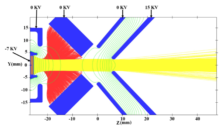
FIGURE 4 IBSIMU simulation of the SNIC ion source Cs+ (red), negative ion beam (yellow), and electrodes (blue).
The current ratio yield
Taking in to account the Faraday cup measurements and the yield ratio, with the
cathode-anode voltage at 7 kV the ionizer produced up to 1 mA of Cs
In the next section, we study both geometries to find the operating limits and how to achieve higher intensities.
5.1 Solenoidal Antenna Ionizers
During the ion source operation with the SAI, it produces uniform beams at
intensities below 1
Due to the lack of tools to simulate and study such complex system, it was assumed that the irradiation on the SNICS surfaces produces a vacuum problem triggering the stripping losses.
The erosion pattern in the cathode used for beam production in high and low intensity shows some differences. The high-intensity beams end with a convex cathode surface and the ones used for the low-intensity end with a flatter surface using the same anode-cathode voltages giving a hint about the role of the Cs space charge.
Using the simulations we found that in the low intensity cases (less than 0.1 mA
of Cs
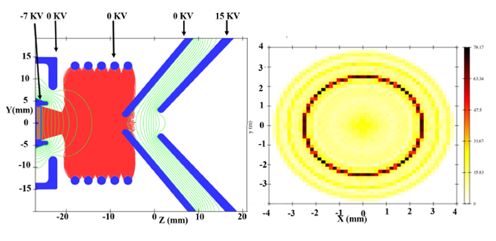
FIGURE 5 IBSIMU simulation of the SNIC SAI ionizer with Cs+ emission irradiating the cathode target (left), and the irradiation profile (right).
The profile of the Cs
As the Cs
Unfortunately the Cs
This hollow irradiation together with the small anode aperture (3 mm) produce a beam that can be stopped almost entirely in the anode electrodes and the SAI ends with less beam production even when the ionizer produces more ions.
The total space charge deposition (SCD) of all the ions involved in the
simulation can be estimated with the Eq. [eq:scharg][16], where
The previous results show that the longitudinal length of the SAI is not the optimum for the beam production. Using the same simulations it was found that by removing the closest turn to the cathode it is possible to extract more ions from the back of the antenna and achieve a centered irradiation. In consequence a new antenna with fewer turns is under design to avoid the screening problem in the high-intensity cases.
5.2 Conical Ionizer
The current ionizer used at the ININ ion source has a conical geometry, it also comes with a new configuration of the anode electrode where the aperture is twice as before. This change allows a higher transmission for bigger beam sizes, allowing the production of higher intensities than the previous ionizer configuration.
After the beam operation, the ionizer produces a concave surface at the cathode,
indicating how the Cs
Previous works that use 2-D simulations[17,18] of this system have
shown, they have shown, how the conical ionizer concentrates 90
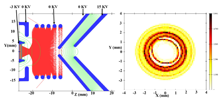
FIGURE 6 IBSIMU simulation: Suppression of the Cs+ emisión at the Solenoid ionizer surface due to space charge screening (left), and the irradiation profile at the cathode surface (right).
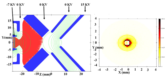
FIGURE 7 IBSIMU simulation: Conical Ionizer producing Cs beam (red) to irradiate the cathode (left) and the irradiation profile at the cathode surface (right).
The 3-D approach reveals how the irradiation peak at 7 kV is not in the cathode center, and instead it is allocated in a 0.4 mm circle due to Cs overfocusing, this result has profound implications for the beam intensity and quality[19], limiting also the maximum voltage to set.
To achieve an uniform target irradiation and eliminate the empty spot in the
cathode center (Fig. 7), we change the Cs
Another unexpected deficiency revealed by the simulations, consist that in the back part of the cylinder, the anode-extractor voltage suppresses the Cs emission contributing to the hollow irradiation in the cathode, limiting the maximum extractor voltage. By decreasing the extractor voltage or by closing the anode electrode aperture this effect can be suppressed.
Measurements have shown how the Cs irradiation intensity at the cathode increases
by 10
For the maximum beam transmission in to the Faraday cup, the beam has a halo
component that covers all the beampipe. This halo is a product of the
irradiation outside the 2 mm spot which is less than 5
Comparing the new simulation approach to the measurements (Fig. 8), we have a better agreement that confirms that it is
necessary to take in to account the Cs

5.3 Target position
Using the conical ionizer we studied the role of the distance between the cathode and the ionizer in the beam generation. By design, it is suggested to place target surface sunken 2 mm in relation to the cathode holder, until now the effect of the target position and its impact in the beam dynamics for this source was not clear.
Typically, to maximize the cathode lifetime, this is filled to the top and due to
the sputtering effect there is a continuous change in the location where the
beam is generated (to deliver 2
In the Faraday cup the beam current decays as the cathode target is worn out, making it necessary to renew the targets to recover the beam intensity. In some cases, after a cathode renovation the current may fall below what the old cathode produced.
To simulate errors in the target preparation and the wear by sputtering, we
changed the cathode target position getting a maximum H
The Fig. 9 shows the correlation between the
target position, anode voltage and transmission. Within
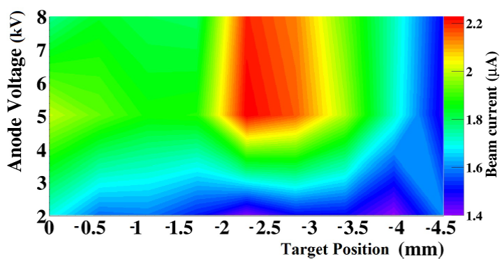
FIGURE 9 Negative Beam current recorded at the end of the extractor as function of the target position within the cathode container.
The simulations and the Fig. 9 also suggest
that it is necessary to tune the anode electrodes as the target sinks into the
cathode holder, to properly focus the Cs
For new targets, if it is sunken less than 1 mm into the holder edge (Fig. 10), the beam divergence increases, producing beam losses or even damages on the ionizer surface.
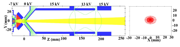
FIGURE 10 IBSIMU simulation: H - (yellow) and Cs+ (red) trajectories (left) and beam profile at the end of the extraction system (right) for the Cathode target in line with the electrodes.
One positive aspect of the beam collimation on the electrodes is the beam emittance reduction at the end of the extraction system, obtaining 1 mm mrad emittance comparing to the 5 mm mrad for the source delivering the same current once the cathode is sunken 2 mm.
6. Conclusions
A comparison between measurements and 3-D simulations has been made in the SNICS source and transport to understand some operation problems towards the increase of the beam intensity.
The standard simulation method where a Gaussian beam distribution is used to generate the beam in the cathode surface, it is not good enough to reproduce the beam measurements.
A new simulation method has been implemented where the beam production depends on the Cs ions colliding on the target surfaces.
The changes in the Cs trajectories by the space charge and anode voltage impact on the beam formation in such a way that it reproduces the measurements adequately and explains some of the weak points in the source design.
The limit in the solenoidal ionizer to produce high-intensity beam arises from the Cs ions space charge that suppresses the emission in the most remote coils, which irradiate the cathode center in detriment of the emittance.
The conical ionizer irradiation is more uniform in comparison with the solenoidal antenna and the overfocusing of the Cs is the source of the beam halo that is seen in the beamline measurements and simulation.
The extraction system can suppress the Cs production in the back part of the conical ionizer. One solution is to reduce the extraction voltage as we decrease the anode voltage.
For the target position inside the cathode holder, the simulations show how the cathode can be eroded up to 4 mm, and the beam transmission and emittance can be maintained. Also the continuous target erosion suggests that during operation it is necessary to tune the source to recover the beam quality without replacing the cathode.

