


 text new page (beta)
 English (pdf)
 Article in xml format
 Article references
 Send this article by e-mail
 Cited by SciELO
  Similars in
SciELO
Similars in
SciELO 
 Permalink
1.Introduction
Many applications require simple and compact sources of pulses that are energetic (above 1 mJ), polarized and with pulsewidths between 50 ps and 1 ns, such as fluorescence lifetime decay spectroscopy 1, optical parametric generation and amplification of sub-nanosecond pulses 2, nonlinear frequency conversion to ultraviolet for Raman spectroscopy 3, among others. It is relatively easy to obtain 50 ps pulses with mode-locked lasers; however, the energy per pulse is low unless the pulses are amplified, which makes the system bulky, complicated and expensive. Actively Q-switched lasers can easily emit pulses orders of magnitude above 1 mJ, but since active Q-switches - mainly electro-optic and acousto-optic modulators - are big the cavity is long, which lengthens the round-trip time of the pulse in the cavity which in turn lengthens the pulsewidth; due to this, actively Q-switched lasers typically emit pulses longer than 5 ns.
The pulsewidth can be reduced by using passive Q-switching with saturable absorbers like Cr:YAG or semiconductor saturable-absorber mirrors (SESAM). There are reports where SESAM and micro-chips of Nd:YVO4 have been used to obtain Q-switched pulses of 50 ps at a 40 kHz repetition rate with 1 µJ per pulse 4; this approach has the potential to compete with amplified mode-locked lasers. Composite ceramics like Yb:YAG/Cr4+:YAG have a larger damage threshold and have been used to produce 250 ps, 172 µJ pulses at a 3.5 kHz repetition rate 5. Recently, a source of sub-nanosecond, megawatt ultraviolet pulses obtained from the fourth harmonic of a passively Q-switched Nd:YAG laser was reported 6.
Different materials doped with neodymium ions have been used as gain media. The material in which the ions are embedded affects the emission wavelength, lifetime of the upper state, and emission cross-section of the laser transition as well as the polarization of the emission. Nd:YLF is a uniaxial crystal that can be used to obtain strong, polarized laser lines, the strongest being in the 1.05 µm region, 1.047 µm for π polarization (polarization parallel to the crystal’s c-axis) and 1.053 µm for σ polarization (polarization perpendicular to the crystal’s c-axis); the 1.047 µm line has the largest stimulated emission cross-section. An advantage that this crystal has is that the lifetime of the upper state of the laser transition is large compared to that of more commonly used media, such as Nd:YAG and Nd:YVO4. This allows more energy to be stored in the population inversion before it is dissipated by decay of the upper level, as explained in detail below, which translates into higher energy per pulse when it is used in a Q-switched laser. A disadvantage of this medium is that it is more susceptible to thermal load fracture than the other media mentioned above 7. An appropriate design of the cooling system and the cavity is required to avoid damaging this crystal.
We present a compact source that emits pulses with a FWHM duration of 750 ps of more than 2 mJ. It is a diode-pumped laser that uses Nd:YLF as the gain medium and a saturable absorber, Cr:YAG, as the passive Q-switch. We also give a simple model that was used in the design of this laser and which gives results that predict fairly well the experimental results. The motivation for this work was to obtain a simple source to be used in our laboratory as a pump for mirrorless optical parametric oscillators 8, for time-resolved fluorescence spectroscopy 9, and for experiments in light-induced poling of ferroelectric materials 10,11.
2.Numerical model
We assume that the Nd:YLF crystal is pumped longitudinally with a collimated beam with a top-hat intensity distribution (constant intensity in a circle of radius w), but whose intensity decays with the direction of propagation z due to absorption, as shown in Fig. 1a). The transitions between the different levels of the Nd:YLF medium can be described by a simple four-level model, like the one shown in Fig. 1b). The medium is optically pumped from levels
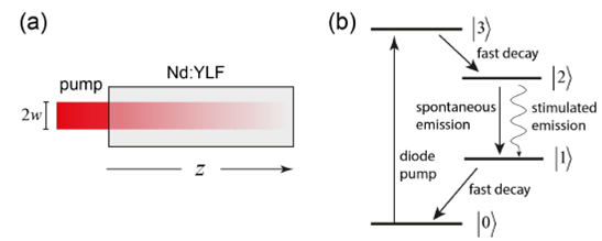
FIGURE 1 Pumping and transitions allowed in the model. a) Longitudinal pumping; b) four-level system.
The first term of the right-hand side of (1) represents the pumping of Nd ions to the level
Here
The time evolution of the number of photons in the cavity is given by
The first term of the right-hand side of (4) corresponds to the loss of photons due to the cavity, where the photon lifetime
where Ri and Rc are the reflectivities of the input mirror and the output coupler, respectively, and a are the passive losses of the gain medium. The second term is the spontaneous emission where B is a factor that takes into account that only a small fraction of these photons are emitted into the solid angle that corresponds to the cavity mode. The exact value of this parameter is not important (we set it to 10-4); it is only required to seed the light amplification process. The third term represents the gain of photons due to stimulated emission, and the fourth and fifth terms are the photon losses due to absorption by the saturable absorber. We assume that the saturable absorber can be modeled as a two-level system 13, where Nbase and Nex are the density of Cr ions in the base and excited states, and
Finally, we need an equation for the time evolution of the Cr ions in the saturable absorber. This is given by
where
from which we can deduce that
The instantaneous output power can be obtained from the number of photons in the cavity and is given by 12
The population inversion as a function of time when lasing is inhibited (below threshold) can be obtained by setting the number of photons
where
We numerically solve Eqs. (3), (4) and (6) using the parameters given in Table I. We assume that the system is pumped with a rectangular pulse with a duration long enough to produce only one pulse from the laser, but never longer than
TABLE I Material and cavity parameters used in the simulations
| Parameter | Value |
|---|---|
| 798 nm | |
| |
1047 nm |
|
|
520s |
| |
6:9 x 1025 m3 |
| |
5 x 10 -24 m2 |
|
|
1:8 x 10-23 m2 |
|
|
1.470 |
| d | 12 mm |
|
|
4:3 x 10 -22 m2 |
|
|
8:2 x 10 -23 m2 |
|
|
3.4 s |
| w | 500 m |
| L | 28 mm |
|
|
0.1 cm -1 |
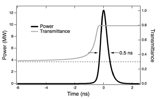
FIGURE 2 Pulse and Cr:YAG transmittance vs. time. Initial transmittance: 30%. Output coupler reflectivity: 50%.
Figure 3 shows the pulsewidth and energy per pulse vs. pump power for a fixed value of the output coupler reflectivity (50%) and for different values of the initial transmittance of the saturable absorber (30, 50, 70 and 90%). Again, the crystal is pumped with a 1.9 ms rectangular pulse. From these simulations we see that the minimum power required to obtain a pulse increases as the initial transmittance decreases. After this threshold is met, neither the pulsewidth nor the energy per pulse change significantly with pump power. This is to be expected. The saturable absorber requires a certain amount of fluence in order to be bleached, and this fluence increases with decreasing initial transmittance. Once the saturable absorber is bleached, most of the remaining energy stored as a population inversion in the gain medium is extracted by the pulse. Pumping above this threshold only reduces the time that the laser pulse occurs within the pump pulse, but does not increase its energy.
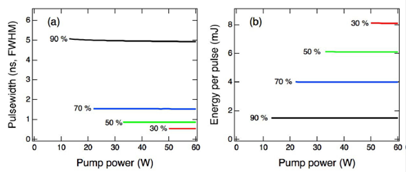
FIGURE 3 Numerical results: Dependence with pump power. a) Pulsewidth; b) energy per pulse. The percentages shown are the values of the initial transmittance of the saturable absorber. Output coupler reflectivity: 50%.
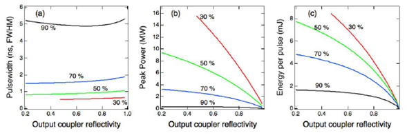
Figure 4 shows the results of the simulations when the output coupler reflectivity is varied, assuming
3.Experiment
The basic set-up used for our experiments is shown in Fig. 5. As a pump source we used a pulsed diode laser coupled to a 600 μm in diameter core, NA = 0.22 fiber. The output of the fiber was collimated by a 6 mm focal length lens and then focused onto a 12 mm long, a-cut Nd:YLF crystal. We used several Cr:YAG crystals as saturable absorbers with different initial transmittances. In order to avoid their fracture due to thermal stress, both the Nd:YLF and the Cr:YAG were covered with indium foil and placed inside a metal block to extract the heat produced by the pump. The temperature of the block was regulated by a Peltier cooler and kept at 18oC. The input mirror was flat, highly reflecting (>99%) at 1.047 μm and highly transmitting (>95%) at the pump wavelength, 798 nm. We used several output couplers with different reflectivities and different radii of curvature, ranging from flat to 500 mm. In order to reduce the pulsewidth, the cavity was made as short as possible, limited by the size of the components, 19 mm.
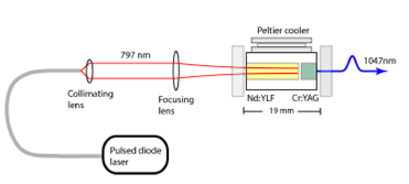
FIGURE 5 Experimental set-up. Fiber: 600 ¹m in diameter core, NA=0.22; collimating lens: 6 mm focal length. Several focusing lenses with different focal lengths were used.
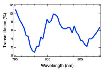
In order to maximize the fraction of the pump absorbed by the Nd:YLF crystal and at the same time minimize the pump power incident on the Cr:YAG, which would cause undesired partial bleaching and heating, we must pump with a wavelength that coincides with an absorption peak. Figure 6 shows the transmission of Nd:YLF as a function of wavelength for depolarized light. In the region shown in this figure, the highest absorption occurs at 798 nm. We adjusted the temperature of the diode to achieve this wavelength, obtaining emission centered at 798 with a FWHM bandwidth of 2.5 nm. According to the supplier of our crystal (Red Optronics), the Nd concentration is 1%, not the 0.5% used in our calculations. However, the fraction f of the pump that is absorbed by the gain medium, which ultimately is the parameter that matters, is approximately 0.985, which is the factor used in the numerical analysis. The discrepancy most likely is due to a few factors, such as the bandwidth of the pump, inaccuracies of the absorption cross-section of the medium and partial polarization of the pump beam.
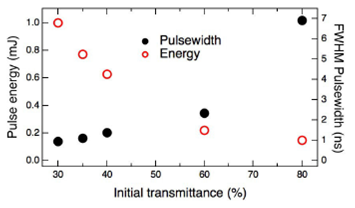
Several arrangements with different output couplers and Cr:YAG crystals were tested and measured. In all cases the trend agreed with the numerical predictions: the lower the initial transmittance of the Cr:YAG, the shorter the pulse, and the lower the reflectivity of the mirror, the more energetic the pulses as well as the more pump power required to obtain them. Examples of the measurements of the pulsewidth and energy per pulse for five different values of the initial trans- mittance of the saturable absorber are shown in Fig. 7. In all five cases the output coupler, cavity length, pump beam width, and repetition rate were the same; only the initial transmittance and the pump power required to obtain the pulses were changed for each data point.
Since our goal was to make a Q-switched laser with the shortest pulsewidth possible, we concentrated our efforts on the configuration where the shortest and most energetic pulses were obtained. This was accomplished with a Cr:YAG with a 30% initial transmittance and a flat output coupler with 55% reflectivity. The total optical path length taking into consideration the refractive indices of both crystals was 29 mm. The focal length of the focusing lens was 60 mm and the resulting width of the pump beam at the input surface of the Nd:YLF crystal was
where
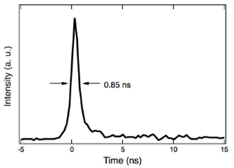
Figure 9 shows the energy per pulse vs. pulse number when the laser is pumped at a 40 Hz repetition rate. The system is very stable; the energy per pulse averaged over the 500 pulses shown in Fig. 9 is 2.32 mJ with a standard deviation of only 0.018 mJ. The peak power of these pulses is over 3 MW. Neither the energy per pulse nor the pulsewidth depend on the pump power, provided it is above the threshold required to obtain a pulse, which agrees with our simulations.
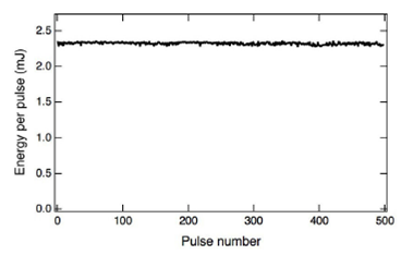
FIGURE 9 Pulse energy vs. pulse number. Repetition rate: 40 Hz. Pump power: 50 W. Pump pulsewidth: 1.9 ms.
We also estimated the bandwidth of the pulses and their spatial quality. To estimate the bandwidth we sent the pulses through a Michelson interferometer and observed the visibility of the interference pattern as a function of the path length difference. We found that the visibility of the fringes decreases significantly for path length differences above approximately 12 cm, corresponding to a time delay of ∼400 ps, around half the pulsewidth. From this we conclude that the spectrum of the pulse is close to the Fourier limit; in other words, it emits in a single-longitudinal or almost single-longitudinal mode. As for the spatial quality, in the vertical direction (along the crystal’s c axis) we obtained
Finally, as an example of its use in intended applications, we used this laser to obtain cascaded nonlinear processes in a single aperiodically poled lithium niobate crystal (APPLN). Using the procedure outlined in 15, the APPLN crystal was designed to simultaneously produce optical parametric generation (1.047 μm → 1.46 μm + 3.69 μm) and sum-frequency generation between the pump and the signal produced by the optical generation process (1.047 μm + 1.46 μm → 610 nm). The electrical poling technique as well as the procedure to make the mask required to create the poling electrodes are described in detail in 16. The dimensions of the APPLN crystal were 20 x 20 x 0.5 mm. Figure 10 shows the experimental set-up used to generate and detect the pulses at 610 nm produced with our laser and our APPLN crystal. The energy per pulse incident on the APPLN crystal was controlled by a half-waveplate and a Glan-Thompson polarizer. Since the APPLN crystal is only 500 𝜇m thick, it was necessary to use a pump with an elliptical cross-section to be able to send the entire beam through the crystal without exceeding the damage threshold fluence, which is around 2 J/cm2 for pulses that have a duration of the order of 1 ns. This was accomplished by sending the pulses through a combination of a spherical lens (f = 175 mm) and a cylindrical lens (f = 150 mm), with which we obtained an oval-shaped beam of approximately 0.25 x 1mm, FWHM, which has an area of
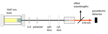
FIGURE 10 Experimental set-up for the generation and detection of short pulses of 610 nm through cascaded nonlinear interactions in APPLN.
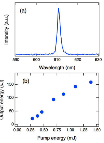
The results are shown in Fig. 11. Figure 11a) shows the measured spectrum; we obtained a pulse at 610.7 nm, very close to the 610 nm design wavelength. Figure 11b) shows the energy of the 610 nm pulses vs. the pump energy. We obtained a conversion of over 11%, which is high considering that the pulses were produced with two cascaded nonlinear interactions in a single-pass through the crystal. Enclosure of the APPLN crystal in a two-mirror cavity to obtain feedback (optical parametric oscillation) was not required due to the high peak intensity of the 750 ps pump pulses.
4.Conclusions and final remarks
We presented a diode-pumped, compact passively Q-switched laser that can emit pulses with pulsewidths lower than 1 nanosecond, more than 2.3 mJ per pulse and peak powers above 3 MW. The high energy and small pulsewidth are due in part to the use of Nd:YLF as the gain medium, since its upper state’s lifetime is large, which allows more energy to be stored in the crystal. By using Cr:YAG saturable absorbers with different initial transmittance values we could vary the pulsewidth from 6.8 ns to 750 ps.
We also presented a simple model that predicts fairly well the pulsewidth and the pump power required to obtain the pulses as a function of the cavity length, output coupler reflectivity and initial transmittance of the saturable absorber. The energy per pulse that we measured follows the trend predicted by the model: the lower the initial transmittance the higher the energy per pulse and the higher the pump power required; however, the measured energy is more than 3 times less than what is predicted. Most likely this is due to one of the assumptions in the model, namely, that the pump mode and cavity mode overlap perfectly in a cylinder of radius w, which is a simplification that may be far from valid. By carefully designing the cavity in order to match the pump and cavity modes, taking into account thermal lensing of gain medium, the energy per pulse could increase; however, this is beyond the scope of this work.
Finally, as an example of its intended applications we used this laser to produce cascaded nonlinear interactions in an aperiodically poled lithium niobate crystal, obtaining short pulses of more than 150 μJ at 610 nm.

