


![Efecto de la imidazolina [IM-NH17] en el proceso de corrosión del acero api5l-x52 en salmueras acidificadas](/img/es/prev.gif)


Servicios Personalizados
Revista
Articulo
 Inglés (pdf)
 Artículo en XML
 Referencias del artículo
 Enviar artículo por email
Indicadores
-
 Citado por SciELO
 -
 Accesos
Links relacionados
-
 Similares en
SciELO
Similares en
SciELO
Compartir

 Permalink
Ingeniería, investigación y tecnología
versión On-line ISSN 2594-0732versión impresa ISSN 1405-7743
Ing. invest. y tecnol. vol.10 no.4 Ciudad de México oct./dic. 2009
Nonlinear Motion Control of a Rotary Wing Vehicle Powered by Four Rotors
Control no lineal del movimiento de un vehículo de ala rotativa impulsado por cuatro rotores
S. Araujo–Estrada1, E. Liceaga–Castro2, and H. Rodríguez–Cortés3
1 Escuela Superior de Ingeniería Mecánica y Eléctrica, Unidad Ticomán, México. E–mail: leon_re4@hotmail.com
2 Escuela Superior de Ingeniería Mecánica y Eléctrica, Unidad Ticomán, México.. E–mail: eliceagac@uk2.net
3 Departamento de Ingeniería Eléctrica, CINVESTAV–IPN. México. E–mail: hrodriguez@cinvestav.mx
Recibido: octubre de 2007
Aceptado: marzo de 2008
Abstract
This paper presents a solution to the motion control problem for a rotary wing vehicle powered by four rotors. It is considered that the rotary wing vehicle performs an indoor low speed flight mission so that aerodynamic effects are not taken into account. The proposed controller is based on a combination of the well–known backstepping nonlinear control design technique and bounded controllers. It is shown that the resulting closed—loop dynamics evolves inside a set where singularities are avoided. Numerical simulations show the performance of the proposed controller.
Keywords: Nonlinear control, bounded control, unmanned aerial vehicle, rotary wing vehicle, trajectory tracking asymptotic stability.
Resumen
En este artículo se presenta una solución al problema de seguimiento de trayectorias en un vehículo de ala rotativa impulsado por cuatro rotores. Se considera que el vehículo de ala rotativa realiza una misión en un espacio cerrado con baja velocidad de manera que los efectos aerodinámicos no se toman en cuenta. Se muestra que la dinámica en lazo cerrado resultante evoluciona en un espacio en el cual no se tienen singularidades. Por medio de simulaciones numéricas se muestra el desempeño de la estrategia de control propuesta.
Desciptores: Control no lineal, control acotado, vehículo aéreo no tripulado, vehículo de ala rotativa, seguimiento de trayectorias, estabilidad asintótica.
Introduction
In the past years there has been a steady increase in the development of sophisticated unmanned aerial vehicles (UAVs) for military and civilian applications. The UAVs have a variety of potential uses, including local reconnaissance, fire control, and detection of intruders. Law enforcement organizations use for hostage rescue, border patrol, traffic surveillance and riot control (Davis et al., 1998). The commercial success of UAVs together with the revolutionary advances in the miniaturization of computers, sensors and mechanical actuators has posed new challenges to control engineers. Nowadays, UAVs are considered challenging benchmarks for the development of new nonlinear controllers to solve the motion control problem on existing UAV configurations and recently proposed UAV configurations (Kendoul et al., 2005).
Existing UAVs can be classified mainly in two classes: rotary wing vehicles and fixed wing vehicles. For missions requiring the vehicle to remain stationary (hover) or to maneuver in tightly constrained environments rotary wing vehicles have significant advantages over fixed wing vehicles. For example, a traffic surveillance mission around buildings requires a hovering vehicle with good maneuverable characteristics. However, it is important to point out that hover flight consumes approximately twice the power of a similarly loaded fixed wing vehicle moving forward. This energy consumption difference between fixed and rotary wing vehicles is expected to be solved by new power technologies. The hope is that new power technologies will allow achieving reasonable endurance for rotary wing vehicles.
In this paper a rotorcraft powered by four non–tilting rotors known as the X4–flyer (Hamel et al., 2002) or the Dragan–flyer is considered. It is assumed that the vehicle performs an indoor low speed flight mission so that aerodynamic effects are disregarded. Although disregarding aerodynamic effects is a quite restrictive assumption it is common in most of the existing literature about this rotorcraft.
Besides its practical relevance, the Dragan–flyer system is an interesting case of study, e.g. it is a six degrees of freedom mechanical system whose dynamics is described by an under–actuated twelfth order highly coupled nonlinear model.
The goal of this paper is to address and solve the trajectory tracking problem. In particular, the problem is solved by combining the backstepping technique introduce in (Sepulchre et al., 1997) and the results on bounded controllers of (Kaliora et al., 2001). It is important to point out that the trajectory tracking problem for this rotary wing vehicle has been addressed in (Salazar et al., 2005) using a nested saturation control algorithm and in (Hamel et al., 2002) using the backstepping technique. However, it is necessary to underscore that the proposed controller in this paper is different to the controller presented in (Hamel et al., 2002) as the translational dynamics has a different closed–loop behavior.
The rest of the paper is organized as follows. In Section II the rotorcraft dynamical model and a precise definition of the control problem of interest are defined. Section III is devoted to the design of the state feedback controller. In Section IV the effectiveness of the control design is shown through a series of numerical simulations. Finally, in Section V some concluding remarks are presented.
II. The model
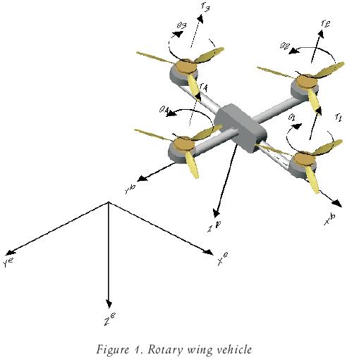
The rotary wing vehicle is shown in figure 1. It is powered by four non–tilting rotors attached to a rigid frame. The dynamical model of the rotary wing vehicle can be obtained as follows. Let Oxe ye ze denote a right–hand inertial frame (earth frame) such that ze points downwards into the earth and Oxb yb zb a right–hand frame fixed to the centre of mass of the aircraft structure (body frame). The vehicle dynamics in the body frame is described by (Roskam, 1982)

where m represents the vehicle mass,
V bCM=[u v w]T
denotes the linear velocity of the vehicle centre of mass expressed in the body axis frame, Ω =[p q r]T denote the angular velocity of the body frame, I is the vehicle inertia matrix1, Feb represents the external applied forces expressed in the body frame and Mebrepresents the external applied moments expressed in the body frame. In order to express the vehicle dynamics (1) referred to earth axis, it is necessary to specify the orientation of the body axis with respect to the earth frame. Considering the classical Euler yaw–pitch–roll rotation sequence. The rotation matrix that describes the orientation of the body reference frame relative to the earth frame is given by

where Η =[ θ ψ]T are the Euler angles with the roll angular displacement, θ the pitch angular displacement and Ψ the yaw angular displacement. Moreover, cx = cos(x) and sx = sin(x). On the other hand, the body frame angular velocity Ω is related to the Euler angles velocity as follows (Roskam, 1982)

From equation (2) we have that the relationship between the velocity components in the earth frame and the velocity components in the body frame is defined as

where VeCM = [x y z]T is the linear velocity of the vehicle centre of mass expressed in the earth frame. Thus, the vehicle dynamics expressed in the earth frame can be written as

where the following facts have been considered R–1 =RT,R.RTVbCM =–Sk(Ω)VbCM, with Sk(Ω) a skew symmetric matrix such that ΩxVbCM =Sk(Ω)V bCM and the new inertia matrix IΗ =WT I W has been introduced. Since we are not considering aerodynamic effects, the external applied forces expressed in the body frame are the vehicle weight and the total thrust produced by the four rotors, that is,

where TT = ∑4i=1 Ti with Ti the thrust of each rotor. It is shown in (Gressow et al., 1978) that the thrust generated by each rotor can be expressed as
Ti =CTi π r4i ρ ω2i
where CT is the thrust coefficient of rotor i, ρ is the air density, ri is the radius of rotor i and ωi is the angular velocity of rotor i. The external applied moments in the body frame are defined as follows. The pitching motion is actuated by the moment around yb produced by increasing the thrust of rotor 1 and reducing the thrust of rotor 3. The roll movement is generated in a similar way, that is, by producing a differential thrust between rotors 2 and 4. Due to the torque applied to the rotor shaft by the motors a reaction torque of the same magnitude but opposite direction is experienced on the structure of the vehicle. By manipulating these reaction torques it is possible to control the yaw moment. Finally, the external applied moment is given by

where  is the distance between the rotor rotation axis and the aircraft centre of mass and Qi is the reaction moment produced by rotor i. The reaction moment is given as (Gressow et al., 1978)
Q1 =CQi π r5i ρ ω2i
As shown in (Hamel et al., 2002) there exist a globally defined change of coordinates from
[–TT L M N]T to [ω21 ω22 ω23 ω24]T for CTi >0 and CQi >0.
The control objective is to asymptotically track prescribed trajectories for the vehicle spatial position (x, y, z) and the yaw orientation Ψ. In the following, we show that the considered control objective is achievable with a nonlinear time variant state feedback under the following standing assumption
– All system states are measurable and all system physical parameters are known.
Control design
In this section we present a bounded backstepping control design for the rotary wing vehicle modeled by equation (5). The control strategy is developed as follows. First, the controller for the vehicle vertical motion is designed and then through the pitch and roll angles the vehicle position in the plane xy is controlled. The motion in the yaw direction is controlled independently. From the first equation of (5) we have that the translational dynamics is described by

Vertical motion control can be obtained by defining the total thrust as

where γz is a function defined in such a way that the dynamic equation

globally asymptotically satisfies

The translational dynamics (8) in closed loop with the controller (9) is described by the following equations

Following the backstepping nonlinear control design methodology (Sepulchre, 1997) the motion control in the x and y directions can be achieved through θ and as follows.
Consider the functions

where γx and γy are functions that will be defined in a similar way to γz. Note that the new variables ζx and ζx will be well defined provided

therefore γz needs to satisfy the following condition

The condition above will be fulfilled by designing γz as a bounded function; this will be achieved following the bounded control design technique proposed in (Kaliora et al., 2001).
Solving equation (11) for tan (θ) and tan(), and replacing them into equation (10) we obtain

Supposing that ζx and ζx are vanishing perturbations the trajectory tracking problem in the plane x–y can be solved by selecting the functions γx and γy in such a way that the following dynamic equations

globally asymptotically satisfy

Now, we force the variables ζx and ζx to be vanishing perturbations. For, let us define the following linearizing feedback for the angular dynamics
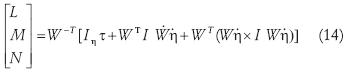
where τ = is the new control input. With the controller defined by (14) the rotational dynamics reads as follows

It is easy to verify that the system described by equations (10) and (15) eith output (11) has vector relative degree {r1, r2} ={2,2} provided (12) and

holds. As a result, we have

is the decoupling matrix. The main characteristics of the proposed controller can be stated as follows.
Proposition 1
Consider the rotary wing vehicle dynamics described by equations (5). Let xd (t), yd (t), Zd (t) and Ψd(t) be reference signals with bounded derivatives. The state feedback control law defined by (9), (11) (14) and

with

and

where λ(.2)1 and λ(.)2 are constants such that the polynomial s2 +λ(.)1 has all roots with negative real part, positive constants εx, εy and

generates a closed loop dynamics such that, for any initial conditions in the set

the trajectories of the closed loop system remain in S and are such that

for any positive constant σz>0.
Proof
To begin with, note that vertical motion dynamics expressed in terms of the vertical tracking error is described by

as shown in (Kaliora et al., 2001) the dynamics (23) is globally asymptotically stable (LES) so that z (t) converges to zd (t). Moreover, from (21) we have that

thus the new coordinates defined in (11) are well defined in the set S. In a similar way we have that the dynamics

are GAS and LES. As a consequence, there exists quadratic Lyapunov functions

with Wx and Wy positive definite functions along (24). Additionally, it is easy to verify that for the dynamic equations

there exist radially unbouned Lyapunov functions  and
and  such that

with Wζx and Wζy. being positive definite functions. Consequently, there exist constants кx and кy such that

Note now that the vehicle dynamics (5) in closed—loop with (9), (14) and (18) can be expressed in terms of the

so that the time derivative of the Lyapunov functions (25) along (28) gives

Consider now equation (27) and some positive constants Kj,k2 and Kg.Then theLyapunovfunction time derivatives (29) can be bounded as follows

which gives

this implies that along the trajectories of the closed loop dynamics Vx and Vy are bounded. As a result, the tracking errors ex and ey and their time derivatives are bounded and, by standard properties of cascade systems x(t) and y(t) converge to xd (t) and yd (t) respectively. It is easy to verify that the last equation of (28) is GAS and Ψ(t) converges to Ψd (t). Finally, straightforward computations show that

Note that the functions  , and –
 can be written in terms of {ζx, ζy, γx, γy, γz} then the diffeomorphism from
 is well defined in the set S. This completes the proof.
Remark
The control law of Proposition 1 has εx and εy as free parameters that could be used to enforce saturation limits on the actuators. Moreover, as the closed–loop dynamics evolves inside S the singularities in equations (9) and (14) are avoided.
Simulation results
Numerical simulations were carried out to asses the performance of the controller proposed. The numerical value of the vehicle parameters are presented in table 1.

Note that we consider similar characteristics for all rotors. The desired trajectory is defined as follows

In the numerical simulations we have considered the following initial conditions

In order to tune the controller parameters we do need to be careful to fulfill condition (12) this can be achieved by selecting adequately the controller gain εz. Note that through the controller gains εx, εy the functions γx and γy can be arbitrarily bounded. However, by bounding γx and γy we bound the available control force and slow the controller response. In the following numerical simulations we select the controller parameters presented in table 2.

In order to test the controller robustness in the following simulations the linearizing controller (14) is not included. Figures 2 and 3 show the time histories of the trajectory tracking as it can be observed they converge asymptotically to zero. The divergence observed at t =50 seg corresponds to the non smooth change of reference. However, after a transient period the trajectory tracking errors converge asymptotically to zero.
Figures 4 and 5 display time histories of the control signals, as it can be they remain bounded. Finally, in Figures 6 and 7 the time histories of the states  as well as (ζx, ζy) and its time derivatives are shown. Note that all these signals remain bounded showing that the diffeomorphism from is well defined.
Conclusions
The trajectory tracking problem for a rotary wing vehicle powered by four rotors has been addressed and solved by means of a full information control law, which is based on the backstepping technique and bounded controllers. Numerical simulations have been proposed to illustrate the properties of the closed loop system.
A few issues are left open in the present paper. First, all the system parameters are assumed to be known. Second, all the states are assumed to be measurable, hence further work is necessary to relax (or avoid) these assumptions. A straightforward solution to the issues left open in this paper is to include an observer/estimator to observe some system' states and to estimate some system's parameters, for instance translational velocities, angular displacements and vehicle mass. The main complications in this direction is to be able to conclude some kind of stability of the new resulting nonlinear closed—loop dynamics now composed of vehicle dynamics, controller and observer.
Acknowledgments
This work has been partially supported by the Instituto Politécnico Nacional under the project SIP–20060127. Authors would like to thank to anonymous reviewers for their helpful suggestions.
References
Davis Jr. W.R., Kosicki B.B., Boroson D.M., Kostishack D.F. Micro Air Vehicles for Optical Surveillance. The Lincoln Laboratory Journal, 9:2, 1998. [ Links ]
Gessow A., Myers C.G. Jr. Aerodinamics of the Helicopter. FREDERICK UNGAR PUBLISHING CO. New York. Fifth Printing. 1978. [ Links ]
Hamel T., Mahony R., Lozano R. Dynamic Modelling and Configuration Stabilization for an X4–flyer. Proc. of the 15th Triennial World IFAC Congress Barcelona, Spain, 2002. [ Links ]
Kaliora G., Astolfi A. A Simple Design for the Stabilization of Cascaded Nonlinear Systems with Bounded Control.Proc. of the 40th Conference on Decision and Control Orlando, FL, pp. 3784–3789, 2001. [ Links ]
Kendoul F., Fantoni I., Lozano R. Modelling and Control of Small Autonomous Aircraft Having Two Tilting Rotors. Proc. of the 44th Conference on Decision and Control and the European Control Conference 2005, Seville, Spain, December 12–15, 2005. [ Links ]
Roskam J. Airplane Flight Dynamics and Automatic Flight Controls. Part I, A. Roskam Aviation and Engineering Corporation. 1982. [ Links ]
Salazar–Cruz S., Palomino A., Lozano R. Trajectory Tracking for a Four Rotor Mini–craft. Proc. of the 44th Conference on Decision and Control and the European Control Conference 2005, Seville, Spain, December 12–15, 2005. [ Links ]
Sepulchre R., Jankovic M., Kokotovic P. Constructive Nonlinear Control. London. Springer Verlag. 1997. [ Links ]
About the authors
Sergio Araujo–Estrada. Is a M.S. student at the Centro de Investigación y de Estudios Avanzados. He received his bachelor in aeronautical engineering from the Instituto Politécnico Nacional in 2008. His research interests are design and control of unmanned aerial vehicles.
Eduardo Liceaga–Castro. He received his bachelor in aeronautical engineering from the Instituto Politécnico Nacional, M.S. in automatic control from the Centro de Investigación y de Estudios Avanzados and Ph. D. from Glasgow University. He was a postdoctoral research fellow at Glasgow University, Strathclyde University and Glasgow Caledonian University. He has held academic appointments at Universidad Carlos III, Escuela Superior de Ingeniería Mecánica y Eléctrica Unidad Ticomán and Instituto de Estudios Superiores de Monterrey Campus Cd. de México. He has worked at Daimler Chrysler in Germany. His current research interests include nonlinear control of electric machines and aerial vehicles.
Hugo Rodríguez–Cortés. Is a mechatronics researcher at the Centro de Investigación y de Estudios Avanzados. He received his bachelor in aeronautical engineering from the Instituto Politécnico Nacional in 1995, M.S. in automatic control from the Centro de Investigación y de Estudios Avanzados in 1997 and doctorate in signal processing and automatic control from Paris XI University in 2002. He has been a postdoctoral research fellow at the Imperial College of Technology and Medicine and Northeastern University. His research interests are design and control of unmanned aerial vehicles.
1 As the vehicle has two symmetry axes I = diag{Ixx, Iyy, Izz}.

