


 text new page (beta)
 English (pdf)
 Article in xml format
 Article references
 Send this article by e-mail
 Cited by SciELO
  Similars in
SciELO
Similars in
SciELO 
 Permalink
1. Introduction
Liquid phase processing, or melt-cast, is an economical method to produce intricate shapes at the industrial scale. For metal matrix-carbon nanotube (MM-CNTs) nanocomposite fabrication, there are two major limitations: high melting temperature of matrix metal which may damage CNTs, and segregation of CNTs due to the surface tension forces of molten metal. In this regard, aluminum is a promising matrix material having low melting point and ease of subsequent processing; however, high surface tension forces of molten aluminum (i.e., 860 mN/m) remained a problem for the uniform dispersion of CNTs (Dujardin, Ebbesen, Hiura, & Tanigaki, 1994). To overcome segregation of CNTs in aluminum melt, some additional steps or processes (e.g., coating of CNTs and stirring) would be required. Liquid phase processes, nevertheless, suffer poor incorporation and distribution of the particles/reinforcements in the matrix. These problems become especially significant because of the extremely small size of CNTs, which causes acute agglomeration tendency and reduced wettability with the melt. To improve the dispersion and wettability of CNTs in molten aluminum, researchers have coated CNTs with different types of materials, e.g., Ni (Cho, Lim, Choe, & Lee, 2010), Cu (Chen, Wu, Lin, & Tan, 1999), Al (So et al., 2011), and SiC (So et al., 2013). The coated CNTs are then used as precursors for the incorporation in molten aluminum. In a similar work, Ko et al. (2013) first produced the powder precursor by mechanical milling of Al powder and CNTs. Then, nickel was electroplated on the milled powder, which increased its wetting with molten aluminum during the subsequent process. They have investigated 10 and 20 wt.% of multi wall carbon nanotubes (MWCNTs). The resultant cast aluminum-carbon nanotube (CNT/Al) nanocomposite exhibited good wetting of CNTs with matrix, although some segregation was also observed.
A further improvement in the dispersion of CNTs in the molten matrix occurred by the emergence of the mechanical stirring of the melt (Abbasipour, Niroumand, & Vaghefi, 2010; Li, Viereckl, Rottmair, & Singer, 2009; Zeng et al., 2010). Recently, Rashad, Awadallah, and Wifi (2013) used a novel approach, in which they first ball-milled aluminum powder and CNTs. Then, green billets of the milled powder were prepared and incorporated in molten aluminum during mechanical stirring. A good dispersion and interfacial bonding was achieved which resulted in increased mechanical strength (∼35%).
Abbasipour et al. (2010) fabricated CNT/Al nanocomposite of A356 cast aluminum alloy using compocasting technique, which is basically a stir casting method but it allows casting the composite in semi-molten state. They reduced the segregation of CNTs by first coating CNTs by electroless nickel plating and then injected the coated CNTs by the injector. Subsequently, it was cast in semi-liquidus forms. They reported increased hardness along with good nanotube dispersion in the matrix.
Similarly, Hamed et al. (Elshalakany, Osman, Khattab, Azzam, & Zaki, 2014) reported on the fabrication of CNT/Al nanocomposite by a combination of rheocasting and squeeze casting. They used a hypoeutectic aluminum-silicon alloy as matrix material. Their method caused de-bundling and dispersion of CNTs; additionally, they observed refinement of grain size and increased mechanical properties.
The above-mentioned methods used different types of mechanical forces to disperse the nanotubes in the matrix, which though helped the dispersion but also induced certain level of degradation or defects in the nanotubes, which made them less contributing to the strengthening of the matrix. We are reporting on the fabrication of CNT/Al nanocomposite using induction melting. In the present work, the innate stirring action of induction melting was used to disperse CNTs in molten aluminum, hence reducing the degradation of the nanotubes during the dispersion process. Previously, Wilson, Barrera, and Bayazitoglu (2010) used the induction technique to melt the pre-mixed and mechanically-dispersed powders of CNTs and titanium. They have benefited rapid heating rate of induction technique to avoid thermal degradation of the nanotubes; otherwise, slow heating for the melting of titanium (melting point of titanium is 1677 °C) would cause thermal damage to the nanotubes. However, the technique has not been so far reported to disperse the nanotubes in the metal matrix during the fabrication of MM-CNT nanocomposites, to the best of our information.
1.1 Hypothesis and approach
In the previous discussion it has been mentioned that many researchers have tried various melt-cast routes to fabricate CNT/Al nanocomposites; nonetheless, their efforts have been mainly limited to mechanical stirring. In the present study, we have worked on the hypothesis of using induction melting to utilize the associated electromagnetic stirring action for the dispersion of nanotubes in molten aluminum. The rapid heating rate of induction heating will also help to avoid degradation of the nanotubes, which in turn increases the contribution of the nanotubes toward strengthening of the composite.
A major hindrance in using induction melting for aluminum is its reduced thermal efficiency due to high electrical and thermal conductivity of aluminum. In usual practice, graphite susceptors are used to increase thermal efficiency of the process; however, it limits the stirring action of the induction melting. Therefore, we designed a specific induction coil which, can render enough thermal efficiency along with stirring to melt aluminum and disperse CNTs.
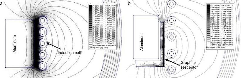
For the previously mentioned purpose, a coil was designed on the bases of the geometrical analysis, the thermal analysis and the electromagnetic analysis (Kennedy, 2013; Vaughan & Williamson, 1945). The results of these analyses for the present work are given in Table 1. Using these design parameters, the heating efficiency of the coil and stirring force in the melt were calculated according to the simulation work of Julio et al. (Walter & Ceglia, 2011) using finite element method magnetic software (FEMM 4.2). The coil design considerations, relevant simulation and efficiency factors are discussed in detail elsewhere (Mansoor & Shahid, 2014). Figure 1 represents the distribution of the magnetic fields in two types of induction melting approaches. In Figure 1 a, magnetic field lines are plotted without any susceptor material, while in Figure 1 b, a graphite susceptor is placed between the coil and the crucible. It could be seen that the presence of the susceptor has limited the magnetic field lines. The calculations showed that a heating efficiency >60% and stirring force <3 mN was achievable at the used parameters of the induction generator (i.e., frequency of 10 kHz and current of 100 A). Therefore, the designed coil was used for the subsequent experimental work.
Table 1 Results of the coil design analyses.
| Geometrical analysis | |
| Height of molten metal | 5.5 cm |
| Diameter of molten metal | 3.0 cm |
| Volume of the molten melt | 38.9 cm3 |
| Internal diameter of the induction coil | 45.0 cm |
| Height of the inductor coil | 6.0 cm |
| Thermal analysis | |
| Energy to melt aluminum | 69,850 J |
| Energy to superheat molten aluminum | 32,042 J |
| Energy to melt slag | 144 J |
| Total heat energy required | 102,036 J |
| Electromagnetic analysis | |
| Maximum magnetic flux density | 0.00409 T |
| Current density through the coil | 5.67 A mm−2 |
| Number of turns of the coil | 4.47 turns |
2. Experimental
The multiwalled carbon nanotubes (MWCNTs) used for the present work were synthesized using chemical vapor deposition. The detailed synthesis of MWCNTs is discussed elsewhere (Mansoor & Shahid, 2014). The nanotubes had 10 nm outer diameter and 1.5 μm ca. length. High purity aluminum (AA1199) was used for the matrix material in wire (diameter: 4 mm) form. The aluminum wires were cut into 1 in. staples and treated with 10% solution of sodium hydroxide and washed to remove any kind of oil and excessive oxide layer on the surface. Subsequently, the washed aluminum was preheated for 30 min at 150 °C to eliminate any moisture entrapped on the surface.
The flux used for the melting purpose was a mixture of "recycling and remelting flux" and "cleaning flux" supplied by FOSECO under the trade names of COVERAL-912 and ALUFLUX-3, respectively. The purpose of using multi-flux was to reduce the melting temperature of aluminum and to increase the reactivity of aluminum with CNTs. A mixture of the flux and pre-weighed MWCNTs was prepared using a mortar and a pestle. For each batch having 20 g of aluminum: 2 g of flux [50 wt.% COVERAL + 50 wt.% ALUFLUX] and CNTs [0, 0.1 and 0.2 vol.%] were used. Fabrication of the composite was carried out in an air induction furnace using the previously described coil design.
The excess amount of fluxes was purposely used for the fabrication of the composite because the melting was carried out in an air induction furnace and CNTs had tendency to oxidize before the melting temperature of aluminum (Jeong et al., 2004; Mansoor & Shahid, 2015). Excess amount of the fluxes would provide a cover of low density molten salts at top of the melt, preventing the oxidation of the nanotubes and aluminum besides other benefits such as early melting, removal of dross and impurities sink. However, high flux contents may cause retention of elements (like potassium, sodium, calcium, etc.) in the melt. To avoid the retention of the impurities in the melt, a "cleaning flux" (ALUFLUX-3) was added into the "recycling and remelting flux" (COVERAL-912). The cleaning flux has a strong tendency to remove oxides, dross and inclusions (FOSECO, 2012). Moreover, the operational temperature was kept below 790 °C because beyond this temperature the tendency of molten aluminum to pickup hydrogen from the atmosphere and retain impurities from flux increases remarkably (Majidi, Shabestari, & Aboutalebi, 2007; Shih & Wen, 2005).
The procedure used in the present work to fabricate CNT/Al composite is a follows: an alumina crucible (diameter: 30 mm) was placed in the induction coil and aluminum staples were positioned vertically in it (step-I). The mixture of the fluxes and the nanotubes was poured in the crucible when aluminum became semi-molten at around 660 °C (step-II). Addition of the flux caused the removal of the surface oxide and rapid melting of aluminum. Meanwhile, the flux became molten and covered the top surface of the melt preventing it from oxidation. In step-III, the nanotube present in the flux moved toward the interface of molten flux and aluminum under gravity. At this stage, the temperature of the melt was 760 °C. Generic stirring action of induction heating picked the nanotubes from the interface of flux-aluminum and dispersed them into the melt. Low density of the molten fluxes prevented their sinkage/dispersion in molten aluminum. Step-VI was basically the dispersion stage, where the melt was held for 10 min while keeping the temperature around 760 °C. No manual or mechanical stirring was carried out. Various steps involved in the fabrication of the composite are schematically shown in Figure 2. After the hold time, the molten flux was skimmed using a stainless steel spatula and the melt was poured into a rectangular copper mold (65 mm × 20 mm × 10 mm), which was preheated to 150 °C. The solidified ingots were homogenized at 540 °C for 1 h in argon atmosphere; subsequently, the ingots were cold rolled to attain a final thickness of 0.5 mm using two-high roll mills. Here, it is worth mentioning that all the castings (pure aluminum, Al-0.1% MWCNT and Al-0.2% MWCNT) were carried out under the same processing conditions, i.e., quantity of flux used, processing temperature, holding time and solidification, to establish the effect of the addition of CNTs.
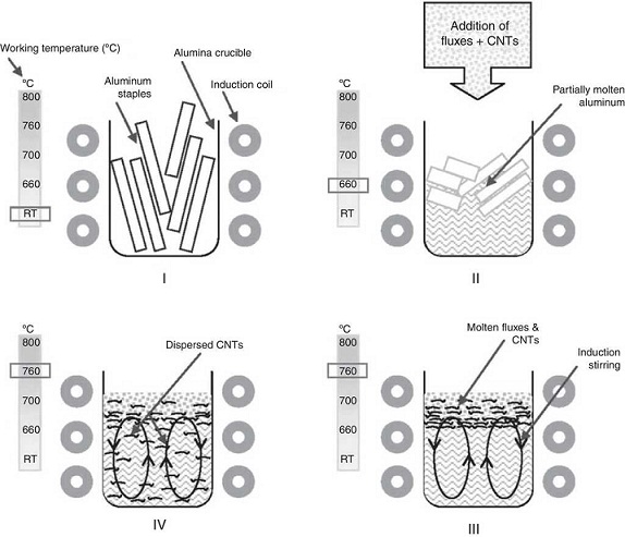
Figure 2 Schematic of the various stages during fabrication of Al-CNT nanocomposite using air induction furnace.
For the present work, a specimen of MWCNT was prepared for transmission electron microscopy (TEM) by first sonicating the nanotubes in ethanol and then dropping the suspension on a carbon coated grid, which was dried in a vacuum desiccator prior to its use. For the TEM studies of the composite, 3 mm discs were punched from the rolled strips and thinned to <300 μm. The discs were perforated using the twin-jet method with 10% perchloric acid solution. TEM studies were carried out in bright field illumination mode at 120 kV working potential difference.
The structure of a cast specimen of the nanocomposite was studied using scanning electron microscope (SEM) in secondary electron mode with working distance of 10 mm at 20 kV. Deep etching of the composite specimens was performed using 10% solution of sodium hydroxide.
To find the crystallite size and lattice strain, various rolled samples were studied using a Siemens D-500 X-ray diffractometer. A cobalt X-ray source with CoKα radiation having wavelength of 1.78897 Å was used. The diffractometer was operated at 40 kV and 40 mA tube potential and current, respectively, with a scan rate of 0.1° per minute and a step size of 0.02°-2θ . To calculate the crystallite size and lattice strain, the instrumental broadening was eliminated from the full width half maximum (FWHM) of the specimens under investigation. Therefore, a full annealed aluminum specimen was used to find the instrumental broadening. In the present study, the first three peaks of the aluminum spectrum (i.e. 111, 200 and 220) were used for profile analyses, while higher order peaks were not used because of the appearance of alpha 1 and 2 doublets. These alpha doublet peaks cause confusions in finding the corresponding FWHM values.
The crystallite size and lattice strain were calculated using the slope-intercept method, considering the combined effect of peak broadening by small crystallites and lattice strain (Suryanarayana & Norton, 1998). According to this method, the broadening of the diffraction peaks (B r ) is the sum of the individual broadening because of the small crystallite size (B c ) and lattice strain (B s ):
 (1)
(1)
Where,
 (2)
(2)
and
 (3)
(3)
 (4)
(4)
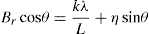
where, and where B o is the FWHM value of the peak under investigation, B i is the FWHM value of the instrumental broadening, k is a constant, λ is the wavelength of the radiation used, θ is the diffraction angle, L is the crystallite size and η is the lattice strain. Substituting Eqs. (3) and (4) in (1) and simplifying:
 (5)
(5)
In Eq. (5), kλ /L and η represent the intercept and slope of the straight line, which were used to calculate the crystallite size and the lattice strain, respectively.
Hardness testing was carried out on cold rolled strip specimens using a Vickers hardness testing machine at a load of 1 kg. Tensile specimens were prepared using a wire-cut electric discharge machine in accordance with the ASTM standard E8/E8M-11. An INSTRON universal testing machine with 0.02 s−1 strain rate and 25 mm gauge length was used to determine the tensile properties. A set of five specimens was used for each material (i.e., pure aluminum, 0.1% MWCNT-Al and 0.2% MWCNT-Al) to evaluate the mechanical properties. SEM and energy dispersion spectroscopy (EDS) were used to conduct fractographic studies and area analyses of the fracture surfaces of the broken tensile specimens, respectively.
3. Results and discussion
The nanotubes synthesized and used for the present work were of multi-walled type. A TEM micrograph of the nanotubes is shown in Figure 3 a, which shows that the length of the nanotubes is >1 μm. The diameters of the nanotubes were measured using the Olysia-TM software and a histogram (Figure 3 b) was plotted against the frequency function (260 measurements) to find the spread of the diameter of the nanotubes. The average diameter of the nanotubes was 10 ± 2 nm.
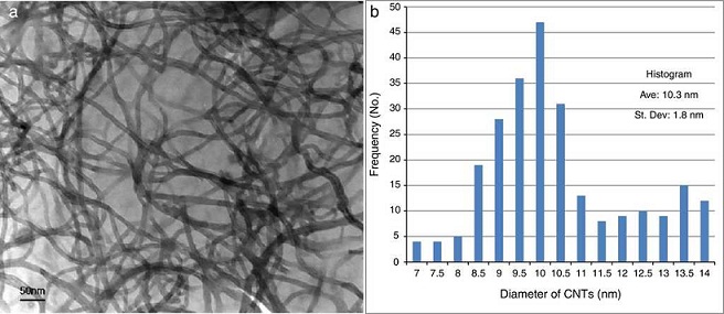
Figure 3 TEM of the nanotubes supported on a carbon coated grid, (a) TEM micrograph showing uniform MWCNTs and (b) histogram of the diameter and frequency function.
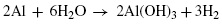
The SEM micrographs of the composite specimens are shown in Figure 4. The cast structure was accompanied by porosity (Figure 4 a). However, at higher magnification, the porosity appeared to be the removal of some phase, most likely MWCNTs, due to aggressive etching (Figure 4 b). Aluminum is a passive metal in water, forming a protective hydroxide layer on its surface; however, the presence of sodium hydroxide forms dissolvable aluminates of aluminum (Aleksandrov, Tsyganova, & Pisarev, 2003), according to reactions (6) and (7):
 (6)
(6)
 (7)
(7)
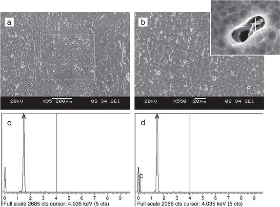
Figure 4 SEM studies of the cast 0.2vol.% MWCNTs nanocomposite in etched condition, (a and b) SEM micrograph showing the distribution of the nanotubes in aluminum matrix. Inset is at higher magnification (15k×) and (c and d) are the EDS spectrums of marked regions in (a) and inset of (b), respectively.
Deep etching was required to reveal the dispersion of the nanotubes in the matrix; therefore, a strong alkaline (sodium hydroxide) etchant was used, which preferentially attacked the interface between aluminum and the nanotubes (inset of Figure 4 b). It was observed that the MWCNTs were dispersed in the matrix along the grain boundaries. No clustering or segregation of the nanotubes was seen. Figure 4c and d are the EDS spectrums of marked regions of Figure 4 a and b, respectively. The area analysis at low magnification did not show the presence of the nanotubes because of their low concentration; nevertheless, at higher magnification and point analysis, a carbon peak appeared, confirming the presence of the nanotubes along the grain boundaries.
As mentioned earlier, specimens for TEM studies were prepared from rolled strips of pure aluminum and the composite; therefore, highly stressed microstructures were seen. In Figure 5 a, the microstructure of pure aluminum is shown, which contains lots of dislocation bands. It was also observed that a uniform thinning of the foil specimen occurred, which produced a larger area of the specimen for electron transmission. In the case of the composite, heterogeneous thinning occurred and fewer areas of the specimens were available for electron transmission. The nanotubes were seen embedded in the matrix; however, no evidences of the clustering of the nanotubes were found (Figure 5 b).
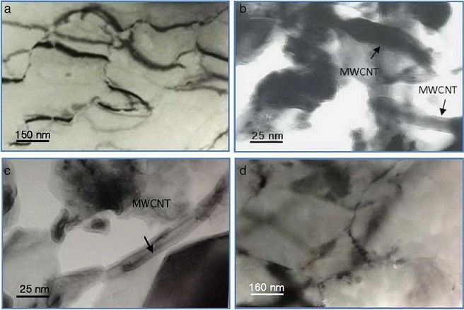
Figure 5 TEM of the nanocomposite specimens, (a) micrograph of pure aluminum and (b-d) micrographs of 0.2vol.% MWCNTs composite. The micrograph (d) is showing fine grain size of the composite.
Figure 6 displays superimposed XRD scans of aluminum specimens with various concentrations of MWCNTs. The diffraction angles of the peaks were used to identify the structure and Millers indices and found in accordance with PCPDF No: 851327. The XRD scans showed no evidence of a substantial amount of impurities such as potassium, sodium and calcium, among others, which could be retained in processing conditions having large amounts of fluxes. Nevertheless, on the bases of the XRD scan, it is hard to say that the impurities did not retain in the melt; however, if retained, their quantity is below the detection level of XRD, i.e., 2% (Barbara & Christine, n.d.).
The XRD peaks represented aluminum exclusively because the added constituent (the CNTs) was quite low in concentration to be detected by XRD. However, the effect of various concentrations of the CNTs in the composites reflected variations in FWHMs and peak intensities of the matrix (aluminum). This observation indicated some changes in the crystallite size and the lattice strain associated with the presences of the nanotubes. To find the variations in crystallite size and lattice strain, graphs were plotted between sinθ and B r cosθ ; where θ is the diffraction angle and B r is the FWMH values, as shown in Figure 7. The results obtained from the calculations are given in Table 2.
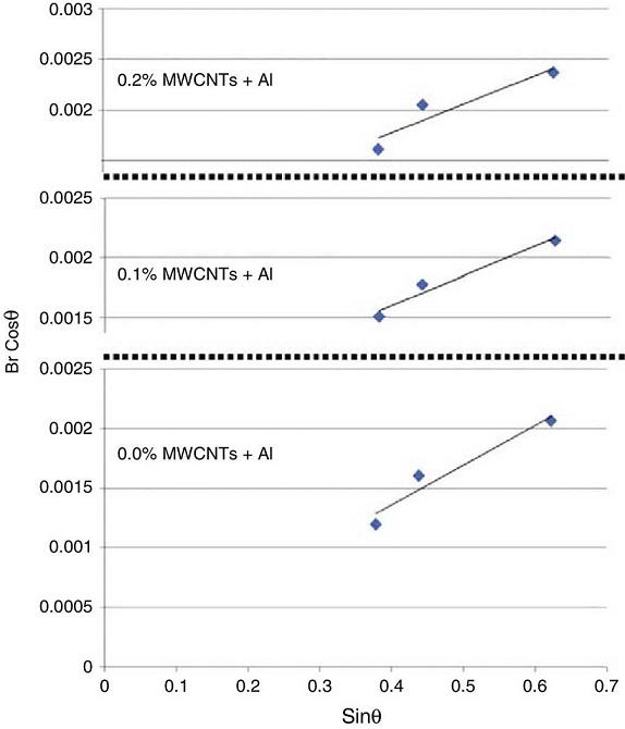
Figure 7 Plots of various specimens between sinθ and Br cosθ to find crystallite size and lattice strain.
Table 2 Results of the analyses of XRD scans for various specimens.
| Specimen ID | 0.0% MWCNTs-Al | 0.1% MWCNTs-Al | 0.2% MWCNTs-Al |
|---|---|---|---|
| Crystallite size (nm) | - | 360 ± 22 | 320 ± 24 |
| Lattice strain (×10−3) | 1.62 ± 0.21 | 2.5 ± 0.17 | 3.24 ± 0.21 |
Under the same processing conditions, pure aluminum did not show the crystallite size refinement detectable by XRD. However, the specimens having CNTs showed substantial refinement in their crystallite size. Typically, 360 nm and 320 nm crystallite size were observed in 0.1% and 0.2% MWCNTS-Al specimens, respectively. This systematic decrease in crystallite size could be attributed to the addition of CNTs. Additionally, an increase in the lattice strain was also observed with increasing contents of the nanotubes. Change in the lattice strain could be a feature of the mismatched coefficients of thermal expansion (CTE) of the two constituent materials i.e., CTEAl ∼ 23.6 K−1 and CTEMWCNTs ∼ 1 K−1 (Arsenault & Shi, 1986). Because of the increase in the lattice strains, an increase in dislocation density occurs, which may contribute to the strengthening of the composite (George, Kashyap, Rahul, & Yamdagni, 2005).
Stress-strain curves of the tested specimens are shown in Figure 8 c. In the results for pure aluminum specimens, deviations of the mechanical properties from standard pure aluminum AA1199-H18 were observed. These lower mechanical properties could be attributed to the processing conditions (i.e., usage of excessive flux), which might have resulted in entrapment of tiny flux particles and/or impurities. However, the same processing conditions were used for the preparation of CNT/Al composites. Therefore, a justified comparison could be possible for the strengthening effect of the nanotubes in the aluminum matrix. A net increase in yield strength, tensile strength, elongation and hardness, for the composites having various concentrations of CNTs, was ∼77%, ∼52%, ∼44% and ∼45%, respectively. The improvement in the mechanical properties seemed to be a synergistic effect of refinement in the crystallite size, increased lattice strain and solitary strengthening of the nanotubes. The results of mechanical testing are shown in Table 3.
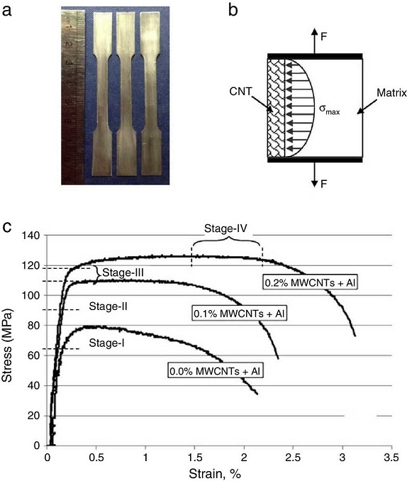
Figure 8 (a) Tensile specimens used for the testing, (b) stress distribution at the interface of CNT-Al under axial loading, and (c) experimental stress-strain curves of various specimens.
Table 3 Results of mechanical testing.
| MWCNTs (vol.%) | Elastic modulus (GPa) | Yield strength (MPa) | Tensile strength (MPa) | Elongation (%) | Hardness (HV) |
|---|---|---|---|---|---|
| 0 | 64 ± 1.5 | 65 ± 5 | 82 ± 4 | 2.15 ± 0.35 | 27 ± 4 |
| 0.1 | 65 ± 2.1 | 105 ± 4 | 112 ± 3 | 2.35 ± 0.40 | 34 ± 4 |
| 0.2 | 67 ± 2.9 | 115 ± 5 | 125 ± 3 | 3.10 ± 0.55 | 39 ± 5 |
| Net change (%) | ∼5 | ∼77 | ∼52 | ∼44 | ∼45 |
For the MM-CNT composites, it is believed that strengthening is influenced by the nanotubes, both in elastic and plastic deformation regimes. For simplicity, we consider a single CNT embedded in the aluminum matrix in the axial direction of loading, as shown in Figure 8 b. The applied tensile force develops a gradient of stress along the interface of the matrix (aluminum) and the reinforcement material (CNT) due to the difference in their mechanical properties e.g., Young's modulus, yield strength and plasticity. The maximum value of the tensile stress depends upon the length of the reinforcement material (CNT). In loading conditions, the matrix transfers the load to the CNTs; however, this transfer of load distribution is complex because of the following factors: the geometry of the nanotubes, orientation of the nanotubes and difference between elastic moduli of the matrix and the CNTs. In Figure 8 c, the tensile curves of pure aluminum and CNT/Al composites are shown, where the curves of the composites exhibit four deformation stages. In stage I, both the aluminum and CNTs undergo elastic deformation, as the stress limit is below the yield strength of aluminum (i.e., <65 MPa). Nevertheless, when the stress limit exceeds the yield strength of aluminum, the matrix undergoes plastic deformation while CNTs are still elastic. It is stage II and starts anywhere beyond 65 MPa applied stress level. In this stage, the composite behaves in a quasi-elastic way; therefore, the removal of applied tensile stress will effectuate elastic retention of the CNTs and compression deformation of the matrix. At stage III, both the matrix and CNTs deform plastically and/or delimitation/fracture of the interphase between matrix and CNT occurs. The stage represents the regions right after the yield points of the stress-strain diagrams in Figure 4 b. Finally (stage-IV), crack initiation a growth occurs within the composite, which continues until the fracture (Dieter, 1988).
The concurrent raise in strength and ductility is considered to be the transition in slip mode developed by the interaction between the nanotubes and the matrix. Dispersed nanotubes in the matrix act as fine precipitates; therefore, the mechanism of plastic deformation transits to bypass of dislocation reinforcement from shear dislocation reinforcement. The movement of bypassing dislocations is obstructed and collapsed at the interfaces by the CNTs (due to their ultra high strength). Such type of cross-slip phenomenon could be responsible for the simultaneous increase in strength and ductility of the nanocomposites (Dieter, 1988). Rashad et al. (2013) and Paramsothy, Gupta, Chan, and Kwok (2011) have reported similar type of behaviors in Mg and Al alloys reinforced by CNT. Goh, Wei, Lee, and Gupta (2006) also observed a similar type of behavior in CNT/Mg composites, where they related the increase in ductility of the composite with the activation of additional slip planes due to the presence of CNTs. As discussed earlier, in the present case, where we added CNTs to aluminum, a transition in slip mode was anticipated. Moreover, XRD scans (Figure 6) showed that the density of other planes (i.e., 200 and 311) was increased with the addition of the nanotubes. Cross-slip, in these planes, might have been activated because of the presence of the nanotubes, which was responsible for the observed increment in ductility. To confirm the assumption, texture analyses may be required in future work.
The fracture surfaces of the broken tensile specimens (both pure aluminum and the composite) were subjected to fractography using SEM. Fracture surfaces of pure aluminum specimens revealed a laminar type of fracture (Figure 9a). At locations where the fracture lines were deflected, fracture ridges were observed (Figure 9 b). The fracture surfaces of the composites revealed fine dimples (<10 μm) having pulled-out and embedded nanotubes on the lips and body, respectively (Figure 9c and d). In Figure 9 e, an EDS spectrum of the protruded nanotubes confirms the presence of CNTs in the matrix. The fracture dimples of the composite specimens were hollow and their centers were free from any kind of second phase (e.g. MWCNTs), which suggests that the facture was initiated within the matrix and not from the nanotubes. As the fracture propagated under testing conditions, the nanotubes, which were aligned (because of cold rolling) in the fracture direction, were pulled out by the sliding of the outer shells, contributing to resistance to the fracture growth. Such type of pulling and sliding of the outer shell in MM-CNTs has also been observed by other researchers (Miranda et al., 2013; Qingwen, Hao, Jin, & Zhongfan, 2002).
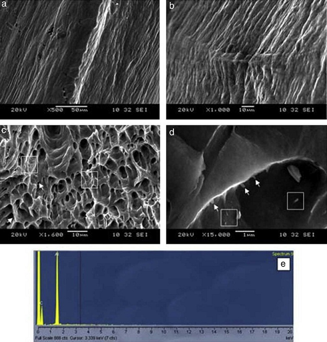
Figure 9 Fractography of the fracture surfaces of the broken tensile specimens, (a and b) fracture surface of pure aluminum and (c and d) fracture surface of the nanocomposite having 0.2vol.% MWCNTs. Arrows and squares are indicating pulled-out and embedded CNTs in the matrix, respectively. (e) EDS spectrum of the protruded nanotubes in (d) confirming the presence of CNTs.
4. Conclusion
The composites of CNT/Al were successfully fabricated using induction melting. SEM and TEM studies elaborated the homogeneous distribution of the nanotubes and no evidence of their segregation was found, which was further supported by a simultaneous increase in strengths, hardness and ductility. Simultaneous increase in strength and ductility could be attributed to the activation of more slip systems due to the presence of CNTs. In our opinion, induction melting holds strong promises for the fabrication of CNT/Al composites, especially because of its scale up capabilities.

