


 text new page (beta)
 English (pdf)
 Article in xml format
 Article references
 Send this article by e-mail
 Cited by SciELO
  Similars in
SciELO
Similars in
SciELO 
 Permalink
1 Introduction
Wireless power transfer (WPT) is a concept emerged from the ideas of Nikola Tesla at the end of the 19th century, but it is until the beginning of the 21st century when its boom increase exponentially due to trademarks such as WiTricity developed by MIT researchers [1,2], this technology is based on improved magnetic induction by resonance and electromagnetic coupling techniques. Recent work shows that resonant coupling can power transfer a receiver efficiently with little loss. [3,4]. Nowadays advances in power electronics and magnetic materials have made it possible to develop wireless transmitters and receivers from many gadgets to medical devices [5]. So currently WPT is a system that is drawing attention of engineers and researchers to use it and deliver the necessary electrical energy for different applications, this system is becoming common in new devices like laptops, smartphones, tablets and other electronic gadgets. Since popularity of this system is growing, it is possible to assume that more devices or electrical machinery of greater power demand will be powered wirelessly, therefore it is important to be prepared with tools and design methods for this robust wireless power transfer system, hence the suggestion of this work.
The idea is to transfer higher levels (kilowatts order) of wireless power with the highest energy efficiency and quality, for that it is necessary to identify the most relevant parameters that impact on the energy transfer, so this preliminary work focuses on analyzing and quantifying the impact of the separation between the transmitter coil and receiver, materials, geometries of the coils in order to ensure a larger coupling and therefore the possibility of transferring robust wireless power.
Other parameter considered is the number of turns, higher turns ratio also will ensure higher voltage at receiver and so higher power transfer, for WPT system with few turns resonating at a frequency in megahertz presents many difficulties in computational part and the practice (68), nevertheless, this works avoid this problem by using electromagnetic software with finite element method, it allows to simulate transmitter and receiver coils varying turns number and determine their impact on energy transfer.
2 WPT System Overview
The basic principle of WPT system involves the energy transmission from a transmitter coil (Tx) to a receiver coil (Rx) via an oscillating magnetic field, for that Tx coil is powered by alternating current (AC) flowing through Tx coil, it induces the magnetic field which can extends to the Rx coil and generates induced voltage through it, Figure 1a.
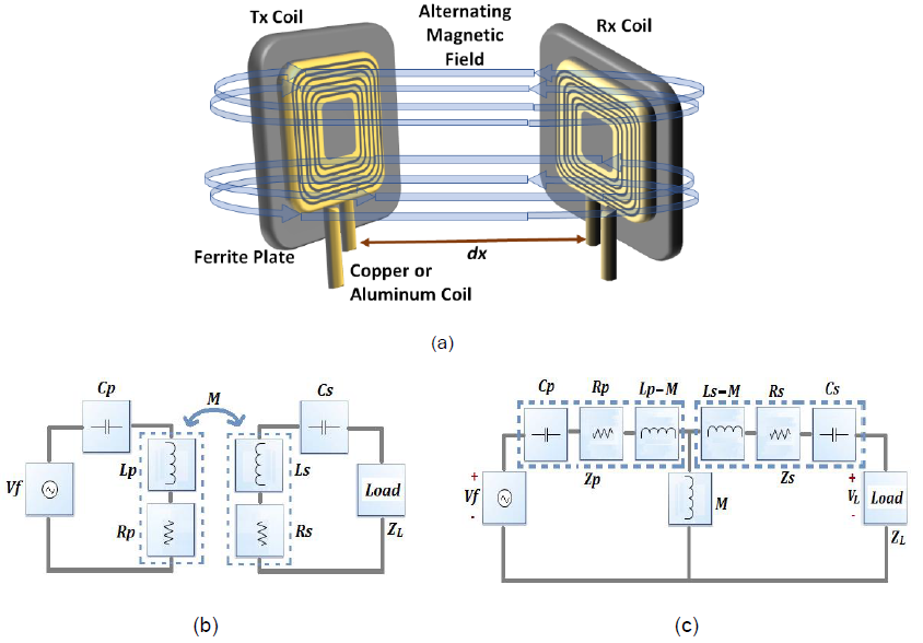
This principle is the same as the transformer with air core. The distance (dx) at which the energy can be transferred is increased by both coils resonating at the same frequency, since resonant coils can exchange energy efficiently; while no resonant interact only weakly.
Then based in the principle of transformer magnetic induction, WPT can be modeled using its equivalent circuit as show Figure 1b; as it can be notice capacitors Cp, Cs were connected in series with the impedance of Tx and Rx coil in order to compensate inductive reactance at the operating frequency.
Mutual inductance is noted with M, resistance and inductances for both sides (primary and secondary) are denoted with Rs, Ls, Rp, Lp respectively. Mutual inductance can be represented as an inductor between primary impedance Zp and secondary impedance Zs, by mutual coupling theory they are given by:
where w is angular frequency of the system given by the power source Vf. The resonance frequencies for both circuits' sides can be formulated as:
Since resonant coils can exchange energy efficiently, w is tuned to the resonant frequency of each circuit (w=w p =w s ) by selecting the appropriate tuning capacitance. For the analysis, the equivalent circuit of Figure 1c is considered as a two-port network, then from the mesh current equations written for magnetically coupled coils the system can be represented by:
In currents terms:
Once the currents are known, the power provided by the source (P f ) and the active power consumed by the load (P L ) can be calculated directly:
Load voltage can be obtained by:
substituting (7) in (6) and developing:
where X M is the magnetizing reactance that can be obtained from the mutual inductance M and coupling coefficient k:
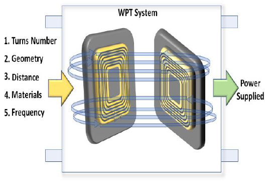
As the objective is to analyze the most relevant parameters for WPT then it is necessary to focus on the output power (8), as can be seen depends directly on the source voltage and the reactance of magnetization, inversely to the coil reactance's and resistances. As is known the resistances and reactance depend on the turns number, geometry and frequency, so these parameters affect the output power, another factor that indirectly impacts output power is the distance or separation of the coils, it affects the coupling factor since it depends on the relationship of the magnetic flux lines linking both coils.
Therefore, Figure 2 shows the identification of the parameters that affect the power of the load, the electromagnetic simulation was developed to determine the impact of these factors on the power that arrived at the load.
3 Electromagnetic Simulation with Finite Element Method
For simulation, COMSOL Multiphysics software was used, Electromagnetic waves and magnetic fields modules were used.
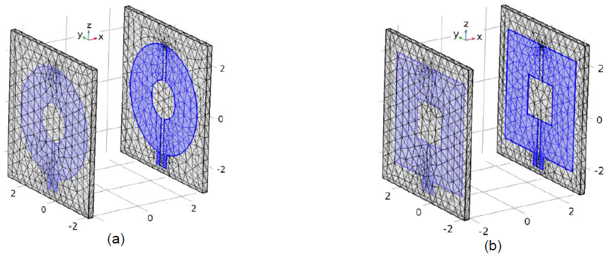
3.1 Turns Number and Geometry
To quantify the effect of the geometry on the output power of WPT, circular and square coils were modeled Figure 3, to make the comparison the diameter of circular coil was made to coincide with the size of the square coil. The number of turns affects the geometry dimensions, the greater turns number will increase coil width, or coil depth, or both. Also turns number affects reactance and resistance coils.
3.2 Distance
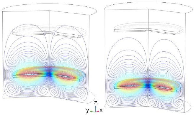
The distance affects the magnetic field links number, further away the coils are from each other, magnitude of magnetic flux links will be weaker, so distance affects the magnetic coupling given by:
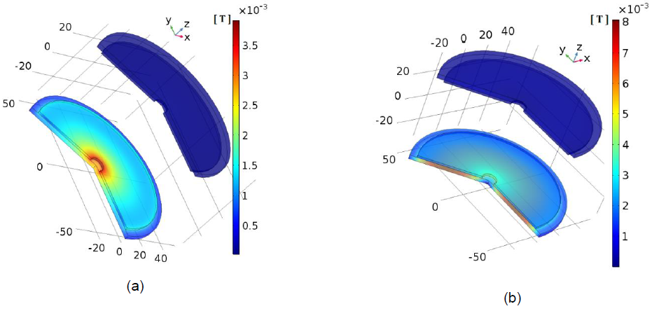
where ϕ ij is the magnetic flux lines produced by i linking j coil; Figure 4 shows comparison of the magnetic flux lines obtained between increasingly separate coils. More distance less magnetic flux lines in the receiver coil.
3.3 Materials
The assembly that supports the coils may or not be ferromagnetic material, currently this structure is manufactured by using a ferrite material plate, this ferrite properties (permeability and thickness) have influence to the maximal power transfer. Also a center magnet can be used to provide better alignment between the transmitter and the receiver coils.
Figure 5 shows comparison of the magnetic flux density without ferrite and with ferrite in assembly coils. Without ferrite in the coil assembly the magnetic field density (B) is lower than with using ferrite, without ferrite, B is concentrated in the inner periphery of the coil, while with ferrite, B is intensified thanks to ferrite permeability also B is expands throughout all coil assembly.
3.4 Frequency
Varying the operating frequency produce changes in reactance values, according to (8) this will affect the output power, so the big issue is to know what will be the operating frequency to maintain the output power values increasing the separation between coils, for that, it was used the relation given by [6]:
where wo is the optimal angular frequency to obtain the optimal coupling coefficient. The idea is to have (k/ko) close to one.
4 Results and Discussion
4.1 Numerical Simulation Results
Varying the distance of the coils Tx & Rx, turns number, materials, the output power (8) was determined by the electromagnetic simulation, the power ratio (output/input) is obtained in percentage and it is plotted versus the separation distance, Figure 6 shows graphically the summary of results obtained. N case means that the simulation contains the design values of the coils (original coils), those are contained in Table 1.
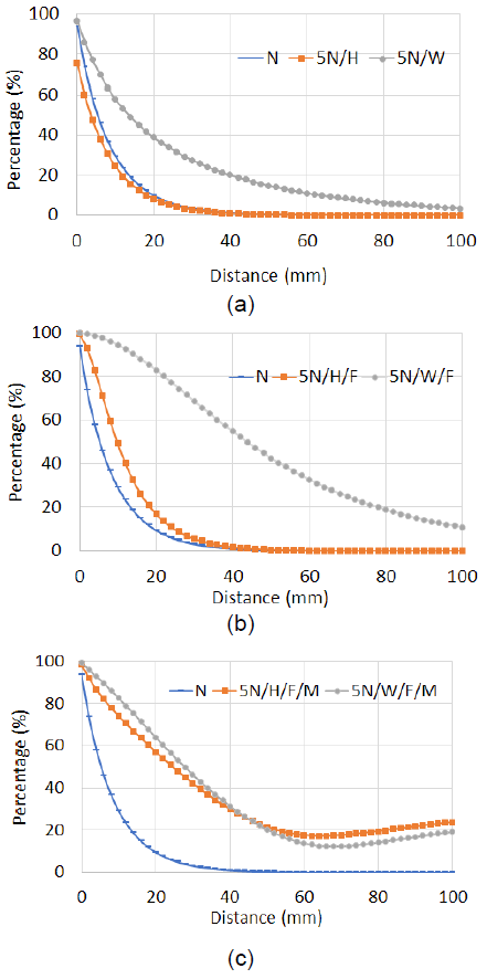
Fig. 6 Results (a) varying distance and number of turns. (b) adding ferrite material. (c) adding magnet
Table 1 Design Coil parameters
| Parameter | Value |
|---|---|
| Internal Diameter | 10 mm |
| External Diameter | 100 mm |
| Turns number | 30 |
| Conductor gauge | 15 AWG |
| Resistance AC | 0.086 Ω |
| Inductance | 32.728 μH |
| Power in Voltage AC | 100 V |
| Remanent Flux for Magnet | 1.2 T |
5N/H case means that coils have 5 times more turns that the original coil and they were growing in height H, in other words, the extra turns were stacked as solenoid. 5N/W case means coils grew in width, so they are flat coil configuration.
5N/H/F and 5N/W/F represents the same cases as above, but adding ferrite material. 5N/H/F/M and 5N/W/F/M represents the same cases as above, but adding magnet in the center of the coil.
The ring width is 45 mm, according with Figure 6a, after 45 mm of separation between the coils, the power transfer is null (less than 1%) in case N, also for the case 5N/H when there are 5 times more turns stacked to as solenoid coil.
The power transfer ratio in the case 5N/W is less than 1 % after 130 mm of separation between the coils because the turns number was increased in the ring width, therefore, the ring width dimension gives us an idea of the maximum separation between coils having at least 1% power transfer.
Figure 6b shows the results adding ferrite material, the cases N and 5N/H were not substantially affected, but the power transfer was improved more than 2 times in 5N/W.
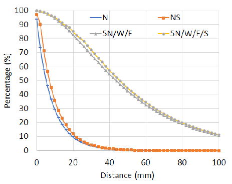
Figure 6c shows the results adding a magnet in the center of the coil. It is possible to note that power transfer percentage was improved for both solenoid and flat coil cases (5N/H & 5N/W respectively). It can even be seen that the power transfer is 20% beyond the size of the ring width. Therefore, adding ferrite and a magnet in coil assembly are relevant parameters that improve the power transfer and it is not easy to quantify by analytical equation as (8).There are no significant changes comparing the use of circular or square coils (N or NS respectively), the results obtained for the different cases were very similar, see Figure 7. It can be observed that using square coils improves power transfer slightly, since it has a transfer area light larger than a circular coil. In addition, this geometry issue is not easy to quantify by analytical equation as (8).
4.2 Model for Coupling Coefficient
From the large number of results obtained through the variation of coils separation and by curve analysis, it was possible to obtain an approximate model of the coupling coefficient. For this our theoretical framework was based on the hypothesis, that power transfer less than 1% is obtained with a separation of coils close to transfer coil width, therefore the coupling coefficient is able to approximate according to the coil width (W dc ) separation between coils (d x ). It is given by:
where k b factor could be obtained by:
where W dc and d x must be in millimeters.
Figure 8 shows the change in operating frequency as the distance between coils increases, three cases can be observed, with nominal turns N, with 2N (double) turns stacked in the coil width, with 5N turns. It is possible to notice that larger the coil, the operational frequency to improve output power is reduced, with smaller coils the operating frequency rises beyond kilohertz.
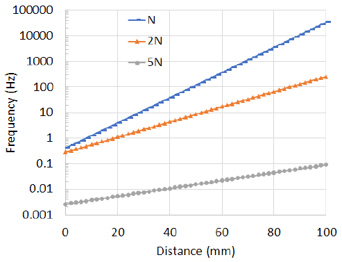
Figure 8 could be obtained thanks to the model of the coupling coefficient obtained, it is also possible to apply this model in (8) to obtain the output power by varying the distance without using a numerical simulation.
6 Conclusions
In the future, more electrical machinery and electronic devices with medium power demand (kilowatts order) will be powered wirelessly, therefore it is convenient to be prepared with tools and design methods for wireless power transfer robust system, this work quantifies by numerical simulation the impact on output power changing the separation between the transmitter coil and receiver, materials, geometries and number of turns. These changes in relevant parameters to improve wireless power transfer, it is not easy to do it, by analytical equation however the quantifies obtained allowed to determine a model for coupling coefficient to compute optimal frequency for the power transfer without the need to use a numerical simulation, hence this document contributes to identify the important parameters to be controlled or modified in the coils with the goals to optimize the power transmission for a wireless system.

