


Services on Demand
Journal
Article
 text in
  English (pdf)
 Article in xml format
 Article references
 Send this article by e-mail
Indicators
-
 Cited by SciELO
 -
 Access statistics
Related links
-
 Similars in
SciELO
Similars in
SciELO
Share

 Permalink
Revista ALCONPAT
On-line version ISSN 2007-6835
Rev. ALCONPAT vol.6 n.2 Mérida May./Aug. 2016
https://doi.org/10.21041/ra.v6i2.136
Applied research
Fire resistance of pultruded profiles of glass fiber reinforced polymer (GFRP) for rehabilitation applications: experimental, numeric, and analytical study
1CERIS, Instituto Superior Técnico, Universidade de Lisboa, Portugal.
2CERIS, Instituto Superior Técnico, Universidade de Lisboa, Portugal.
3LAETA, Instituto Superior Técnico, Universidade de Lisboa, Portugal.
This paper presents a study about the fire behaviour of glass fibre reinforced polymer (GFRP) pultruded beams. Fire resistance tests were carried out in beams with a span of 1.3 m, exposed to fire according to the time-temperature curve defined in the ISO 834 standard. In these tests the effects of different types of fire exposure (one and three sides) and load levels, as well as the efficacy of different fire protection systems were evaluated. In order to study the evolution of temperature distributions during the fire resistance tests, a two-dimensional numerical model was developed using the commercial software ANSYS FLUENT. Also an analytical model was developed to estimate the mechanical response of the beams during fire exposure.
Keywords: composite materials; fire behaviour; experimental campaign; numerical simulation; analytical model
Neste artigo é apresentado um estudo sobre a resistência ao fogo de vigas em perfis pultrudidos de polímero reforçado com fibras de vidro (GFRP). Foram realizados ensaios de resistência ao fogo em vigas com um vão de 1.3 m, expostas ao fogo de acordo com a curva temperatura-tempo da norma ISO 834. Nestes ensaios, avaliou-se o efeito de diferentes tipos de exposição ao fogo (em uma e três faces) e níveis de carga aplicados, bem como a eficácia de diferentes sistemas de proteção. Foi desenvolvido um modelo numérico térmico bidimensional no software ANSYS FLUENT para simular a evolução das distribuições de temperatura na secção transversal. Foi ainda desenvolvido um modelo analítico para determinar a evolução das deformações das vigas.
Palavras-chave: materiais compósitos; resistência ao fogo; campanha experimental; simulação numérica; modelo analítico
El presente artículo presenta un estudio sobre la resistencia al fuego de vigas fabricadas con perfiles pultrusionados de polímero reforzado con fibra de vidrio (GFRP). Se realizaron ensayos de resistencia al fuego en vigas con un vano de 1.3 m, expuestas a la acción del fuego según la norma ISO 834. En estos ensayos, se evaluó el efecto de diferentes tipos de exposición al fuego y los niveles de carga aplicados, así como la eficacia de diferentes sistemas de protección. Se desarrolló un modelo numérico en el software ANSYS FLUENT para simular la evolución del campo de temperaturas en la sección transversal y un modelo analítico para determinar la evolución de la deformación de las vigas.
Palabras clave: materiales compuestos; resistencia al fuego; campaña experimental; simulación numérica; modelo analítico
1. Introduction
The use of Fiber Reinforced Polymers (FRP) is increasing each day for applications in civil engineering as they bring along different advantages in relation to the materials that are traditionally used in this sector, among which are the reduced weight, high resistance, good thermal isolation properties, reduced maintenance fees, and excellent durability. Despite having a fragile behavior and a high deformability, these composite materials present a deficient behavior to fire, which considerably limits their practical application, especially in buildings (Correia, 2012).
When the FRP are exposed to moderately high temperatures (100-200 ºC), they soften and their mechanical properties (rigidity and resistance) are considerably reduced. When the materials are exposed to high temperatures (300-500 ºC), the polymeric matrix decomposes, releasing heat, smoke, soot, and toxic volatile gases (Correia, 2004). Presently, type-E glass fibers are most commonly used for the reinforcement of FRP (80-90% of commercial products) (Samanta et al., 2004). These fibers start softening and become viscous at temperatures close to 830 ºC, presenting a melting point of around 1070 ºC (Mouritz et al., 2006). In this manner, the polymeric matrix is what essentially conditions the behavior of the FRP at high temperatures.
The mechanical properties (rigidity and resistance) in the compression and cutting of the GFRP material (more dependent on the matrix) are more affected by the increase of temperature than the traction properties (which are more dependent on the fibers) (Correia et al., 2013), which results in the collapse of beams with GFRP to occur usually due to compression and/or cutting and not due to traction. Regarding the behavior of beams with GRFP to fire, Ludwig et al. (2008) carried out fire resistance tests on beams with an I-section (IPE 120 and IPE 160 profiles) exposed to fire in four stages. Similarly, Correia et al. (2010) evaluated the performance of GFRP beams with a tubular square section for an exposure to fire of just one stage. In both studies, the composite beams were comprised by a polymeric matrix with a polyester resin and by type-E glass fibers, which were exposed to fire according to the fire curve pattern defined in the ISO 834 (1999) standard. In both experimental procedures, different systems of fire protection were studied.
In this article, we present a study on the behavior to fire on beams with pultruded profiles of GFRP. The main objective of the experimental program that was developed was to evaluate the resistance to fire of the GFRP beams in terms of the type of exposure to fire and the two levels of load that are applied, evaluating the efficiency of different protection systems. With the objective to simulate the evolution of the temperatures in the GFRP section that is subject to a fire situation, a bi-dimensional model was developed using the commercial software ANSYS FLUENT (ANSYS, 2012), in which the changes in heat by conduction, radiation, and convection were considered accounting for the air in the interior of the cavity of the section. Simultaneously, an analytical model was also developed, through which the evolution of the arrow in the middle of the span of a GFRP beam was estimated throughout the study.
2. Experimental study
2.1. Experimental procedure
In the fire resistance tests, the pultruded GFRP, with a square tubular section (100×100×8 mm), produced by the Fiberline company, was evaluated. This material is comprised by rovings of type-E glass fibers in the central zone of the laminations and by two layers of continuous stand mats positioned randomly, which surround that central layer of the lamination. The compound is comprised of 69% inorganic material and the glass fibers are embedded by a polyester resin matrix. Dynamic Mechanical Analysis (DMA) tests were done on the GFRP material, which showed that its vitreous transition temperature (Tg, determined through the mean point of the curve of the storage module) is of 140 ºC. Differential Scanning Calorimetry and thermogravimetric analysis (DSC/TGA) tests were done, where the decomposition temperature (Td) of the material at approximately 370 ºC was determined (Morgado et al., 2013).
To increase the fire resistance of the GFRP beams analyzed, six different protection systems were implemented. The protection materials used in this experimental procedure were the following: plates of cork agglomerate (CA), from the Robcork company (25 mm in thickness); Plates of Rock Wool (RW), facilitated by the Rockwool company (25 mm in thickness); plates of calcium silicate (CS), manufactured by the Promatec company (H type, 25 mm in thickness); absorbent blanket (MI), delivered by Technical Fibre Products (Tecnofire 60853A, 2 mm in thickness); and absorbent dye (TI), from CIN (C-THERM HB, 2 mm in thickness). An active protection system through water cooling (AA) was also used, which consists on sheet of water 8 mm thick on the lower part, with a flow rate of 0.4 m3/h. The protection plans applied are shown in Figure 1.
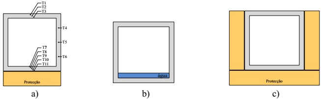
Figure 1 (a) Beams with passive protection exposed to one face (indicating the position of the thermocouples); (b) beams with active protection exposed to a third of the face(s); and (c) beam with passive protection exposed on the three faces.
In this experimental procedure, 12 beams with a square tubular section were tested; they were grouped into three experimental series. In the S1series, the beams were exposed to fire on just one face (E1F) and subject to a service load equivalent to one arrow in the middle of the span of L/400 (room temperature). In the S2 series, the beams were exposed to fire on the three faces (E3F) and were subject to a load that was equal to that of the first series. In the S3 series, the beams were also exposed to the fire on just one face, being subject to a load equivalent to one arrow in the middle of the span of L/250 (also the room temperature). It is also important to point out that a non-protected (NP) beam was tested in each of the series, as presented on Table 1.
Table 1 Experimental procedure
| Series | Number of beams | Designation of the beams | Exposure to fire | Apllied Strength [kN] |
|---|---|---|---|---|
| S1 | 7 | NP-S1, AC-S1, LR-S1, SC-S1, MI-S1, TI-S1, AA-S1 | E1F | 11.7 |
| S2 | 3 | NP-S2, SC-S2, AA-S2 | E3F | 11.7 |
| S3 | 2 | NP-S3, SC-S3 | E1F | 18.7 |
The fire resistance tests were done in a vertical gas furnace (Figure 2a), with external dimensions of 1.35×1.20×2.10 m (length × width × height), that has an open space on top allowing the test of horizontal elements. These tests were done by adopting the fire curve pattern defined on the standard ISO 834 (1999), presented in Figure 3c. In the S1 and S3 series, the GFRP beams were exposed to fire on only one face, whereas in the series S2, the beams were exposed to fire on three faces, as illustrated in Figure 1b. The different types of exposure to fire were obtained through a system of covers, comprised of different modules that allow the exposure to fire on one or three faces. The beams were tested in terms of flexion on four points with the free span between supports of 1.3 m, applying different loads in accordance with the experimental series. As illustrated in Figure 2a, the weights used for loading the beams were materialized through concrete elements and cement bags.
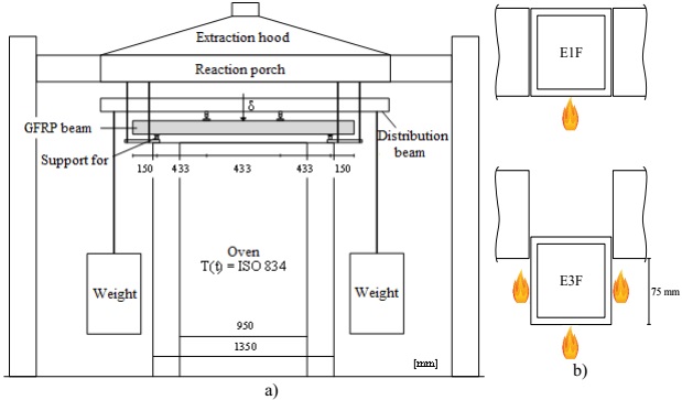
Figure 2 (a) E-test plan and (b) types of expositions tested, on one face (on) and on the three faces (below).
The GFRP beams were instrumented with type K thermocouples, through which it was possible to register the temperatures in the cross-section in the middle of the span, installing three thermocouples on the above face (T1-T3), three thermocouples in the web (T4-T6), and five thermocouples on the face (T7-T11). The positioning of the thermocouples installed on the upper and lower faces was done to obtain the evolution of the temperatures along the length of the width of the walls. As for the position of the thermocouples that were installed on the webs, they were placed to allowed the evaluation of the temperatures throughout the web as illustrated in Figure 1a. After the placement of the thermocouples in the planned positions, the corresponding protection systems were implemented. In the middle of the span of the GFRP beams, a thread deflectometer of the TML brand (model CDP-500) was fixed, through which the evolution of the arrows of the beams was monitored.
2.2 Results and discussion
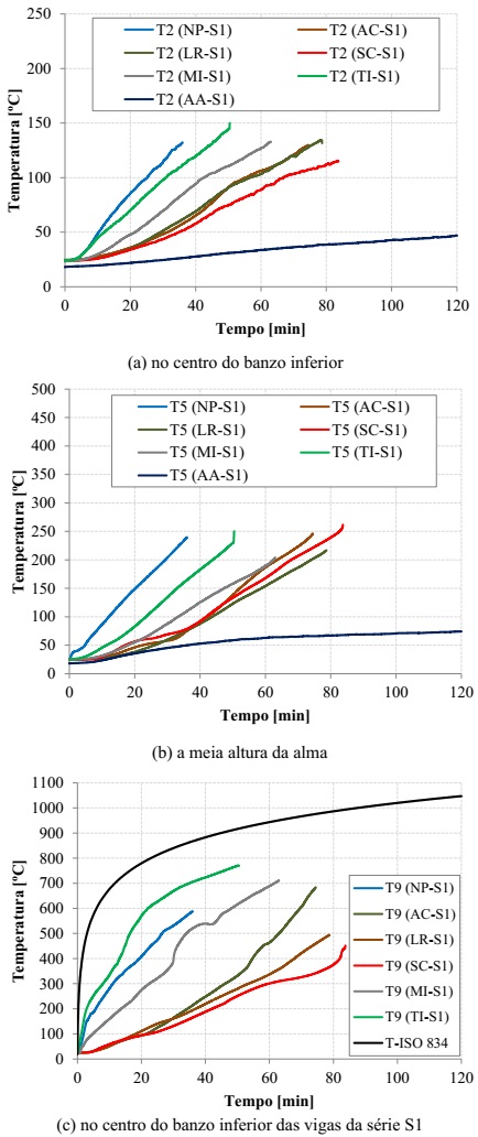
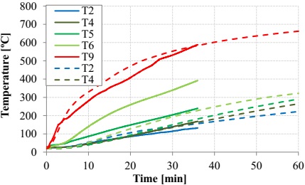
To evaluate the temperatures observed in the different fire resistance tests, the temperatures at medium height of the upper face (T2), of the web (T5), and of the lower face (T9) were observed. Figure 3 shows the evolution of the temperatures registered on the beams of the S1 series. As expected, the implementation of fire protection allowed the improvement of the thermal performance of the GFRP beams, i.e., it helped delay the heating of the cross-section. In fact, the implementation of protections helped significantly reduce the temperatures in comparison to the non-protected beam (NP-S1); the efficiency of cork, rock wool, and calcium silicate agglomerate protections, as well as cooling with water stand out, with this last system being the most efficient in protecting the web and the upper face. It is important to point out that, in the S1 series, the collapse of the beams took place when the average temperature of the upper face was close to the vitreous transition temperature (Tg) of the GFRP material (Figure 3a).
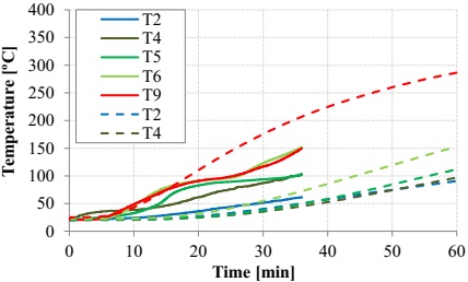
Figure 4 presents the comparison of the evolution of the temperatures on the non-protected and protected beams with calcium silicate of the S1 and S2 series (in the case of NP beams, the values presented were measured in auxiliary profiles, not subject to any load; the temperatures measured on the AA-S2 beam are not presented, as the duration of this test was too short). In the case of the beams of the S2 series, the fact of the temperature evolution curves of the webs and that the lower faces are so similar stands out, which is consistent with the type of fire exposure of these beams (three faces). As in the S1 series, the passive protection with calcium silicate allowed reducing the temperatures in a significant manner. In the beams of the S3 series, as expected, the evolution of the temperatures was very similar to the one recorded in the S1 series, which was due to the thermal exposure being identical (one face).
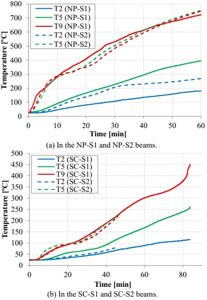
Figure 5a shows the variation on the displacements in the middle of the span of the beams of the S1 series, in terms of the test duration. In the beams without passive protection, a rapid increase of the arrow in the middle of the span was seen during the initial instants; which is be related to the fast degradation of the mechanical properties of the lower face. After this initial phase, the range of deformation in these beams decreased, staying reasonably constant until the end of the test-a height at which it increased again in an increasing tendency. In the beams with passive protection, the increase of deformation with time (which varies for the different protections) was less marked, which is naturally associated to a slow and gradual heating of the cross-section and, consequently, resulting in a lower reduction of the mechanical properties of the GFRP material. In the case of the beam with active protection, despite the initial increase of deformation being relatively fast (which is associated to the fact that the lower face does not have any protection), after a certain height, a estabilization of the evolution of the arrow in the middle of the span was verified, which presented a very reduced growth rate until the end of the exposure to fire. Figure 5b shows the comparison between the variation of the displacements in the middle of the span of the beams of the S1 series with the S2 and S3 series. As expected for the same type beams, the exposure to three faces (S2 series) and the increase of the load (S3 series),caused greater increases in the deformations.
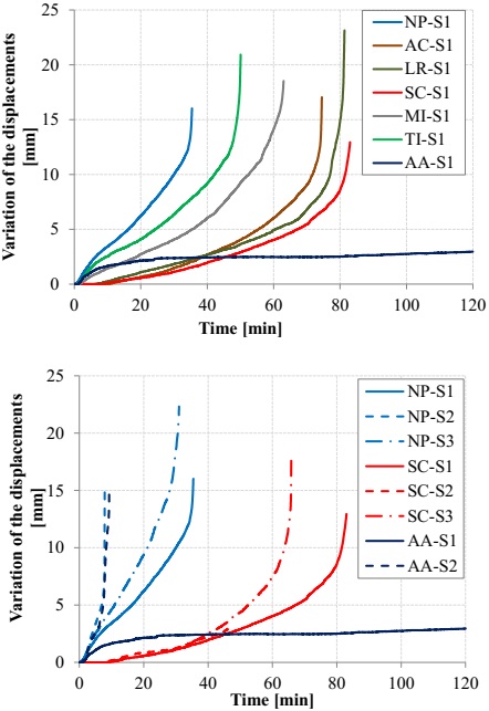
Figure 5 Mechanical response: variation of the displacements recorded in the middle of the span of the beams (a) of the S1 series and (b) of the S1, S2, and S3 series, non-protected (NP), with calcium silicate (CS) and cooled with water (AA).
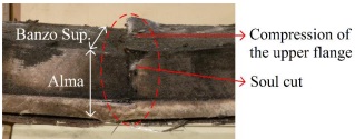
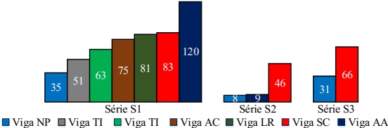
In relation to the manner of breakage, all beams collapsed in a fragile manner and without any signs of pre-breaking. The general portions of the beams collapsed due to the longitudinal compression of the upper part in the central zone and/or due to transversal compression and the cutting of the webs over one of the load application points, as illustrated in Figure 6. The beams of the S2 series (exposed to fire on three faces), non-protected and cooled with water, seem to have collapsed due to the cutting/instability of the webs, which presented a very significant arching throughout their entire height. In addition, it is indicated that the beam cooled with water and exposed to fire on the lower face (AA-S1) did not collapse for 120 minutes, point at which the test was interrupted. In Figure 7, a comparison between the fire resistance times of the different beams is presented, highlighting (i) the efficiency of the different protection systems and the reduction of the fire resistance caused (ii) by the exposure on three faces, and especially for the system cooled with water (the efficiency of which is drastically decreased), and (iii) by the increase of the load.
3. Numeric study
3.1 Numeric model
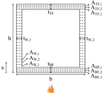
With the intention of simulating the fire resistance tests that were carried out, a bi-dimensional thermal model was developed, using the commercial software ANSYS FLUENT (ANSYS, 2012), to simulate the evolution of the temperatures on the exposed tubular section beam exposed to fire on one face and not protected (NP-S1 beam). In the model developed (Figure 8a) the following hypotheses were considered: (i) the furnace transfers heat to the lower part of the profile through radiation (ε = 0.70) and convection (h = 25 W/m2); (ii) the transfer of heat in the profile occurs through conduction in the GFRP material, as well as through internal radiation (ε = 0.75) between the faces of the cavity of the profile and through the convection of the air contained; (iii) the webs are adiabatic surfaces; and (iv) the upper part transfers the heat to the external atmosphere through convection (h = 10 W/m2) and radiation (ε = 0.75).
For the net used discretize the 100×100×8 mm cross-section, quadrangular elements (Quad_4) with a side of 1 mm (for the solid material and the air flow) were used, as illustrated in Figure 8b, which resulted in a net with 10 000 elements and 10 201. For the thermal properties (Table 2), the following hypotheses were considered: (i) for air, it was considered that the density, specific heat, thermal conductivity, and cinematic viscosity vary with temperature (Engineering Toolbox, 2015); (ii) for the GFRP material, it was assumed that the density, specific heat, and thermal conductivity vary with temperature, according to Bai et al. (2007). An analysis with a total duration of 3600 s was carried out with a time step of 1 s.
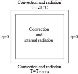
Table 2 Thermal properties considered.
| Properties | GFRP4 (20-1000 ºC) | Ar5 (20-1000 ºC) |
|---|---|---|
| Density [kg/m3] | 1890-1351 | 1.21-0.28 |
| Specific heat [J/kg.ºC] | 1053-877 | 1005-1185 |
| Conductivity [W/m.ºC] | 0.35-0.10 | 0.03-0.08 |
| Viscosity [kg/m.s] | - | 1.85-4.79 (×10-5) |
4 (Engineering Toolbox, 2015), 5 (Morgado et al., 2013)
In addition to the abovementioned simulation of the evolution of the temperatures for a non-protected beam and exposed to fire on one face (E1F), the thermal response was also estimated for a beam protected with calcium silicate (CS) for E1F. For this, it was barely necessary to alter the geometry of the model and add a new material, as the exchanges of heat between the protection with CS and the GFRP profile happen through conduction. According to the information obtained through the facilitator of the material, the thermal properties of the CS (density, specific heat, and conductivity) were considered as variable with the temperature.
3.2 Numeric vs. Experimental results
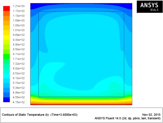
Figure 9 presents, in an illustrative manner, the numeric distribution of temperatures in the cross-section of the NP-S1 beam after and during 30 minutes of exposure to fire. Figure 10 shows the comparison of the experimental temperatures measured in the NP-S1 beam with the corresponding values obtained through the numeric model. It is confirmed that, globally, the numeric curves are consistent with the ones obtained experimentally, particularly on the upper (T2) and lower (T9) parts. The considerably higher values of experimental temperatures measured in the web (T4, T5, and T6), especially in their lower zone (T5 and T6), could be associated to an eventual isolation lateral deficit of the lower part of the webs, which may not have been completely efficient.
For the beam protected with SC, the temperature distribution in the section is presented in Figure 11. Comparing the temperatures experimentally obtained with the ones numerically obtained, it was observed that the numeric temperatures in the web (T4-T6) were, once more, inferior to the experimental ones, as illustrated in Figure 12; this could be related to an eventual deficient lateral isolation of the profile. The evolution of the numeric temperatures in the upper frame face (T2) was comparable to the experimental ones. However, in the lower face (T9), despite the numeric and experimental temperatures presenting a similar magnitude, it is possible to observe some differences regarding the increase tendencies of the temperature (increase rate throughout the test). This seems to be related to the thermal properties considered for the CS (provided by the manufacturer), which may not reproduce the real behavior of the material with enough precision.

4. Analytical study
4.1 Analytical model
In the analytical study, a model was developed to simulate the mechanical response registered in the fire resistance tests, particularly to determine the evolution of the displacements in the middle of the span of the beams in relation to the time of exposure to fire. The analytical model developed is based (i) on an analysis of the section through the slice method, which, for each instant of time, is considered the variation of the mechanical properties of the GFRP material with the temperature, and (ii) at the beginning of the virtual works, applying the Timoshenko beam theory (Bank, 2006), that is, taking into consideration the deformability through flexion and the deformability through cutting.
As with the Mouritz study (2003), the cross-section of the GFRP beam was divided into several layers as illustrated in Figure 13. Subsequently, a temperature was attributed to each one of the layers for each instant of time, this attribution can be done through the experimental tests or through the thermal numeric model described in the previous section. Based on the temperature of each layer, the corresponding modules of elasticity and compression (EC), the traction (ET), and the distortion module (G) were determined. The variation of these mechanical properties in relation to the temperature was estimated based on the tests carried out at the Instituto Superior Técnico (Correia et al., 2013). It is important to note that the position of the neutral axis (xLN) was calculated for each instant of time, through which the flexural rigidity of equivalent flexion (EIeq) of the section was calculated. To determine the rigidity of the cut (GmAv), a mean distortion module (Gm) was calculated for each instant of time. Otherwise, Gm was calculated through a ponderation between the distortion module on each slice and the areas of the same (Gm=∑GiAi/∑Ai). Regarding the cut area (Av), it was considered that the same is constant (Av= k×A, A being the area of the section and k the cut coefficient). Once the parameters EIeq and GmAv have been estimated, the displacement (δ) in the middle of the span of the beam is obtained through the principle of virtual works, using equation (1) which takes into consideration the parcels of deformation by flexion and deformation by cutting:
4.2 Analytical vs. Experimental results
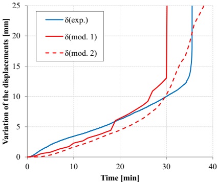
The aforementioned model was implemented to estimate the evolution of the displacements in the middle of the span of the NP-S1 beam, with a tubular section and exposed to fire on one face. Figure 14 shows a comparison between the variation of the displacements in the middle of the span measured in the resistance to fire tests and the corresponding values obtained through the analytical model, considering the temperatures that were experimentally measured (model 1) and the ones calculated numerically (model 2). It can be observed that, globally, the analytical model developed offered a good approximation to the experimental results, considering the temperatures measured experimentally (mod. 1 curve) and the numerically calculated temperatures (mod. 2 curve). In both cases, despite the model having offered variations of displacements that are slightly inferior to the ones experimentally measured during the initial part of the thermal exposure, the same was able to reproduce the progressive increase of the arrow in the middle of the span before the collapse and also presented relatively precise estimations (given the complexity of the phenomena that intervenes) in the experimental fire resistance (35 minutes) of the beam - 30 minutes (model 1) and 31 minutes (model 2). It is worth pointing out that the analytical curves represented in Figure 14 show a less regular development than the experimental one, especially in model 1. This is due (i) to the finite number of layers considered and, overall (ii) to the variations of the different mechanical properties of the GFRP material with the temperature considered in the models, which represent constant values for certain intervals of temperature (Correia et al. 2013). In the case of model 1, it emphasizes the fact of having considered a smaller number of temperatures than in model 2.
5. Conclusions
The experimental procedure showed that the different protection systems allowed for the considerable improvement of the behavior to fire of the GFRP beams. It was observed that the most efficient protection materials were the cork agglomerate, rock wool, and calcium silicate. It is important to point out that, for the exposure on one face, the cooling solution using water was clearly the most efficient, making the fire resistance time greater than 120 minutes. It was also seen that the exposure of three faces and the increase of the service load caused significant reductions on the fire resistance time. The experimental tests carried out also helped to confirm that the pultruded profiles of GFRP, when exposed to high temperatures, are more vulnerable to compression and cutting than to traction. In fact, for most of the tests, the collapse of the beams happened due to the longitudinal compression of the upper face and/or due to the compression or cutting of the webs. The beams exposed to fire on three faces without passive protection presented a collapse mechanism by cutting with the arching of the web.
The thermal numeric model (bi-dimensional) developed using the commercial software ANSYS FLUENT, made it possible to evaluate the distribution of temperatures on the beams exposed to fire on one face, both non-protected and protected with CS. In this model, both the heat exchange between the solid (GFRP and CS) and the external environment (by radiation and convection) and the heat exchange between the solid and the air (fluid) in the interior of the cavity by convection, as well as by radiation between the internal walls of the section, were considered. A reasonable consistency between the experimental and the numeric curves regarding the temperature of the upper and lower faces was obtained. The webs registered relatively significant differences, which could be explained by a deficient lateral isolation between the GFRP profile and the covers of the furnace.
The analytical model developed made it possible to estimate the evolution of the displacements in the middle of the span of the non-protected beam exposed to fire on one face. In this model, the cross-section of the beam was divided into layers, which were attributed to different temperatures corresponding to the times of exposure to fire and, consequently, to different mechanical properties regarding traction, compression, and cutting. For each instance of time, the arrows in the middle of the span were calculated through the Timoshenko beam theory. A good consistency was obtained between the variation of the displacements with the time and relatively precise estimations of the fire resistance times.
6. Acknowledgements
The authors would like to thank FCT (PTDC/ECM/100779/2008 project) and the ICIST for financing the investigation. The first author is grateful to FCT for the doctorate scholarship that was granted to him SFRH/BD/94907/2013.
REFERENCES
Correia, J. R. (2012), “Materiais compósitos de matriz polimérica”, em Ciência e Engenharia dos Materiais de Construção, IST Press, Lisboa. [ Links ]
Correia, J. R. (2004), “Perfis pultruidos de polímero reforzado com fibras de vidrio (GFRP). Aplicação de vigas mistas GFRP betão na construção”, Dissertação de Mestrado em Construção, Instituto Superior Técnico, Universidade Técnica de Lisboa. [ Links ]
Samanta, A. et al. (2004), “Thermo mechanical assessment of polymer composites subjected to fire”, The Robert Gordon University, Aberdeen. [ Links ]
Mouritz, A. P., Gibson, A. G. (2006), “Fire properties of polymer composite materials”, Springer, Dordrecht. [ Links ]
Correia, J. R. et al. (2013), “Mechanical behaviour of pultruded glass fibre reinforced polymer composites at elevated temperature: Experiments and model assessment”, Composites Structures, V. 98, pp. 303-313. [ Links ]
Ludwig, C. et al. (2008), “Thermal and Thermo mechanical Investigation of Polyester based Composite Beams”, Fourth International Conference on FRP Composites in Civil Engineering, Zurich. [ Links ]
Correia, J. R. et al. (2010), “Fire protection system for building floors made of pultruded GFRP profiles. Part 1: Experimental investigations”, Composites: Part B, V. 41, pp. 617-629. [ Links ]
ISO 834-1 (1999), Fire resistance tests. Elements of building construction - Part 1: General requirements, International Standards Organization, Genève. [ Links ]
Software comercial ANSYS FLUENT, ANSYS, inc, versão 14.2, (2012). [ Links ]
Morgado, T. et al. (2013), “Comportamento ao fuego de vigas de compósito de GFRP”, Revista Internacional Construlink, nº 32, pp. 4-19. [ Links ]
Website, http://www.engineeringtoolbox.com/dry-air-properties-d_973.html, (2015). [ Links ]
Bai, Y., Vallé, T., Keller, T. (2007), “Modeling of thermos physical properties for FRP composites under elevated and high temperature”, Composites Science and Technology, V. 67, pp. 3098-3109. [ Links ]
Bank, L. C. (2006), “Composites for construction: Structural design with FRP materials”, Wiley, Hoboken. [ Links ]
Mouritz, A. (2003), “Simple models for determining the mechanical properties of burnt FRP composites”, Materials and Engineering, V. 359, pp. 237-246. [ Links ]
Received: December 29, 2015; Accepted: April 01, 2016
 Este é um artigo publicado em acesso aberto sob uma licença Creative Commons
