


 text new page (beta)
 English (pdf)
 Article in xml format
 Article references
 Send this article by e-mail
 Cited by SciELO
  Similars in
SciELO
Similars in
SciELO 
 Permalink
1. Introduction
Currently, there are many software systems and environments that allow you to simulate and perform fairly complex and voluminous calculations associated with dynamic effects on structural elements of overpasses. At present, in almost all software systems that perform calculations for strength, rigidity and stability, the finite element method (FEM) is implemented as the main tool for computer modeling (Alekseev et al., 2019; Gorga et al., 2018; Kromoser et al., 2020; Li et al., 2019). This method allows you to clearly understand the design of the structure, its movement and determine the forces in the structure under the influence of various loads or influences.
One of the advantages of the method is determined by the ability to increase the strength characteristics of the structure while optimizing the cost of materials and production. This is achieved through the use of spatial analysis technologies, taking into account the physical nonlinearity of materials, structural, geometric and genetic nonlinearity of the structure (Kasyanov et al., 2019; Skvortsov et al., 2018; Panchenko, 2018; Skvortsov et al., 2014). The guarantee of error-free modeling and, as a result, adequate calculation results is the professional training of the calculator, its practical experience, as well as the use of modern computer-aided design programs and BIM technology (Barabanshchikov et al., 2016; Makarenko & Kuznetsova, 2019; Pan et al., 2018; Umnova et al., 2018).
Depending on the tasks, in the work you can use such software systems: LUSAS (Great Britain); GTSTRUDL (USA); MIDAS/CIVIL (Korea); RM BRIDGE (Austria); SOFISTIK (Germany); LIRA (Ukraine); ANSYS, NAUSTRAN, SCAD, KATRAN, Tekla (Russia) and many other complexes that allow you to build finite-element computational models of artificial structures with minimal labor and time, for design engineers (Babaytsev et al., 2017; Babaytsev et al., 2019; Cabana et al., 2018; Gendler & Savenkov, 2017).
The advantage of using finite element models is the ability to simulate various malfunctions in the design, adapting the calculation results to actual operating conditions. By the deviation of the calculated values of the amplitude-phase-frequency characteristics (APFC) from the normative, one can judge the degree of damage to the span structures of the railway bridge. In the Tekla PC developed by I.V. Nesterov there are certain developments in this direction, when creating a calculation model, an extensive library of structural units is used, which allows you to elaborate and analyze the exploitable designs of railway bridges in detail (Smirnova & Aung, 2017; Yazdani & Azimi, 2020).
2. Materials and methods
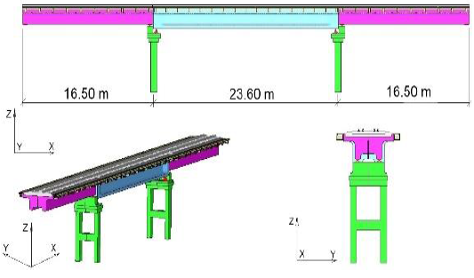
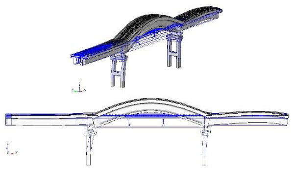
The article considers the results of a modal analysis of a reinforced concrete railway overpass as a whole and its elements separately. The design scheme of the overpass 16.50 + 23.60 + 16.50 m (Fig. 1).
Let’s get the data for the calculation. We will consider the following design case - “Tension reinforcement blocks 23.6 m + dead weight”. The forms and frequencies of natural vibrations of the structure were calculated under preliminary loading with constant loads - “Tension of the reinforcement of the blocks 23.6 m + Net weight”, using the experience of contemporaries (Groshev, 1999; Kataev, 1984; Rupasova & Kondratov, 2012; Shaposhnikov et al., 1986; Verma & Nallasivam, 2020). The results of the calculation model of the overpass (FEM) are presented in Figures 2-6 (modal analysis).
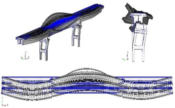
Mode 1. The first transverse bending mode of vibration is a bending form with one “antinode” in the plane of the path (transverse bending). Accent is the portion of a standing wave in which the oscillations have the greatest amplitude. I consider it to be the first bend in the plane of the path (i.e., not in the vertical plane), the frequency is 4.56 Hz (Fig. 2).
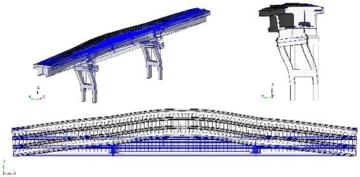
Mode 2. The first vertical bending form is a bending form for a 23.6 m span with one “antinode” in the vertical plane. I consider it the first to bend in the vertical plane (i.e., not in the plane of the path), the frequency is 6.00 Hz (Fig. 3).
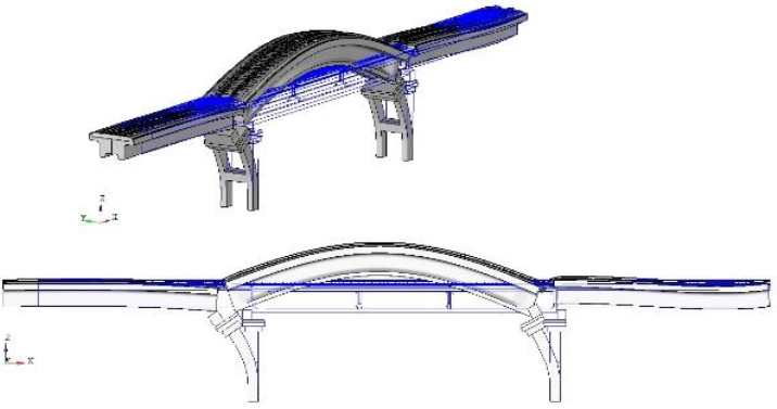
Mode 3. The second transverse bending mode of vibration is a bending form with two “antinodes” in the plane of the path. It is similar to “Mode 1”, so the second transverse bending in the plane of the path, the frequency of 7.67 Hz (Fig. 4).
Mode 4. The second vertical bending form is very similar in appearance to “Mode 1”. Noticeable differences are, perhaps, only in the direction of inclination of the support frames with the same form of bending of the span 23.6 m, “antinode” up, frequency 7.92 Hz (Fig. 5).
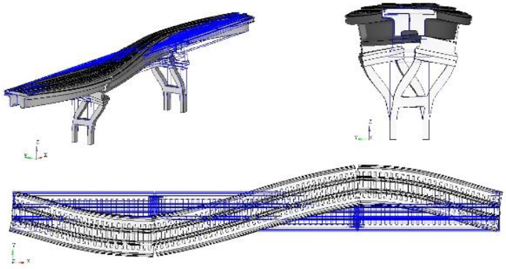
Mode 5. Complex vibrational mode (torsional) a 23.6 m span is twisted around a certain longitudinal axis, while in the top view one “antinode” is distinguishable from bending in the plane of the path, the frequency is 9.15 Hz (Fig. 6).
Thus, the oscillation frequencies detected by the calculation do not fall into the forbidden set of rules (Set of rules No. 35.13330, 2011) in the interval of less than 0.67 Hz.
3. Results and discussion
Experimental and theoretical data were obtained on beam reinforced concrete spans by the following authors (Agrati, 1994; Aktan et al., 1994; Aktan, 1995; Bondar et al., 2016; COSMOS/M User Manual Version 1.75, 1996; Kvashnin et al., 2015a; Kvashnin et al., 2015b). The data obtained in the calculations of the beam spans of the railway overpass according to the forms (modes) and frequencies of natural vibrations are summarized in Table 1.
Table 1 Forms and frequencies of natural vibrations of building blocks.
| Overpass by design scheme 16.50 + 23.60 + 16.50 m | |||||
| Mode (Form) | 1st. | 2nd. | 3rd. | 4th. | 5th. |
| Frequency Hz | 4.56 | 6.00 | 7.67 | 7.92 | 9.15 |
Below are some results of full-scale tests of a single-track railway overpass over the highway in the production zone constructed according to the schemes: 16.5 + 23.6 + 16.5 m per km 56 PK9 + 50 of the Kulsary-Tengiz railway line from prefabricated reinforced concrete structures in 1988. The abutments and intermediate supports are frame, two-rack, reinforced concrete. The abutments of the bulk type, the reinforcement of the cones of abutments are made of concrete slabs with dimensions of 50 × 50 × 10 cm.
The supporting parts are sector ones consisting of an upper balancer, a hinge, a lower balancer in the form of a sector, a steel plate and a tooth, by which possible displacement of the sector is prevented. The number of supporting parts per span is 4 pieces (two movable and two fixed). On the support No. 1 are movable, and on the support No. 2 are stationary sector supporting parts.
Bridge canvas with gravel ballast riding, R-65 rails, wooden sleepers, Pandrol fastening, sleepers plot 1840 pcs/km. The link path, the rails have a length of 25 m, the joints of the rails are arranged along a square. On the overpass stacked counter rails made of R-50 rails with a crutch. At a distance of 10 m from the rear edges of the abutments, the counter rails are shuttled, the ends of the rails are fastened with two bolts, the shoes are typical metal. The spans have separate side walkways on metal consoles attached to the sides of the spans on both sides. Paving flooring made of reinforced concrete slabs. Racks and handrails of the railings are made of corners with a section of 65 × 65 × 6 mm, railings are made of two bars of reinforcement with a diameter of 20 mm.
Figure 7 shows the longitudinal sections of the spans with the installation locations on the viaduct structural elements of the three-component geophones with the “EP-300 compakt” liquid damper, which allow recording vibrations in three planes (vertical - Z, horizontal transverse - Y, horizontal longitudinal - N). Monitoring was carried out in the daytime in the spring using the automated measuring complex DYNAMICS (AIK DYNAMICS) (Technical report. Inspection…, 2018).
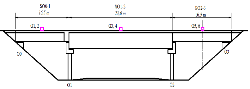
Figure 7 The arrangement of geophones on reinforced concrete spans of a railway overpass: SO0-1, SO1-2, SO2-3 - spans of an overpass. G1, G2, G3, G4, G5, G6 geophones “EP-300 compakt”; О1, О2 - frame, two-rack intermediate supports; О0, О3 - abutments of bulk type
Tests of this overpass were carried out on April 18, 2018 in the daytime, at an outside temperature of +18°C. As an example, graphs of the spectral density of reinforced concrete spans 16.5 m (Figs. 8-9), and 23.6 m (Figs. 10-11) are presented when the “locomotive + wagon” coupler descends from the overpass passing at a speed of 50 km/h.
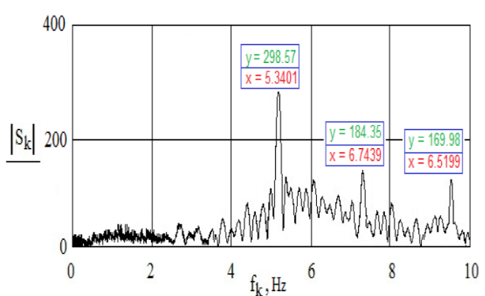
Figure 8 The range of horizontal movements of the middle section of a reinforced concrete beam 16.5 m (transverse bending modes of vibration).
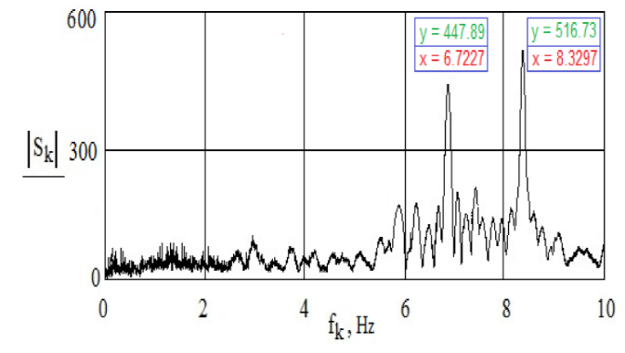
Figure 9 The range of vertical displacements of the middle of a reinforced concrete beam 16.5 m (vertical bending modes of vibration).
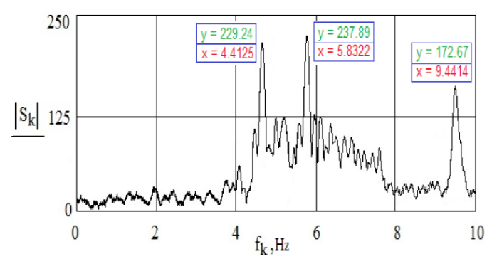
Figure 10 The range of horizontal movements of the middle section of a reinforced concrete beam 23.6 m (transverse bending modes of vibration).
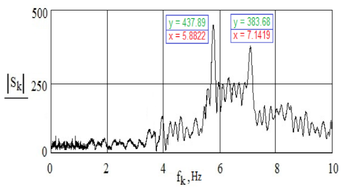
Figure 11 The range of vertical displacements of the middle section of a reinforced concrete beam 23.6 m (vertical bending modes of vibration).
The data obtained during the testing of beam spans of a railway overpass after a mobile load has collapsed (“locomotive + wagon” coupler), shape (mode) and natural vibration frequency are summarized in Table 2.
Table 2 Frequencies of natural vibrations of overpass spans.
| Overpass at km 56 PK9 + 50 of the Kulsary-Tengiz railway line | ||||
| Mode (Form) | 1st. | 2nd. | 3rd. | |
| Span: reinforced concrete beam 23.6 m | ||||
| Transverse frequency, Hz | 4.41 | 5.83 | 9.44 | |
| Vertical frequency, Hz | 5.88 | 7.14 | - | |
| Span: reinforced concrete beam 16.5 m | ||||
| Transverse frequency, Hz | 5.34 | 6.74 | 9.52 | |
| Vertical frequency, Hz | 6.72 | 8.33 | - | |
As a result of the analysis of the tests, it was determined that the effect of the rolling stock passing through the reinforced concrete beam spans of 16.5 m and 23.6 m appears with frequency perturbations that are in the range f = 4.41 ÷ 9.52 Hz.
These disturbances primarily determine the reaction of spans. Perturbations whose frequencies do not fall into these regions, as follows from the analysis of the spectra, do not play a special role in shaping the behavior of spans, since their amplitudes are very small and the energy, they introduce into the system is negligible. An analysis of the experimental data characterizing the operation of the overpass made it possible to establish the parameters of free vibrations of unloaded spans.
4. Conclusions
From the analysis of the calculated and experimental values of the vibrations of the beam reinforced concrete spans of the overpass using the fast Fourier transform as a signal processing tool, it follows that to determine the period of the natural vibrations of the span for comparison with the normalized range, you can apply the effect on the structure that has come down to a moving load.
The obtained forms (modes) of frequencies (periods) of natural vibrations correspond to the lowest vibration form of spans, the values of which can be used in calculations of such artificial structures for earthquake resistance, as well as in dynamic stability calculations for prospective loads. In order to determine the actual technical state of structures and the most effective assessment of the reliability of bridge structures and establish correspondence between the design scheme and the actual operation of structures on the trunk lines of Russia and Kazakhstan, it is necessary to periodically monitor the stress-strain state of structures under operational loads.

