


![Retraction notice to "Buyer-Supplier Transport Access Measures for Industry Clusters" [JART 12 (2014) 839-849]](/img/en/next.gif)


 text new page (beta)
 English (pdf)
 Article in xml format
 Article references
 Send this article by e-mail
 Cited by SciELO
  Similars in
SciELO
Similars in
SciELO 
 Permalink
1. Introduction
A lot of progress has been made on the ability to produce long lengths of strong optical fibers for telecommunication networks. Thereby, some important advances have also been made in the protection of the external surface of the fiber from environment damage through the development of new coatings. Among these coatings, epoxy acrylate coatings were used in telecommunication networks; during the drawing, the application of the polymer on the fiber was easy and its polymerization was very fast. However, there is not a sufficiently detailed understanding of the influence of aging conditions on the fiber strength when these types of fibers were aged in an aqueous environment and under mechanical stress (Evanno, 1999; Gougeon, 2003). It is important to estimate the life duration of these fibers generally degraded under moisture and mechanical torsion stresses when these ones must be used in harsh environments.
Shiue and Matthewson (2002) have studied the effect of the temperature variation of water pH on the static fatigue of fused silica optical fibers and its impact on the apparent activation energy.
Sakaguchi and Hibino (1984) were interested by the fatigue in the low-strength of silica optical fibers. The fatigue behavior is mainly characterized by crack growth parameter n (stress corrosion parameter). The value of n for low-strength fibers which contain macroscopic flaws has not been sufficiently clarified, because only a few examinations have been made on low strength fibers (Donaghy & Nicol, 1983; Gulati, Helfinstine, Justice, McCartney, & Runyan, 1979), although many studies have been made on high-strength fibers which have no macroscopic flaws (Chandan & Kalish, 1982; Kalish & Tariyal, 1978; Sakaguchi & Kimura, 1981). The allowable loading condition needed to prevent any growth of the macroscopic flaw was discussed in order to assure high reliability for the fiber.
Chen and Chang (2002) have focused on the fracture mechanics of silica optical fibers to evaluate the strength and fracture characteristics of single and multi-mode fibers subjected to uniaxial tensile testing and two-point bending. The fracture strength data of both single and multi-mode under either testing were found to be very similar. The fracture stresses at 50% fracture probability for tensile testing and two-point bending were 4.5 and 5.1 GPa, respectively. The fracture characteristics of each tested optical fiber specimen were evaluated by using an SEM. A critical flaw on the surface of glass fiber was found to be the fracture origin for specimens under either tension or bending as expected.
Besides signal transmission for telecommunications, fibers are used in an increasing number of devices. A number of applications relate to devices exposed to severe wet environment (hot water, chemical attacks, etc.). It is the case for the sensors used in nuclear plants, high energy physics or plasmas devices.
Reliability issues must be addressed for optical fiber sensors operating under severe conditions such as harsh chemical solutions.
El Abdi, Rujinski, Poulain, and Severin (2010) have studied the mechanical behavior and aging of fibers exposed to hot water action, to hydrofluoric acid vapors (HF) and to tetramethoxysilane (TMOS) for different durations. Standard fibers tested immediately after exposure show a broader distribution of fiber strength accompanied by the drastic decrease of the failure stress. Polymer reacts with different wet environments, which induces viscosity changes.
Fiber-optic sensors are also mostly used for in situ measurements of diverse chemical composition of industrial surfactants employed in industry as detergents, emulsifying and dispersing agents, coatings, and pharmaceutical adjuvants. Another work (El Abdi, Rujinski, & Poulain, 2015) was undertaken to study the mechanical behavior of optical fibers in contact with Cetyl Trimethyl Ammonium Chloride (cationic surfactant used as a very toxic antiseptic) in aqueous solution (CTAC) at different immersion durations and different temperatures. Result analysis demonstrates that immersion in CTAC drastically decreases the fiber strength particularly when immersed for long aging periods at high temperatures.
In our study, the used fibers were among the last qualified fibers and used in telecommunication networks. They contain very high quality silica and have an improved polymer coating.
In this work, the mechanical strength of a silica optical fiber aged in distilled water at different temperatures was studied. Optical fibers were then wound around alumina mandrels with different diameters in order to evaluate the influence of the static bending stresses on the lifetime of the fiber.
The results should be used to determine the fatigue fiber parameter changes (activation energy, stress corrosion parameter, fiber lifetime) according to water temperature (from 20 °C to 70 °C) and applied bending stresses to give a lifetime modeling of optical fibers in static fatigue.
2. Experimental
2.1. Optical fiber used
The used monomode fiber has two acrylate coatings (primary and outer coatings).
This fiber was manufactured using the Outside Vapor Deposition (OVD) process which produces a totally synthetic, ultra-pure fiber. It has high strength and low attenuation. Its dual acrylate layer (CPC6) coating provides excellent fiber protection. On the other hand, the operating temperature range was −60 °C to +70 °C. A soft, primary coating has a low module of elasticity, adheres closely to the glass fiber and forms a stable interface. It protects the fragile glass fiber against micro-bending and attenuation. The outer coating protects the primary coating against mechanical damage and acts as a barrier to lateral forces. It has a high glass temperature and Young modulus and a good chemical resistance. The combined coating diameter is 245 μm ± 5 μm, the clad diameter is 125 μm ± 1 μm and the coating thickness is equal to 62.5 μm ± 2 μm.
2.2. Test bench used
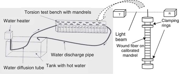
Optical fiber was wound onto an alumina mandrel of 2.6, 2.7, 2.8 or 3 mm in diameter (Fig. 1). Electrical engine helps to wound fibers around alumina mandrels. A counter gives the maximum number of circumferences around each mandrel. The winding of each fiber was automated and the same applied stress was obtained for each fiber. The real deformation for each fiber depends on the mandrel diameter; with the use of suspended mass (Fig. 1) each fiber has taken on the exact shape of the mandrel.

The extremities were clamped in two oblique cuts simple clamping rings, made of elastomer-rubber, and mounted on the extremities of the alumina mandrels. Once the fiber was wound around the mandrel, it was placed between a transmitter T and a light receiver R (Fig. 2). The light beam cannot reach the receiver and from then on the time of fiber loading is triggered. The mean time to failure is recorded, and this corresponds to the time required for the fiber strength to degrade until it equals the stress applied through winding round the mandrel. The time to failure is measured by optical detection when the ceramic mandrel moves out of the special holder. When fiber breaks, the mandrel rocks from its vertical static position, the light beam can reach the receiver and the time to failure is directly recorded with an accuracy of ±1 s. The testing setup consists of a large number of vats containing 16 holders each.
The alumina mandrels have a very low surface roughness. The friction between the fiber polymer coatings and the mandrel is negligible.
For fiber aging in hot water, we developed a water circulation system (Fig. 2). The system comprises a 9 l plastic tank in which is immersed a water heater with a resistance heater and a discharge pump. A water diffusion tube sends water at the desired temperature to the testing bench with mandrels. Thus the fibers (wound around a mandrel) can be aged in water at different temperatures.
2.3. Theoretical relation used
The stress-strain relation of optical fibers was first examined by Mallinder and Proctor (1964). They found that the applied stress σ (GPa) for an optical fiber is related nonlinearly to the strain ɛ (where both σ and ɛ are positive in the tensile region), according to:).
 (1)
(1)
where E 0 is the Young modulus (=72 GPa for the silica); α' = 0.75α and a value for the non-linearity constant α of 6 can be used (Glaesemann, Gulati, & Helfinstine, 1988
One can note that a wound fiber was subjected to compressive stresses on its internal part (fiber surface close to the curvature center) and a tensile stress on its external part (fiber surface furthest away from the curvature center).
A tensile stress is experienced by the outer surface of the fiber. The bending stress must first be calculated from the mandrel diameter ϕ. This can be performed with (1) and the simple expression for the maximum strain ɛ (Griffioen, 1994):
 (2)
(2)
ϕ is the mandrel diameter (in μm); d glace , is the glass fiber diameter (=125 μm); d fiber is the fiber diameter (=245 μm), including the layer polymer coating. This leads, in the case of a usual fiber, to the corresponding stresses of 3.22 GPa for the calibrated diameter mandrel of 2.8 mm.
2.4. Boundary test conditions
As has been documented it was known (El Abdi, Rujinski, Borda, Severin, & Poulain, 2008; El Abdi et al., 2010; El Abdi et al., 2015; Gougeon, Sangleboeuf, El Abdi, Poulain, & Borda, 2005), the fiber coating begins to be damaged above 80 °C. It changes color and its odor was released. The chemical environment of the silica surface was modified and the fiber core damage was accelerated.
The results obtained at very high temperatures (higher than 80 °C) cannot be used to predict the behavior of the fiber at lower temperatures. For our tests, a maximum temperature of 70 °C was used so that the polymer coating would not suffer temperature damage.
3. Results and discussion
3.1. Influence of aging environments
The polymer coating was permeable. Thus, when a fiber was put in water, a significant number of water molecules diffused into the interface between the coating and the fiber core and the rate of reaction between the H2O molecules and the Si-O glass network was determined by the temperature.
Fibers were wound on mandrels and aged in air and distilled water at 20 °C (Fig. 3).

Thus, upon application of a stress, the fiber damage was much higher in water than in the air (time to failure ratio was about 10). The number of water molecules activated here was considerably higher than those in air.
3.2. Temperature dependence of failure time
The different diameters of the alumina mandrels (2.6, 2.7, 2.8 and 3 mm) produced stress values of 3.47, 3.34, 3.22 and 3.01 GPa respectively. For each temperature T (20, 30, 40, 50, 60 and 70 °C) and for each diameter, 16 mandrels were used each with 1 m wound optical fiber.
The averages of times to failure according to temperature and applied stress are given in Figure 4. For each value, the standard deviation was about 10% (the average value is obtained from 16 measured samples).

Figure 4 shows that whatever the stress level may be the logarithm of the time to failure tf, increases linearly with respect to the inverse of temperature. Thus, we can write:
 (3)
(3)
 (4)
(4)
The fatigue of a silica optical fiber was controlled by the crack growth rate c., which depends on the reaction rate between water and silica. On the other hand, Wiederhorn and Bolz (1970) developed a chemical kinetic model for the crack growth, based on simple chemical kinetics in which the stress at the crack tip modifies the effective activation energy for the bond rupture via an activation volume (Shiue & Matthewson, 2002):
 (5)
(5)
where Q is the apparent activation energy and R is the perfect gas constant (R = 8.314 J mol−1 K−1).
Wiederhorn and Bolz (1970) found that Eq. (5) fits the crack velocity data of various studied glasses. From Eq. (5), the time to failure of the material tf, which inherits the temperature dependence of .c , is therefore inverse Arrhenius (Matthewson & Kurkjian, 1988):
 (6)
(6)
The experimental results have enabled us to determine the values of Q and C for different stress levels. These parameters are summarized in Table 1. According to applied stress, the strain slowly decreases but remains around 4%. The activation energy Q tended to increase when the applied stress decreases. Indeed, for a decrease in stress from 3.47 to 3.01 GPa, the Q parameter increased from 55 to 75 kJ/mol (Fig. 5).
Table 1 Q and C values versus applied stresses.
| Mandrel diameter (mm) | Applied stress (GPa) | Deformation, ɛ (%) | Q (kJ/mol) | C (h) |
|---|---|---|---|---|
| 2.6 | 3.47 | 4.38 | 55.2 | 9.5 × 10⁻¹⁰ |
| 2.7 | 3.34 | 4.24 | 61.3 | 2.5 × 10⁻¹⁰ |
| 2.8 | 3.22 | 4.10 | 65.4 | 10−10 |
| 3 | 3.01 | 3.85 | 75.4 | 1.2 × 10⁻¹¹ |

On the other hand, for a static fatigue test carried out on a silica fiber, Kao (1980) observed an increase of Q from 45 to 55 kJ/mol. when the applied stress decreases from 3.4 to 2.9 GPa. Similarly, Duncan, France, and Craig (1985) obtained an activation energy of 50 kJ/mol, with dynamic tests.
The values of Q obtained by Kao and Duncan are slightly different from the ones we measured, because the coating materials in the two studies are different and so the coating/silica interface were be exposed to different ionic environments.
In the case of dynamic tests, the deformation can play a major role and the activation energy can change with stress level (Inniss, Kurkjian, & Brownlow, 1992). Kao was the first to demonstrate that the activation energy of lightguide fibers is stress-dependent (Kao, 1980). While Chandan and Kalish (1982) report temperature dependent fatigue data, they are treated with the power law, as are the temperature-dependent data of Krause and Shute (1988). Ritter, Glaesemann, and Jakus (1984) used an exponential law to fit temperature-dependent dynamic fatigue data, and the predicted curves are used to construct the stress-dependent activation energies.
As indicated in Figure 6, the C logarithm increases linearly according to the applied stress σ . thus, one can write:
 (7)
(7)

Shiue and Matthewson (2002) show that the activation energy Q can be expressed as:
 (8)
(8)
where Q* is the apparent activation energy under zero stress, and the term (β·σ) represents the stress effect on the apparent activation energy.
If γ is equal to R ·C 2 (=75 SI), Eq. (6) can be expressed as:
 (9)
(9)
Eq. (7) can be written as:
 (10)
(10)
Using Table 1 and a linear regression, one can deduces the C 1 and C 2 values (equal to 2.3 × 10⁻²³ and 9.34 respectively), β and Q* values (equal to 43.4 kJ/(GPa mol) and 205 (kJ/mol) respectively). So, a complete identification of the time to failure model is obtained.
The term (γ ·T·σ ) has a physical meaning which is a little more complex. When the fiber was subjected to stresses, the Si-O links in the glass network were set in motion to achieve the equilibrium position corresponding to this new state of stress.
This movement is known as the structural relaxation . At room temperature, the relaxation is very slow, but at higher temperatures the atoms and molecule motions were much faster and the relaxation occurs more rapidly.
Thus, (γ ·T·σ ) characterizes the influence of the relaxation on the time to failure for a fiber.
3.3. Change of failure with applied stresses
Figure 7 gives the fatigue curves for different aging temperatures between 20 °C and 70 °C.

One can note that whatever the temperature, the fatigue curve can be described by a straight line.
Concerning aging in water, many authors have shown (Chandan & Kalish, 1982; Cuellar, Roberts, & Middleman, 1987; Krause, 1979; Wang & Zupko, 1978) that the fatigue curve is not linear over the stress range. From a certain stress level, the fatigue curves present a slope change and therefore a change for the n parameter. This transition in the slope is known as the "knee" phenomenon.
In the case of a standard fiber aged in water at 85 °C, Cuellar, Kennedy, Roberts, and Ritter (1992) observed a change in the slope for a stress of about 2.7 GPa. The time to failure occurs at 12 days.
This slope change results from coating damage in hot water. The coating damage occurs more rapidly if the water temperature is high.
As we previously stated, all fatigue tests were carried out on a fiber with a new kind of coating. It has been shown (Kuyt, Leclercq, & Breuls, 1995) that this new kind of coating has a good resistance to temperature and to water. It is therefore a very good protection for the fiber when used in harsh environments. All aging tests were conducted at a maximum temperature of 70 °C and the coating does not undergo significant damage after relatively long aging durations.
We can therefore assume that when the water temperature does not exceed 70 °C, the coating does not undergo significant damage during the aging duration. The "knee" phenomenon doesn't occur and the n parameter remains constant during the used stress range.
3.4. Change of the stress corrosion parameter according to temperature
Eq. (9) gives the time to failure versus applied stress, temperature and activation energy. The time to failure can also be obtained as a function of stress corrosion parameter, mechanical and geometrical material parameters and applied stress for a material with the presence of a microcrack.
The subcritical crack growth model which assumes the presence of well-defined sharp surface crack which locally amplify the applied stress at the crack tip is related to the stress intensity factor, K I , for a crack of length c subjected to a remotely applied stress σ by the following relation:
 (11)
(11)
where Y is a parameter of order unity which describe the crack shape shape (=1.24 for a halfpenny shaped crack existing on the fiber surface), K I is a measure of the intensity of the stress field at the crack tip and when it exceeds a critical value, K IC , the intrinsic strength of the material is exceeded and catastrophic failure occurs. The combined influence of stress at the crack tip and reactive species in the environment (particularly water) leads the strain in the bonds at the crack tip to reduce the activation energy for the chemical reaction between water and the silica so that silicon-oxygen bonds are slowly broken, progressively advancing the crack (Wiederhorn, 1972). A power law relationship between the crack growth rate c. and the applied stress intensity at the crack tip is assumed:
 (12)
(12)
A is a parameter which is environment dependent and n is the stress corrosion parameter which refers to the crack growth parameter.
Therefore, the applied stress causes the crack to extend, which itself increases K I , leading to an increases in the growth rate. In most reliability models, the applied stress is assumed to be static (σ constant) so that the tie to failure, t f , is given by (Evans & Wiederhorn, 1974):
 (13)
(13)
where S i is the middle value of the initial intrinsic strength of the material (GPa).
Tiffany and Masters (1964), Wiederhorn (1973) and Tetelman (1972) give the time to failure according to initial intrinsic fiber strength and applied stress as follow:
 (14)
(14)
where B is equal to
 (15)
(15)
Eq. (14) can be expressed as:
 (16)
(16)
The use of Eq. (16) gives the stress corrosion parameter n versus t f and thus versus temperature.
The n values were determined through experimental results given in Figure 7 and the use of Eq. (16). The n parameter decreased with temperature (Fig. 8). This parameter was proportional to the inverse temperature (1/T ) and a straight line passes through all the experimental values.

The n parameter can be expressed as: where a 0 = 15,180 K and b 0 = −28.
 (17)
(17)
Eq. (17) gives a good approximation for n according to temperature. A high stress corrosion parameter n involves a significant slope for the curve of the time to failure and therefore great fiber sensitivity to applied stresses.
This equation was also observed by Sakaguchi and Hibino (1984) during a dynamic test carried out on a sample of solid silica glass for a temperature range from 20 °C to 80 °C.
By examination of previous work on silica glass both with and without damage, one may postulate four distinct regimes which, without any other information, would be expected a priori to have four distinct applicable micromechanics models (Matthewson, 1993). One can note that four types of defects expected to be encountered in silica:
Pristine defect (any defects are of atomic dimension) for n ∼ 20 which is a surface phenomenon,
Subthreshold type defect (i.e. without well-defined cracks) for 10 < n < 20 where the crack initiation is dominated by residual stresses,
Postthreshold type defect (i.e. with well-defined cracks) for n ∼ 30 where crack propagation is dominated by residual stresses,
Macroscopic crack for n ∼ 40 with sharp and residual stress free cracks.
Eq. (17) forms the basis of the most reliability models since it relates the expected life of the material to the applied stress and starting strength (Matthewson, 1993); or conversely it specifies the maximum permitted service stress for a given service life. This equation is sensitive to the value of the stress corrosion parameter, n , which it is typically around 20 or more for silica fibers.
Figure 8 shows that the n parameter was between 16 and 26 according to temperature and leads to conclude that the crack initiation was dominated by residual stresses.
3.5. Fatigue curve for different temperatures
If one makes an extrapolation to high stress values of the experimental results given in Figure 7, one obtains the schematic representation shown in Figure 9.

Figure 9 shows that for a very particular stress value, denoted σ E , the different static fatigue curves meet each other. When the applied stress becomes greater than σ E , the temperature has an opposite effect and a low temperature led to a low time to failure.
The stress σ E has a much higher value than the stresses commonly used. Thus, under σ E , the time to failure t fE was well below the times to failure measured during experimental tests.
In our tests, for an aging temperature of 70 °C and for a stress equal to 3.47 GPa, the time to failure remained at less than half an hour. This implies that for a stress higher or equal to σ E , the time to failure would be extremely small. Kurkjian (1989) has pointed out that this would correspond to time to failure on the order of a few microseconds. From a practical point of view, the use of this high stress would be unrealistic because it would lead to an instantaneous failure of the fiber. For industrial uses, the minimum value of the applied stress must be optimized. The fiber must not support a low stress (so that the mechanical properties of the fiber can be used) and not a high stress to avoid premature failure of the fiber.
4. Conclusions
The change of the time of rupture of the fiber as a function of the temperature and the applied stress level was studied. The results obtained have provided a measure of the fatigue parameters of the fiber according to the water temperature.
The time to failure was dependent on applied stress and also on water temperature. It decreased when the temperature or the stress increased. But when the applied stress became greater than σ E , the temperature led to an increase in fiber strength.
The temperature induces two opposite effects: it stimulated the reaction between water and the Si-O bonds of the vitreous matrix and secondly it contributed to moving the system to its equilibrium position against the applied stress. The first effect was predominant and gave a decrease of time to failure when the temperature increased.
The n parameter was sensitive to temperature. It characterized the sensitivity of the fiber to applied stress, and decreased linearly according temperature. Thus, the fiber became less susceptible to applied stresses with increasing temperature.
Finally, the activation energy Q was a decreasing function depending on the applied stress.

