SciELO - Scientific Electronic Library Online

 
vol.63 issue1Simple harmonic oscillator with fractional electric potentialAn estimation method of fractal dimension of self-avoiding roughened interfaces author indexsubject indexsearch form
Home Pagealphabetic serial listing  

Services on Demand

Journal

Article

Indicators

Related links

  • Have no similar articlesSimilars in SciELO

Share


Revista mexicana de física

Print version ISSN 0035-001X

Rev. mex. fis. vol.63 n.1 México Jan./Feb. 2017


Research

Synthesis and characterization of Co-doped Lanthanum Nickelate perovskites for solid oxide fuel cell cathode material

L. Chávez-Guerreroa  b  * 

M. Hinojosa-Riveraa 

B. Medina-Lottc 

R-N. Vannierd 

A. Ringuedéc 

M. Cassirc 

aUniversidad Autónoma de Nuevo León, Cd. Universitaria, San Nicolás de los Garza, México, 66450, México.

bCentro de Innovación, Investigación y Desarrollo en Ingeniería y Tecnología, Avenida Alianza 101 Sur KM. 10 de la nueva carretera internacional de Monterrey, Apodaca, Nuevo León-México, 66600, México.

cInstitut de Recherche de Chimie Paris, CNRS-Chimie ParisTech, 11 rue Pierre et Marie Curie, 75005 Paris, France

dUnité de Catalyse et de Chimie du Solide, UMR 8181 CNRS, Villeneuve d’Ascq, France.


Abstract

In the perovskite structures widely investigated and used as Solid Oxide Fuel Cells (SOFC) cathodes, oxygen reduction is mainly limited to the triple phase boundary (TPB), where oxygen (air), electrode and electrolyte are in contact. It is possible via the sol-gel modified Pechini method to: 1) control the material grain size, which can increase TPBs, 2) produce a homogenous material and 3) obtain a cathode material in a faster way compared with the solid state route. LaNi x ,Co 1-x O3 (x=0.3, 0.5, 0.7) were synthesized by the modified Pechini method. The perovskite phase formation began at 350°C and the presence of pure LaNi0.7Co0.3O3 LaNi0.5Co0.5O3 and LaNi0.3Co0.7O3 structures was evidenced by High Temperature X-ray diffraction (HT-XRD) measurements. Scanning Electron Microscopy (SEM) micrographs showed that the microstructure evolves with the amount of cobalt from a coalesced to an open structure. Electrochemical impedance spectroscopy (EIS) on symmetrical cells LaNi x Co 1-x O3/YSZ (yttria-stabilized zirconia)/LaNi x Co 1-x O3 showed that the highest ASR (area specific resistance) is obtained with x = 0.3, whereas ASR values are similar for x = 0.5 and 0.7 at temperatures higher than 600°C. At temperatures lower than 600°C, ASR is the lowest for LaNi0.5Co0.5O3, showing that this composition with intermediate porosity appears as a good choice for an intermediate-temperature solid oxide fuel cell (SOFC).

Keywords: Wet chemistry; SOFC cathode; Co content; microstructure; area-specific resistance

PACS: 88.30.M-; 88.30.pn

1. Introduction

Solid Oxide Fuel Cells (SOFCs) have the potential to become a clean profitable power generating technology in the near future, as they display a high energy conversion efficiency and possible cogenerating and internal reforming properties. Materials for SOFCs are constituted of five key stack components, which are the anode, electrolyte, cathode, interconnectors and seals1,2. While good performances are obtained with the classical anode constituted by YSZ-Ni cermet, performance of the cathode still has to be improved1. In order to optimize this, the cathode must have a high mixed ionic-electronic conductivity under an oxidizing atmosphere, a good chemical compatibility, a thermal expansion coefficient similar to that of the electrolyte, enough porosity to allow gaseous oxygen diffusion through the cathode and the cathode/electrolyte interface, a stable structure during manipulation and operation under an oxidizing atmosphere and high catalytic activity3,4.

A perovskite-type oxide follows the formula ABO3, where cations such as La, Sr, Ca and Ba represent the A-site and Cr, Mn, Ni, Fe and Co occupy the B lattice site for most of the materials used as cathodes. While Sr-doping at the A-site in perovskite materials enhances the ionic conductivity, Co doping on the B-site increases the electronic conductivity1.

One of the most commonly used materials for high temperature (800-1000°C) SOFCs is a composite of manganite-based La1-xSrxMnO3±δ (LSM) and yttria-stabilized zirconia (YSZ)5. In addition to electrical properties, the microstructure design plays a crucial role in the cathode performance 2; the main objective when the material is synthesized is to minimize the ohmic loss by increasing TPBs. In general, it is preferable to have SOFCs operating at an intermediate temperature (500-700°C), which is only possible when sufficient ionic conductivity in the electrolyte is achieved2.

The perovskite-type LaNiO3, exhibits a high electronic conductivity at room temperature but is unstable above 850°C. Its performance has been improved by doping it with cobalt. Chiba et al. 6, in a set of experiments with LaNiMO3 [M = Al, Fe, Ga, Cr, Mn, Co], found that cobalt promotes the highest conductivity at 812°C, just followed by iron, while the rest of the elements produced conductivity values of up to two orders of magnitude lower. Cobalt doping has been also reported to improve catalytic reactions, since it alters the electronic structure of perovskites 7.

A decrease in the working temperature of the cells would lead to cost reduction and increase of the materials lifetime4,5,6, but it supposes to find new cathode materials with improved kinetics towards oxygen reduction. In this sense, new compositions and structures of perovskite materials are still promising.

Several methods are used to prepare perovskite materials, some using the solid state route, such as mechanical milling5 and calcination of powders in air 6, or by wet chemistry such as spray-freeze-drying 8, surfactants9, Pechini10, sol-gel11, reverse micelle12, nitrate molten salts13, flash microwave14 and polymerization15. The perovskite lattice can tolerate multiple cation substitution with slight changes, which means that many properties can be modified by obtaining the desired material without provoking significant distortion. The modified Pechini method has several important advantages: homogeneity easily achieved, well-controlled morphology, sub-micrometrical particles and specific composition achieved because the mixing of species occurs at the atomic scale.

2. Experimental

In the present work, LaNi x Co 1-x O3 (x = 0.3, 0.5, 0.7) perovskite ceramic, synthesized by sol-gel modified Pechini method, as a cathode material for SOFCs operating at intermediate temperatures were investigated. In addition, the influence of the cobalt amount on electronic conductivity and the densification of the produced material, plus the reactivity of the mixture cathode/electrolyte, were explored. Additionally, suspensions were formulated into an azeotropic mixture of methylethylketone (MEK) and ethanol (ETOH), two additives such as PVB binder and phthalate plasticizer were used, with Zetasperse 2300 as a dispersant. An YSZ substrate was dip-coated on both sides with LaNi x Co 1-x O3 in order to produce a symmetrical cell in order to determine ASR values in a temperature range from 450 to 750°C.

Three compositions of LaNi x Co 1-x O3 (x: 0.3; 0.5 and 0.7) were synthesized via a polymeric route. This method follows a procedure similar to that reported by Pechini9. Reagent grade metal nitrates of La(NO3)3 6H2O, Ni(NO3)3 6H2O and Co(NO3)26H2O were mixed and dissolved in deionized water. Chelating and polymeric agents such as hexamethylenetetramine (HMTA), acetylacetone (Acac) and acetic acid were mixed in the appropriate molar ratio with the cations to obtain the solution. The ratio of HMTA to metal ions was 3 while the HMTA/Acac ratio was 1:1. The resulting solution was maintained at 65°C for 10 min under constant magnetic stirring. A mix was formed and then heat-treated at 300°C for 1 h, resulting in precursory amorphous powders. These materials were calcined at 1000°C for 5 h at a heating rate of 5°C/min. LNC37, LNC55 and LNC73 were used as labels for LaNi0.3Co2.7O3, LaNi0.5Co0.5O3 and LaNi0.7Co0.3O3 respectively. Amorphous precursors were characterized by high temperature X-ray diffraction (HT-XRD) on a Bruker D8 advanced diffractometer, equipped with an Anton Paar HTK 1200 N high temperature chamber and a Vantec rapid detector (Cu K α radiation, λ=1.54 Å). Experiments were carried out from room temperature to 1000°C in the 10-80° 2 θ domain with a 0.0148 step and a counting time of 0.2 sec per step (each pattern was collected in 16 min 5 sec) under air flow (5L/h) with a 0.1°C/s heating rate between each diffractogram. Powders were deposited on a piece of platinum foil to avoid any reaction with the sample holder made of alumina. A PANalytical X’Pert PRO powder diffractometer was used for room temperature characterization with a 2 θ configuration (Cu K α radiation, λ=0.15406 nm, 10-90° 2 θ domain, 0.02° increment and acquisition time = 2.0 s). All the data were analyzed using the profile matched in the software database. SEM images of Au-coated samples were obtained using a SEM-FEG with an EDX model LEICA S440 scanning electron microscope. Commercial powder material 8YSZ (TOSOH-TZ-8YS) was used to elaborate a substrate in order to coat each cathode composition on it. The raw substrates were pressed at 4 Tons and their dimensions were an average of 13 mm (diameter) × 2 mm (thickness). After this, the raw substrates were sintered at 1400°C for 1 hour at a heating rate of 5°C/min. In order to coat each compound on the YSZ substrate, three suspensions were prepared with LNC37, LNC55 and LNC73 powders and those were diffused into an azeotropic mixture (MEK/ETOH) with the additives in similar amounts to the ones presented by Castillo et al. 16, using t Zetasperse 2300 dispersant instead of C213. One layer of each compound was deposited by dip-coating on each side of an YSZ substrate, which was immersed into the suspension and then withdrawn at a controlled speed (3 cm/min). A heat treatment was employed to avoid cracks or pits in the perovskite coatings on the YSZ15. Symmetrical cells LNC37/YSZ/LNC37, LNC55/YSZ/LNC55 and LNC73/YSZ/LNC73 were assembled. Electrochemical impedance spectroscopy was performed using an Autolab spectrometer PGSTAT 30 with a 20 mV ac signal amplitude (ΔV) and no dc polarization for frequencies from 0.1 MHz to 20 MHz, with 11 points per decade.

3. Results and discussion

3.1 Phase analysis

According to the HT-XRD results (Fig. 1), an amorphous material was observed from room temperature to 350°C with crystallization starting above 350°C. Whereas peaks corresponding to the perovskite were evidenced from the beginning of crystallization for LNC37 and LNC55, an intermediate domain was observed for LNC73 with crystallization of the perovskite only above 525°C. The HT-XRD shows small peaks at 350°C corresponding to the residue, after the combustion of organics and nitrates, plus the formation of an intermediate phase of the perovskite. Thermogravimetric analysis was reported by Ivanova et al. 17, in the case of LaNi0.5Co0.5O3, where an intermediate product formed at 350-400°C, a spinel and a carbonate (La2O2CO3) were identified, which is in agreement with our HT-XRD results.

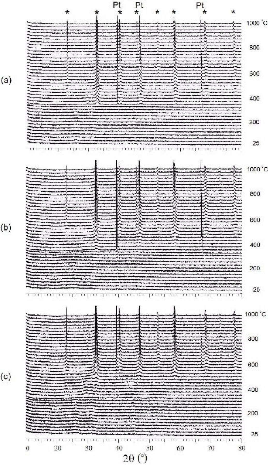
Figure 1. High-temperature XRD showing the crystallization profiles of the perovskite (*) in (a) LNC37, (b) LNC55 & (c) LNC73. 

Unit cell parameters were refined in an R 3¯c space group (Table I), in agreement with LaNiO3 and LaCoO3 perovskite cell without distortion18. The a-lattice parameter shows a systematic increase with the decrease of cobalt content in the LaNixCo 1-x O3 structure. The increase of the lattice parameter is likely due to a higher ionic radius, which is dependant of the mixed valences of nickel and cobalt.

Table 1. Perovskite unit cell parameters refined in R 3¯c on LaNixCo 1-x O3 powders. 

In all of the cases, the perovskite structure is obtained after 600°C, where a well-defined XRD peak can be identified around that temperature, after which the structure becomes crystalline, gradually forming the final structure at 1000°C. One advantage of this method is the time taken to reach crystallization, which is only 5 h or less to convert the amorphous powder into a full crystalline material. In comparison, solid state procedures require a longer amount of time at the same temperature to obtain the phase in a pure state or at least with enough order to be fully detected.

It can be inferred that the method may have influenced the structure and properties, as reported before for other materials15. In brief, it is well known that the cathode performance depends on its microstructural and morphological properties, for which reason these features must be well controlled and understood.

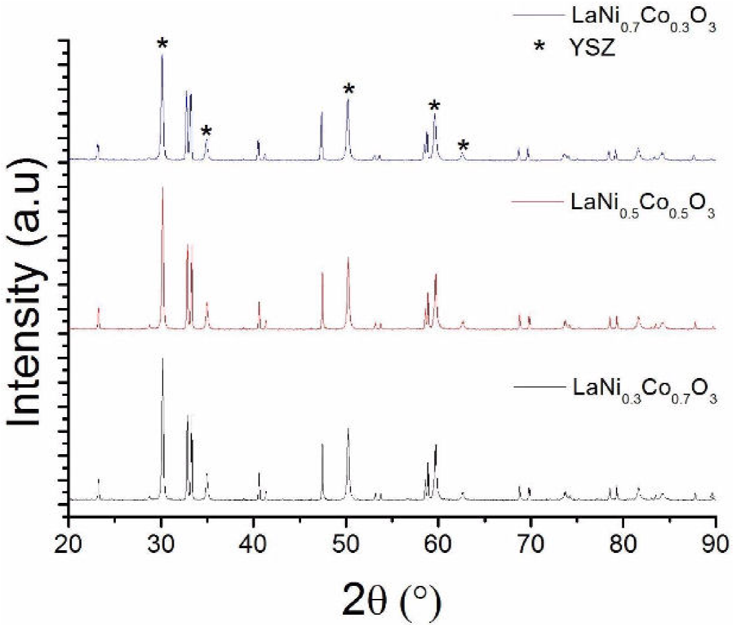
Preliminary stability tests were made by mixing the materials (LCN) with YSZ, then firing the mixture at 1000°C for 5 h, well above the typical SOFC working temperatures, which are around 700°C. For the three cathode materials, well-defined peaks corresponding to YSZ and the perovskite material can be observed in Fig. 2, where no impurity peaks are discerned in the spectrum, which suggests that no reaction appears at the interface and proves that these materials produced by the polymeric route have a good potential for SOFC cathodes. Of course, further studies are needed to judge on the feasibility of these new cathodes interacting with different electrolytes such as gadolinium doped ceria (GDC).

Figure 2. X-ray profiles showing the mixture of LaNixCo 1-x O3 and YSZ fired for 5 h at 1000°C. 

3.2 Morphology

Figure 3 show SEM micrographs of the calcined samples at 1000°C. In Fig. 3 (a-c), a mixture of YSZ and the cathode materials (50%/50% weight) are shown, while the pure perovskites are shown in Figs. 3 (d-f). Figure 3 (a-c) show fine particles 150 nm of YSZ and the larger grains of cathode material which can be distinguished by their different morphology. In Fig. 3(d), corresponding to LNC37, particles of 170-600 nm with a semispherical shape can be observed. In Fig. 3(e), round elongated shapes of LNC55 can been seen, the particles becoming larger and the interaction between them producing a denser structure. In Fig. 3(f), LNC73 a structure with a higher number of planar faces is observed; as the composition approaches the structure of the LaNiO3, the structure become more compact, exhibiting well connected sub-micrometric grains. With all these micrographs, it is possible to conclude that increasing the amount of cobalt promotes the increase of the porosity and the formation of rounded shape structures, which could be beneficial for free air flow passing through the material. Considering the three samples, it can be seen in Fig. 3(a-c) that the amount of YSZ interacting with the cathode is higher when the amount of cobalt increases (LNC37), because the YSZ particles can pass through the channels easily, increasing the TPBs, which is recommended in order to produce a good cathode material. No degradation can be observed, neither the change in composition nor the change in structure have been detected in the samples by either XRD or SEM.

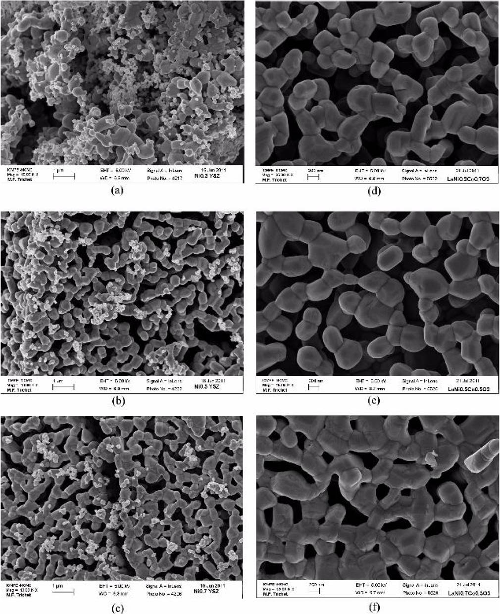
Figure 3. SEM micrographs showing the mixture of YSZ/LaNi x Co 1-x O3, where x = 3, 5, 7 in (a), (b) and (c) respectively and the crystallized LaNi x Co 1-x O3 material, where x = 3, 5, 7 in (d), (e) and (f) respectively 

Given that the electrochemical reaction can only occur at the triple-phase boundaries (TPBs), area is an important factor for reaction rate, therefore, it is more probable that LNC37 and LNC55 will be able to extend the TPB length, due to its open, less dense structure, thus enabling the contact between the perovskite, electrolyte and oxygen anions (O2-), improving the material properties and its feasibility as a new cathode for SOFC.

The particles shown in Fig. 3(d), with the highest proportion of Co, are more likely to be spherical in shape, having the smallest particle size (307 nm), while the smaller amount of Co produces significant faceting of the surface (grains) with a polygonal shape, creating a denser, more sintered structure with coarser grains (432 nm). Therefore, finer powders give rise to larger specific areas at the cathode/electrolyte interface and, consequently, a larger amount of triple phase boundary points.

LNC37 has the smallest grain size of 307 nm, in comparison with LNC55 showing a particle size of 416 nm, has a higher number of planar faces and appears to be in an intermediate stage of sintering. Even when the material is totally crystallized, the volume of the structure can be reduced by increasing the heating time at 1000°C, allowing the grains to grow through grain boundary diffusion. Further studies will be made using a full dense single phase material, which may have poor oxygen flow due to the lack of porosity, but with the probability of higher mechanical resistance. When conductive paths become clearer (LNC55 and LNC73), as the conductive particles are closer to each other, as shown in Fig. 3, then conductivity improves.

3.3 Area-specific resistance analysis

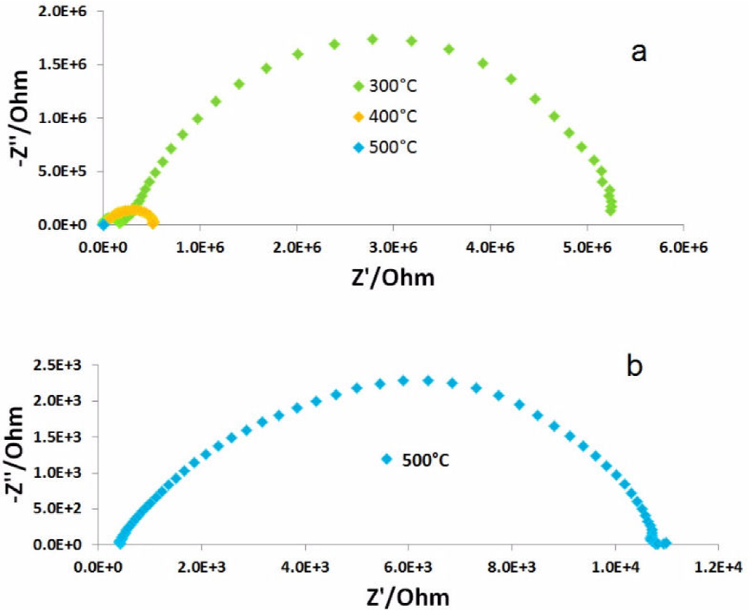
Area-specific resistance (ASR) as a function of temperature was obtained for each composition to determine the materials performance as electrode. All samples exhibit the same behavior, with resistivity decreasing with temperature, as shown in Fig. 4.

Figure 4. Area-Specific-Resistance (ASR) for each compound, indicating the Activation Energy (Ea). 

Intermediate work temperatures in the range of 800 to 500°C are considered, the ASR results at 762°C for the LNC73, LCN55 and LNC37 were 2.35 Ω cm2, 2.61 Ω cm2 and 4.53 Ω cm2, respectively. At this point, LNC73 had the best performance, and LNC37 showed the highest resistance. When the temperature is 625°C the resistance increases, this time the LNC73 resistance is 63.71 Ω cm2, while LNC55 keeps the lower value, 50.13 Ω cm2, showing an improvement as the temperature decrease. This is mainly because the activation energy (Ea) of the LNC55 is Ea = 0.68 eV, while LNC73 is Ea = 0.85 eV, then it is expected that the values will be lower, since the starting point for both samples was very similar. Electrical resistance activation energy is a barrier for conduction, the lower electrical resistance activation results in a higher conductivity. Thus, the intention is to decrease the work temperature of the SOFC, then at low temperature, less than 600°C, significant improvement was observed for the sample LNC55, which shows the lowest resistance at that temperature (102.07 Ω cm2) and the lowest Ea=0.16 eV, which means that even if the temperature continues decreasing, the rate of the resistance values will not increase as drastically as in LNC73 and LNC37. Note that for the three cases the slope changes at around 600°C, which implies changes in the activation energy and thus the rate limiting process. A similar behavior has been reported by Sayers et al19 for lanthanum nickelate and has been attributed to changes in electronic conductivity, which according to Daroukh et al20 has a maximum at around this temperature. It is clear that 600°C is the breaking point for all the samples, where the Ea is reduced but the resistance is too elevated after this point. For the LNC55 cathode, the improvement of its performance lies in the fact that there are more active sites for oxygen reduction reaction, because the electrochemical reactions can only occur at the TPBs. Figure 5 shows representative impedance diagrams, corresponding to LNC37 at 300°C, 400°C and 500°C confirming that as the temperature increases the impedance decreases. Note that, while we are reporting significant effects of cobalt doping based on concentrations, microstructural features and ASR measurements, along with impedance measurements, our results can also be associated to the fact that cobalt doping increases both mixed conductivity and catalytic activity of lanthanum nickelate.

Figure 5. (a) Impedance diagrams for LNC37 at different temperatures. (b) The curve for the 500±C test, amplified for more clarity. 

4. Conclusions

A cathode material with different compositions of LaNixCo 1-x O3 (x =0.3, 0.5, 0.7) was synthesized without phase contamination. The material crystallization began at 350°C according to high-temperature XRD which also confirmed the presence of pure compounds after sintering at 1000°C. The influence of composition on the structure was investigated; finding out that LNC55 has an open structure with rounded grains and is likely to have a better performance when used as a SOFC cathode, as shown by the ASR results. LNC55 has an intermediate structure showing the possibility of controlling the microstructure through the composition of the material, opening the possibility to design a material with the desired properties. According to our results, the importance and flexibility of the modified Pechini method is evidenced, and it can be used to design and produce cathode materials. The ASR performance of the materials in the range from 500 to 800°C for each compound showed that LNC55 got the lowest resistance (102.07 Ω cm2) at intermediate temperatures (578°C) and the lowest activation energy (Ea = 0.16 eV). When conductive paths become clearer (LNC55), as the conductive particles are closer to each other, as shown in Fig. 3, then conductivity improves. The electrical properties are also consistent with the morphologies shown in the SEM images.

Acknowledgments

This work was supported by the PROMEP, PAICyT, FIME-UANL and the Consejo Nacional de Ciencia y Tecnología (CONACyT) through the project 139278. Our gratitude to R.F. Cienfuegos for his technical support.

References

1. C. Sun, R. Hui, and J. Roller, J. Solid State Electrochem. 14 (2010) 1125. [ Links ]

2. S. Sunde, J. Electroceram. 5 (2000) 153. [ Links ]

3. A. Manthiram, J.H. Kim, Y.N. Kim, and K.T Lee, J. Electroceram. 27 (2011) 93. [ Links ]

4. H.C. Wang, Y.H. Lin, Y.N. Feng, and Y. Shen, J. Electroceram. 31 (2013) 271. [ Links ]

5. J. Chaichanawong et al., Adv. Powder Technol. 17 (2006) 613. [ Links ]

6. R. Chiba, F. Yoshimura, and Y. Sakurai, Solid State Ionics 124 (1999) 281. [ Links ]

7. H. Zhu, P. Zhang, and S. Dai, ACS Catalysis, 5 (2015) 6370-6385. [ Links ]

8. A. Tarancón, G. Dezanneau, J. Arbiol, and F. Peiró, J.R. Morante. J Power Sources 118 (2003) 256. [ Links ]

9. J.M. Serra and H.P. Buchkremer, J. Power Sources 172 (2007) 768. [ Links ]

10. M. Pechini, US Patent 330 (1967) 697. [ Links ]

11. Zongping Shao and Sossina M. Haile, Nature 431 (2004) 170. [ Links ]

12. M.A. Haider, A.J. Capizzi, M. Murayama, and S. McIntosh, Solid State Ionics, 196 (2011) 65. [ Links ]

13. P. Lenormand, M. Rieu, R.F. Cienfuegos, A. Julbe, S. Castillo, and F. Ansart, Surf. Coat. Technol. 203 (2008) 901. [ Links ]

14. L. Combemale, G. Caboche, and D. Stuerga, J. Solid State Chem. 182 (2009) 2829. [ Links ]

15. L. L. Conceição, C.R.B. Silva, N.F.P. Ribeiro and M.M.V.M. Souza, Mater. Charact. 60 (2009) 1417. [ Links ]

16. S. Castillo, R.F. Cienfuegos, M.L. Fontaine, P. Lenormand and P. Bacchin, F. Ansart. Mater. Res. Bull. 42 (2007) 2125. [ Links ]

17. S. Ivanova, A. Senyshyn, E. Zhecheva, K. Tenchev, R. Stoyanova and H. Fuess, J. Solid State Chem. 183 (2010) 940. [ Links ]

18. Chia Siang Cheng, Lan Zhang, Yu Jun Zhang and San Ping Jiang, Solid State Ionics 179 (2008) 282. [ Links ]

19. R. Sayers, M. Rieu, P. Lenormand, F. Ansart, J.A. Kilner and S.J. Skinner, Solid State Ionics 192 (2011) 531-534. [ Links ]

20. M. Al Darouch, V.V. Vashook, H. Ullmanna, F. Tietz and I. Arual Raj, Solid State Ionics 158 (2003) 141. [ Links ]

Received: July 28, 2015; Accepted: September 05, 2016

*Tel: 01(81)13404020. e-mail: leonardo.chavezgr@uanl.edu.mx

Creative Commons License This is an open-access article distributed under the terms of the Creative Commons Attribution License