


 nueva página del texto (beta)
 Inglés (pdf)
 Artículo en XML
 Referencias del artículo
 Enviar artículo por email
 Citado por SciELO
  Similares en
SciELO
Similares en
SciELO 
 Permalink
1.Introduction
Plasma acceleration occurs when a given current distribution carried by a plasma interacts with a magnetic field, either self-generated or external, producing a net electromagnetic force on the plasma that accelerates it in a particular direction. There are three well-known configurations of plasma accelerators in straight cylindrical geometry, known since last century: the z-pinch, the theta pinch and the plasma shock tube. In the z-pinch, the current flows in the axial direction, generates an azimuthal field and the force appears radially inward 1-5. In the theta pinch, an azimuthal current interacts with an externally generated axial magnetic field and again produces a radially inward force 6-8. For the plasma shock tube, also called coaxial plasma accelerators, a radial current flow generates an azimuthal magnetic field, and an axial force starts acting on the plasma 9,10. Coaxial plasma accelerators have many fields of applications as sources of high velocity shockwaves, as well as sources of high velocity, energetic and dense plasma 11. Such plasmas can be used to study the interaction between plasma and solids 11-13, including plasma-wall interaction in fusion reactor devices 14,15. Other applications of coaxial plasma accelerators include helicity injection in tokamaks 16, particle acceleration 17, plasma projection into vacuum and plasma propulsion
For all these applications, it is quite useful to have a model able to describe the plasma from its generation until it reaches the end of the acceleration system 9,10. The snowplow model 3 describes the dynamics of the current sheath and can be applied to a variety of devices. This model solves the coupled equations of the external equivalent circuit, the dynamic equations describing the plasma sheath motion, and the shock wave theory to compute the plasma temperature and the electron density.
2.Coaxial plasma accelerator
2.1.General description
The simplest configuration of a coaxial plasma accelerator consists of two coaxial conducting electrodes separated by an insulating region at the breech, and the space between them either pre-filled with gas or simultaneous gas puff injection and voltage triggering 21,22, as shown in Fig. 1 above. The outer electrode is a hollow cylinder, while the inner electrode may be either a solid or a hollow rod, and the insulator, either made of ceramic, glass or polymer 23,24 is usually a spacer or an integral part of the structure that holds the electrodes in place. The electrodes are connected to an external circuit, with one of the electrodes (typically the inner electrode) at high voltage while the other is grounded, causing electrical breakdown along the insulator surface, a process known as the breakdown phase. An electric current circulates along the ionized gas, forming a current sheath between the two electrodes 25.
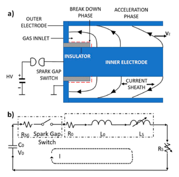
Figure 1 a) Schematic of a simple coaxial plasma accelerator, b) Equivalent RLC circuit for the coaxial plasma accelerator.
The electrical circuit of the system is shown in Fig. 1b). At t = 0, the spark gap switch is closed and the capacitor bank 𝐶 0 , charged with voltage V0 drains its charge into the circuit. A large electrical potential difference is established between the inner electrode, connected to the switch, and the grounded outer electrode (Fig. 1). The current flowing radially between the electrodes through a plasma sheath produces a magnetic field in the interelectrode region. The electromagnetic interaction between the current and its self-generated magnetic field produces a Lorentz force that is perpendicular to both the current density j and the magnetic field B vectors, given by j x B. If the current only has a radial component, the resultant force pushes the current sheath axially 26. As a result of the initial shape of the plasma and the j x B forces, the sheath develops a curvature, so the current in the plasma sheath will have both radial and axial components.
As the sheath moves along the interelectrode space, two important changes to the system will occur. The moving current sheath changes the electrical circuit, since an increasing length of the interelectrode space (which is essentially a transmission line) is traveled, producing a change of the circuit impedance. Also, as the sheath moves in the axial direction, it sweeps the neutral gas in front of it and incorporates that material into the sheath, ideally leaving a vacuum behind it. This oversimplified approximation of mass accretion by the sheath is known as the “snowplow model”, first proposed by Rosenbluth in the context of radial compression in z-pinches 3. Despite its simplicity, the snowplow model has been notoriously accurate in the overall description of plasma acceleration in coaxial accelerators and pinch devices 27,28.
2.2.Coaxial plasma accelerator geometry
The geometry of the coaxial plasma accelerator is shown in Fig. 2. In the figure, a conical inner electrode with taper angle α is shown. Divergent electrodes correspond to α > 0, convergent electrodes correspond to α < 0 and a straight electrode corresponds to α = 0. The radial position of the external electrode’s inner wall is rext, while rint is the radial position of the inner electrode’s outer surface, given by the following function of the axial distance z:
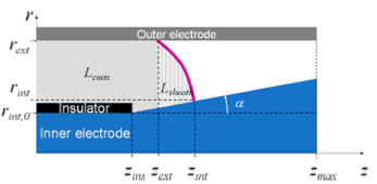
Figure 2 Geometry of the coaxial plasma accelerator in the case of a tapered inner electrode with angle α and passive and active inductance contribution diagram.
Here, rint,0 is the inner electrode radius in the zone of the insulator. As can be seen in Fig. 2, the current sheath covers an axial range delimited by the point where it touches the outer electrode, zext, and the point where it touches the inner electrode, represented by 𝑧 ins . The rundown phase, wich is the subject of this paper ends in z = zmax.
2.3.Coaxial plasma accelerator circuit
The impedance in the electrical circuit of Fig. 2 has two contributions: a fixed one given by external circuit resistance R0 and inductance 𝐿 0 , and the variable impedance formed by the resistance Rs and inductance Ls associated with the sheath shape and position along the interelectrode space. The application of Kirchoff’s voltage law to the circuit shown in Fig. 1b), yields:
Here, RSG represents the electrical resistance of the spark gap switch. Equation (2) can be expressed as two coupled first-order differential equations:
The values of R0, L0 and RSG can be considered constants over time. The inductance Ls and resistance Rs vary as the sheath travels along the coaxial electrodes. The sheath resistance Rs is assumed to be negligible, and the inductance LS is separated into two components: one given by the length of the coaxial electrodes already traveled by the current sheath, Lcoax, and an active contribution by the current sheath itself Lsheath:
In Fig. 2, regions contributing to these two inductances have been indicated. The passive contribution of the coaxial conductor array already traveled by the sheath is given by29:
The current sheath contribution to the time-dependent inductance, Lsheath, will be discussed in the following section.
2.4.The current sheath and its mass and momentum conservation
The current sheath between the two electrodes is described by a 2D curve in the (r,z) plane, as shown in Fig. 2 and in more detail in Fig. 3. The length along the current sheath will be denoted as λ. The current flows along the inner electrode, then along the current sheath and finally along the outer electrode inducing a magnetic field B in the azimuthal direction. Between the electrodes the current flows only along the sheath with a current density j, tangent curve describing the current sheath. The interaction of the current density with the magnetic field generates a perpendicular force F at each point of the sheath. In that regard, the shape and movement of the sheath will be similar to that of a perfectly elastic membrane subject to a non-isotropic pressure field with perfect slip boundary conditions. The pressure P is given by the interaction between the current in the sheath and its self-generated magnetic field:
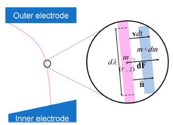
Figure 3 Definition of the differential current sheath element and the quatitites associated with it.
The force differential exerted by this pressure on a differential current sheath element dλ as shown in Fig. 3, is given by:
where
The force differential in Eq. (8) produces a linear momentum change in the differential sheath element. This linear momentum differential dp for the same element is given by:
The linear momentum differential has two contributions: one due to the acceleration, the first term in the RHS of Eq. (9), and the other due to the mass increase in the sheath element as it sweeps the volume in front of it, the second term in Eq. (9). If the sheath element is moving with velocity v and the gas in front of the current sheath element has density p, the rate of mass increase in the current sheath element according to the snowplow model is given by:
Combining Eqs. (9)-(10), the equation of motion for the differential current sheath element is obtained:
As mentioned previously, each differential element of the current sheath contributes to the time-dependent circuit inductance. The contribution of all the current sheath differential elements to the circuit inductance, Lsheath, is given by:
where θ is the angle between the vector normal to the element and the z-axis.
Equation (12) effectively couples the hydrodynamic model to the circuit model.
The inductance is a strong function of time since the sheath length and shape
varies with time. The function
3.The computational model
In order to have the complete description of the sheath motion and the circuit temporal behavior, the following set of equations needs to be solved:
The subscript i in Eqs. (13a)-(13f) indicates that there is one such equation for
each sheath element. In these equations
Equations (13a)-(13f) can be discretized in time and space, using the superscript h for the time discretization and the subscript i for sheath length discretization:
Equations (14a)-(14f) assume a constant length for the sheath segments; however, since the sheath length typically does not stay constant as it moves from the surface of the insulator towards the muzzle of the coaxial plasma accelerator, a reshaping technique 30 is used to have a constant sheath element length. A simple forward difference Euler method was used to solve Eqs. (14a)-(14f) and give the evolution of the sheath and circuit parameters over time.
4.Estimation of density and temperature in the current sheath
To obtain temperature and density estimations in the sheath, the ideal strategy would be to add an energy equation and Maxwell’s equations to the system of equations in Eq. (14). However, reasonable estimates can be obtained without resorting to adding significant complexity to the computational model presented here. Following an approach reported in the literature 31,32, it is assumed that the sheath is a normal shock wave characterized by a shock pressure PS and velocity vs corresponding to each current sheath element. For convenience we will describe the case of diatomic molecules, and specifically the case of deuterium gas. The pressure is readily available from the ideal gas law due to the particular pressure regime within the system:
where ns is the shock gas density,
In the case of deuterium, the effective atomic number Zeff is a number between 0 and 2, dependent on the degree of ionization. The application of the Rankine-Hugoniot jump conditions 33 yield expressions that relate the parameters of the current sheath (number density ns and velocity vs) with the corresponding values of the neutral gas (n0 and v0):
The parameter 𝛾 is the heat capacity ratio, which for the case of an ideal gas is equal to 5/3 34. In normal shock theory the shock pressure and its speed and density are related if the pressure in the sheath and the gas are small:
The molecular weight Mw and Avogadro’s number NA are required to switch between particle number density and mass density, the latter being the quantity typically used in normal shock analysis. Substitution of the previous equations in Eq. (15) yields an expression for the shock temperature in terms of the sheath velocity, already known from the snowplow calculation:
From the total mass m i accrued on each current sheath, the mass density of each sheath element is given by:
where δ i and A i are the thickness and surface area (the latter obtained by rotating the differential sheath element around the central axis). The density can be estimated from Eqs. (17a) and (17b):
Using the last two expressions, the sheath element thickness δ i is obtained:
According to Eq. (22), the thickness is independent of the shock parameters. A dependence with temperature can be introduced by considering an expression for the heat capacity ratio in partially ionized gases 35:
Once the shock temperature is known from Eq. (19), the Saha equation is used to estimate the electron density n e in the shock region:
5.Results
5.1.Effect of electrode taper on plasma acceleration
In order to study the effect of the taper of the inner electrode on the sheath characteristics, its motion between electrodes with different taper angles was described using the numerical model described in the previous section. The configurations are shown in Fig. 4. Figure 4a) shows the case of a straight inner electrode (a solid cylinder) with a sleeve insulator shown in gray on the left and the outer electrode starting on the back of the insulator. In Fig. 4b) a similar arrangement is shown, but the inner electrode now has a negative taper. Finally, Fig. 4c) shows an inner conical electrode with positive taper angle. For the simulations, the taper angle was varied from -5o to +5oin 1o increments.
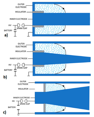
Figure 4 Inner electrode and insulator geometry. a) straight electrode with sleeve insulator; b) negative -5o taper with sleeve insulator; and c) positive +5o taper with sleeve insulator.
The geometry and circuit parameters for the simulation are listed in Table I. This set of parameters were selected to initially benchmark the calculations done with this model against similar studies already reported 36. A good agreement was found between the results of the finite difference scheme used here and the behavior reported in the literature for the case of the straight electrode (0otaper). This means that the results obtained from simulations considering tapered inner electrodes are reliable.
Table I Set of electrode parameters used for the calculations in the case of the straight electrode (0o taper) with sleeve insulator.
| Parameter (unit) | Value |
| Insulator length (cm) | 3.4 |
| Electrodes length (cm) | 13 |
| Insulator outer radius (cm) | 1.7 |
| Inner electrode radius (cm) | 1.2 |
| Outer electrode radius (cm) | 2.4 |
| Circuit inductance (nH) | 75 |
| Capacitance (F) | 7.2 |
| Circuit resistance (m Ω) | 3 |
| Neural gas density (kg/m3) | 4.8 x 10⁻⁴ |
| Charging voltage (kV) | 25 |
The plasma breakdown and evolution of the rundown phase at the start of the simulation are similar, but as the sheath advances and approaches zmax, its shape and length differ in accordance to the taper. Figure 5 shows a schematic of the sheath shape as it reaches the end of inner electrodes with -5, 0 and 5o taper angles.
Figure 6 shows the magnetic force as a function of time for different values of the taper angle. As can be seen, the radial distance plays an important role, giving much higher magnetic force for the negative taper electrodes. All simulations are run until the sheath reaches z = zmax, and Fig. 7 clearly shows another important characteristic introduced by the taper angle: the sheath transit time is affected by the electrode geometry.
Figure 6 Evolution of the total magnetic force on the sheath current for three different taper angles.
Figure 7 Transit time for the sleeve insulator as a function of taper angle. The current sheath reaches the inner electrode end earlier for negative angles with the sleeve insulator.
Figure 7 shows the sheath transit time as a function of taper angle. The sheath travels the length of the inner electrode in 1.25 μs for the convergent electrode, and it takes 1.6 μs for the 5odivergent electrode, a 30% increase. This finding is counterintuitive, since the convergent electrodes (negative values of taper angle) sweep more gas and therefore acquire more mass, as shown in Figs. 8 and 1. However, by looking at Fig. 6, it can be seen that the increase in magnetic force for lower values of the taper angle causes a higher energy injection into the sheath, which allows for a sheath with 5 times more mass to reach the same velocity.
Figure 8 Total mass swept by the current sheath upon reaching the end of the electrode as function of taper angle.
The estimation of temperature and electron density in the sheath allows for the calculation of the internal energy. The internal energy of the sheath is calculated as:
where the sum is over the segments of the discretized sheath. Table II presents the peak and average values of density and temperature of the sheath when it reaches the end of the inner electrode for the extreme taper angle cases and the straight electrode. The temperature and density values obtained with this computational model are consistent with those reported on the literature for both simulations and experiments 32,37-39. Figure 9 shows the internal energy of the sheath when it reaches the end of the inner electrode as a function of taper angle. There is not a great variation in total internal energy, oscillating between 0.6 and 0.9 J in the taper angle range. However, as the taper angle gets more positive, the sheath sweeps less mass due to the decrease in separation between the electrodes. Therefore, for a given internal energy of the sheath, the internal energy per unit mass will be higher for the divergent electrodes since it gets divided by a smaller number.
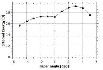
Figure 9 Sheath internal energy as function of taper angle when the end of the inner electrode is reached.
Table II Peak and average values of temperature and density in the current sheath at the end of the simulation.
| Taper Angle | Peak Temperature | Peak density | Average Temperature | Average density |
| (deg) | (eV) | (m−3) | (eV) | (m−3) |
| -5 | 97.5 | 8.75E23 | 7.02 | 2.40E22 |
| 0 | 32.8 | 5.05E23 | 8.32 | 4.41E22 |
| 5 | 16.8 | 2.31E23 | 11.24 | 1.03E23 |
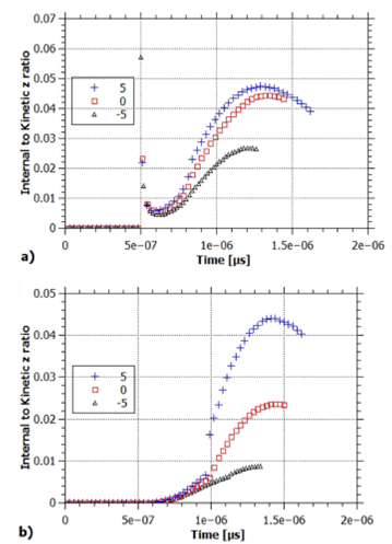
Figure 10 presents the ratio of total internal to kinetic energy for -5, 0 and 5otaper angles as the sheath moves along the interelectrode space. The lowest value of the ratio (0.6%) corresponds to the convergent electrode, while the highest value (2.3%) corresponds to the divergent electrode. The divergent electrode presents the higher ratio because it has the lowest kinetic energy (it has the longest transit time and the smallest mass) and, according to Table IIand Fig. 9, it has a higher average internal energy. It can be concluded that while the convergent electrode has a higher kinetic energy, the divergent electrode is 4 times more efficient in transforming the energy transferred to the sheath into internal energy.
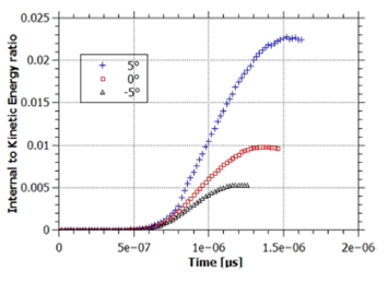
Figure 10 Time evolution of the internal to kinetic energy ratio for three inner electrode configurations: convergent (-5o), straight (0o) and divergent (5o).
The values from Table IIsuggest that there is inhomogeneity in the density and temperature along the sheath, especially for the convergent electrode, which shows a significant difference between the average and peak values. Figure 11 shows the distribution of density and temperature along the sheath for -5, 0 and 5oelectrode taper angle. To allow for a better comparison of the profiles between cases, density and temperature are normalized against their peak values (which always occur at the point of contact with the inner electrode), and the length coordinate is normalized to the total length of the sheath for each case, such that coordinates in both axis are between 0 and 1. Indeed, a strong temperature and density gradient along the sheath for the negative taper angle can be observed in Fig. 11, with the highest values close to the electrode; there, according to Table II, the electron temperature is close to 100 eV and the density is on the order of 1024m-3. For the sheath end near the outer electrode, all three cases have nearly the same value for temperature (∼10 eV) and density (1023 m-3).
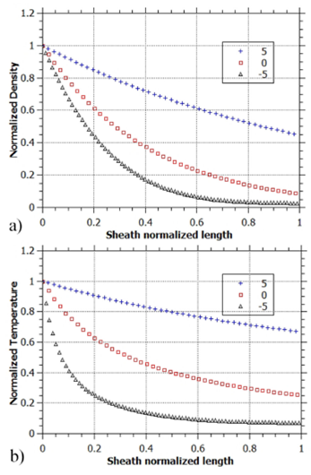
Figure 11 Normalized density and temperature profiles along the length of the sheath when it reaches the end of the electrode. Curves are for convergent (-5o), straight (0o) and divergent (5o) inner electrode.
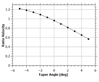
It is clear that a convergent electrode yields a sheath with higher kinetic energy, but it is interesting to explore how that velocity is imparted. For applications involving plasma projections into targets, a sheath with a high axial velocity component and a low radial velocity would be preferred. Therefore, a small ratio of radial to axial velocity is desired. Figure 12 shows the radial to axial average velocity ratio as a function of taper angle when the sheath reaches the end of the inner electrode. The ratio presents an inverse proportionality with taper angle.
Effect of insulator configuration on the current sheath behavior
The most common configuration for the insulator in coaxial plasma accelerators is a cylindrical sleeve around the start of the inner electrode, as shown in Fig. 4. The initial phase of the sheath movement implies acquiring velocity in the radial direction to detach from the insulator. To explore how sensitive the sheath evolution is to initial acceleration conditions, a different insulator geometry was simulated. Figure 13 shows the two-insulator configurations that will be compared: the sleeve-type insulator (Fig. 13a), where the insulator surface normal points in the radial direction; and the plug-type insulator (Fig. 13b), where the insulator surface normal points in the axial direction.
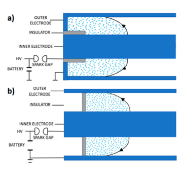
Figure 13 Two insulator configurations for the coaxial plasma accelerator: a) sleeve insulator, b) plug insulator.
Physically, the sleeve-type insulator is a thin cylindrical shell with a given length, while the plug-type insulator is a thin hollow disk with given inner and outer radiuses. Results presented in the previous section correspond to the sleeve insulator, and the same sensitivity analysis for the taper angle was carried out for the other sheath initial condition, along a constant z surface rather than a constant r surface. The circuit, energetics and mass swept are not affected by the new boundary condition. The most important difference between the two configurations was found in the velocity distribution of the sheath.
Figure 14 shows the ratio of average axial to radial velocities for the last sheath as a function of taper angle, while Fig. 15 shows the local ratio along the sheath when it reaches the end of the electrode for -5, 0 and 5ofor both sleeve and plug insulator configurations. For the sleeve type insulator, the sheath at the end of the electrodes has a radial to axial velocity ratio close to 2 in the zone near the outer electrode, an effect more pronounced in the convergent electrode which has a longer sheath. By switching to the plug type insulator (Fig. 15b), a drastic reduction on the ratio is observed, with a peak value of 1.2 near the middle of the sheath. The average radial to axial velocity ratio for the -5oconvergent electrode with plug-type insulator drops 30% in comparison to the same electrode with a sleeve-type insulator, leaving it with a value of 0.8. The switch from a sleeve-type insulator to a plug-type insulator removes one of the main drawbacks of a convergent electrode configuration.
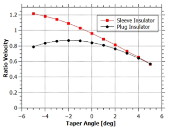
Figure 14 Comparison of the ratio of radial to axial component of the final average velocity of the sheath for sleeve-type and plugtype insulators.
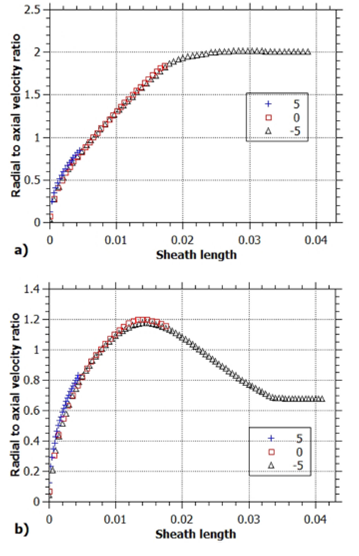
Figure 15 Comparison of local ratio of radial to axial component along the sheath when it reaches the inner electrode end for three inner electrode configurations: convergent (-5o), straight (0o) and divergent (5o). a) Sleeve-type, b) plug-type.
It is clear that the effect of switching to a plug-type insulator is to promote the kinetic energy in the forward direction. To highlight this fact, a comparison between kinetic and internal energy is done; however, rather than taking the ratio of internal to total kinetic energy as before (as shown in Fig. 10), now the kinetic energy in the forward (z component) direction will be considered. Figure 16 compares the evolution of this internal to forward kinetic energy ratio as the sheath travels for the two types of insulator when a straight electrode is used. The plug configuration shows slight discontinuities associated with mass loss due to the blow-by effect 37.
6.Conclusions
A 2D computational model has been developed for the study of the rundown phase of a current sheath traveling in the space between two coaxial electrodes. The code allows for the introduction of a taper angle in the inner electrode, such that it can represent a conical rather than a cylindrical surface. The cone can be either convergent or divergent, and both scenarios were explored here.
It was found that the negative taper configuration (convergent electrode) transfers a larger amount of average linear momentum to the current sheath: it sweeps more mass and has a lower transit time; this is explained by the magnetic force increase associated with the convergent electrode. However, the sheath momentum upon reaching the end of the inner electrode region has a large radial component, which is undesirable when the goal is to transfer forward momentum. In that regard, the divergent electrode gives a better performance, since the radial to axial velocity ratio decreases as taper angle increases.
Internal to kinetic ratio also was found to increase with increasing taper angle, and this increase was mostly due to the mass reduction as the taper angle increases, and not to significant changes in temperature and density parameters, since for all taper angles the average values of these quantities remain within the range 15-20 eV and 1022-1023 m-3 for temperature and density, respectively. Although the average values of density and temperature are similar, it was found that the long sheaths associated with more negative taper angle values present high densities and temperatures near the inner electrode and low values near the outer one, with the peak temperature (at the contact point with the inner electrode) being 20 times higher than that calculated at the point where it touches the outer electrode, and the density being 10 times higher between those two points.
The switch from a sleeve-type insulator to a plug-type insulator seems to promote kinetic energy transfer to the sheath in the axial direction, since a reduction in the ratio of radial to axial component of the final average velocity of the sheath was found, especially for convergent electrodes. This trend was also observed for the ratio of internal energy to forward kinetic energy; the -5 degree taper angle (convergent) electrode with a plug insulator has a ratio 65% lower than the same electrode with the sleeve configuration. The ratio is the same for both insulator configurations when the taper angle is 5 degrees (divergent).

