


Servicios Personalizados
Revista
Articulo
 Inglés (pdf)
 Artículo en XML
 Referencias del artículo
 Enviar artículo por email
Indicadores
-
 Citado por SciELO
 -
 Accesos
Links relacionados
-
 Similares en
SciELO
Similares en
SciELO
Compartir

 Permalink
Revista mexicana de ingeniería química
versión impresa ISSN 1665-2738
Rev. Mex. Ing. Quím vol.10 no.1 Ciudad de México abr. 2011
Fenómenos de transporte
Assessment of the local hydrodynamic zones in a three–phase airlift reactor: looking for the lowest liquid–phase Re
Evaluación de las zonas hidrodinámicas locales en un reactor airlift trifásico: buscando el Re de fase líquida más bajo
M.A. Lizardi–Jiménez* and M. Gutiérrez–Rojas
Departamento de Biotecnología, Universidad Autónoma Metropolitana–Iztapalapa, Av. San Rafael Atlixco No. 186 Col. Vicentina, C.P. 09340, Ciudad de México, México. *Corresponding author. E–mail: cbs204381858@xanum.uam.mx Tel. + 52 (55) 5804 6505, Fax + 52 (55) 5804 6407
Received 6 of October 2010.
Accepted 2 of February 2011.
Abstract
Hydrodynamic in main airlift reactor (ALR) zones (riser and downcomer) was evaluated in order to find the lowest Reynolds number (Re) in a three–phase ALR. In our study, three phases were identified: one gaseous (air) and two liquids (oil and aqueous). Two Re of the liquid species, one for each phase, were defined: Reaq and Reoil corresponding to the aqueous and oil phase, respectively. Since gas phase was considered by hold up (εg) in our work. In 10 L ALR, riser showed turbulent aqueous phase flow (4000 < Reaq < 9000) whereas downcomer exhibited non–turbulent flow (1250 < Reaq < 4000). Reoil in riser (5000 < Reoil < 10000) was higher than Reaq; whereas in downcomer, Reoil was lower than Reaq (200 < Reoil < 2200). The oil phase into the downcomer zone was demonstrated to be the most important hydrodynamic constraint and consequently limited mass transfer should be expected. The complexity of three–phase flow and the limited measurement technologies have generated few studies regarding the local hydrodynamics properties restricting three–phase reactors optimization and commercialization: our study is a contribution to identify such restrictions.
Keywords: airlift, hydrodynamics, riser, downcomer, three–phase, Re.
Resumen
Se evaluó la hidrodinámica en las principales zonas (ascenso y descenso) de un reactor airlift (ALR) trifásico para encontrar el numero de Reynolds (Re) más bajo. Las fases del estudio fueron: una gaseosa (aire) y dos líquidas (hidrocarburos y agua). Se definieron dos Re en las fases líquidas: Reaq y Reoil correspondientes a las fases acuosa y oleosa. La fase gaseosa fue considerada mediante el coeficiente de retención (εg). En el ALR (10 L) la zona de ascenso mostró flujo turbulento (4000 < Reaq < 9000) mientras que en la zona de descenso no se observó flujo turbulento (1250 < Reaq < 4000). El Reoil en la zona de ascenso (5000 < Reoil < 10000) fue mayor que el Reaq; mientras que en la zona de descenso fue menor (200 < Reoil < 2200). La fase oleosa en la zona de descenso fue la limitante hidrodinámica y consecuentemente se debería esperar una limitación en la transferencia de masa. La complejidad del flujo trifásico y las limitadas tecnologías para su medición han generado pocos estudios relacionados con las propiedades hidrodinámicas locales restringiendo la optimización y comercialización de los reactores trifásicos; nuestro estudio es una contribución a la identificación de este tipo de restricciones.
Palabras clave: airlift, hidrodinámica, ascenso, descenso, trifásico, Re.
1 Introduction
Airlift reactor (ALR) is a pneumatic reactor agitated with a continuous gas phase provided in form of bubbles, breaking–up towards the liquid phase resulting in an isothermal expansion to keep homogeneity (Chisti, 1989). In case of ALR performance, attention has been focused on two fundamental phenomena: (i) agitation for well mixed liquid phases (Gumery et al., 2009) and (ii) oxygen mass transfer considering geometrics in internal loop reactors (Cerri et al., 2010) and CFD simulations (Huang et al., 2010; Luo et al., 2011). Agitation and mixing is often related to the Reynolds number (Re) as a global hydrodynamic parameter i.e., a bulk Re or a liquid phase Re (Wongsuchoto and Pavasant, 2004). Recent studies in ALR allow emphasizing the role of aqueous phase Re in two–phase ALR performance. Unfortunately, none of the works is oriented to study the different local hydrodynamic zones. For all types of ALR, it is possible to distinguish four different local hydrodynamic zones: riser, downcomer, top and bottom clearance (see Fig. 1). Although the hydrodynamic importance of zones in ALR performance is well documented (Sánchez–Mirón et al., 2004; Kilonzo et al., 2006) most of ALR studies neither take into account zones or non–soluble aqueous substrates (e.g. oil) in three–phase systems. Studying aqueous and oil phase hydrodynamics in main three–phase ALR zones is very important because hydrodynamic is strongly implicated in both, aqueous soluble and non–soluble substrates and mass transfer phenomena and the resulting ALR performance; for example, bioengineering and oil biodesulfuration purposes (Mehrnia et al., 2005; Shariati et al., 2007) or using silicone oil as an effective mass transfer vector (Quijano et al., 2009). The aim of this work is to assess, in a trhee–phase ALR, the local hydrodynamic zone (riser or downcomer) with lower Re by measuring fluid velocities in the aqueous and oil phases.

2 Materials and methods
2.1 Reactor
A 10–L operation volume airlift reactor (ALR) was used. The ALR cylindrical vessel was built in Pyrex glass (0.005 m of wall thickness). Gas phase was introduced into the ALR draft tube. Draft tube was located 0.035 m above the bottom. Geometrical relations and the flow pattern are shown in Fig. 1, in brief: D1 and D2 are reactor (0.14 m) and draft tube (0.09 m) diameter, respectively; L1 and L2 represent reactor (0.70 m) and draft tube (0.54 m) height; riser, top clearance, downcomer and bottom clearance are identified. Geometrical relations: D2/D1 = 0.65, L2/L1 = 0.77 and L1/D1 = 5 were used.
2.2 Gas sparger
Air was sparged through the draft tube with an L–form perforated (7 orifices; 0.001 m of diameter and 0.004 m of separation) stainless steel tubing (0.006 m internal diameter) driving out air downwards.
2.3 Two–liquid phase model medium
In order to adjust surface tension (σ), a model medium was designed using reference values (50 – 65 dynes cm–1) as suggested elsewhere (Bai et al., 1997; Quijano et al., 2010) by adding different Tween 20 (0–0.15 mL L–1) concentrations and 13g L–1 of hexadecane (HXD). σ was measured with a Manual Fisher Surface Tensiometer Model 20 (Fisher Scientific International, Wisconsin, USA). Viscosity (μ) was determined by using a viscometer Physica MCR Model 300 (Sttuttgart, Germany).
2.4 Hydrodynamic parameters
2.4.1 Gas hold up
Gas hold up (εg) was evaluated into riser and downcomer by photographic method (Ribeiro and Lage, 2004) using a digital camera (Pentax Optio 50) and image analysis software (Image Pro plus 4.1).
2.4.2 Aqueous and oil phase hydrodynamic
Three phases (air, aqueous and oil) were involved in ALR, the two slow–moving phases (aqueous and oil) velocities were experimentally evaluated. In order to clearly follow flow patterns thorough model medium, we used two substances simulating water (sodium polyacrylate hydrogel; ρ = 1.0 g cm–3) and oil (oligosyloxane stained spheres; ρ = 0.77 g cm–3). A digital videocamera (Sony HD) and on–line chronometer (StopWatch software) were used to monitoring velocities of single spheres as path length/elapsed time ratio in both ALR zones: riser and downcomer. In order to contrast sphere images, HXD was previouslystained with red chillies (Capsicum annuum) oleoresin (Montoya–Ballesteros et al., 2010), also known as rodophile (Bioquimex–Reka, México; 25.1 g of carotenoid kg–1) (see Fig. 2). The resulting velocities were used to calculate two individual Reynolds numbers (Nielsen et al., 2003) as follows:
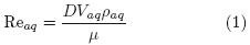
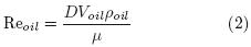
Where: Reaq and Reoil are aqueous and oil phase Reynolds number, respectively. D = D2 for riser zone; and D = (D1–D2) for downcomer zone; D1 is the ALR diameter, cm; D2 draft tube diameter, cm; Vaq aqueous phase velocity, cm s–1; Voil oil phase velocity, cm s–1; ρaq aqueous phase density, g cm–3; ρoil oil phase density, g cm–3; μ bulk viscosity (oil in water emulsion), g cm s–1. In order to validate our method, the Vaqd values obtained were compared with acid pulse method (Sanchez– Miron et al., 2004) . Chisti model (Chisti et al., 1988; Abashar et al., 1998) and the continuity criterion (Chisti, 1989) was used in order to predict superficial aqueous phase velocity (Vaqd) into downcomer using εg as follows:
Where: Ar and Ad are cross section area for riser and downcomer, m2, respectively. εgr and εgd are gas hold up in riser and downcomer, dimensionless, respectively, K is the loss friction coefficient, dimensionless, g is the gravitational acceleration constat, m s–2 and LD is the draft tube lenght, m.
The model assumes the following: (1) steady–state conditions, (2) isothermal conditions, (3) the energy losses terms due to the skin friction in the riser and the downcomer are negligible in comparison to the others dissipation terms, (4) the presure drop due to acceleration is negligible.
2.4.3 Statistical analyses
Data analyses were carried out by using NCSS–2000, version 2001 (Copyright 2001 by Jerry Hintze). Analysis of variance (ANOVA) was performed by comparing tests with p < 0.05.
3 Results and discussion
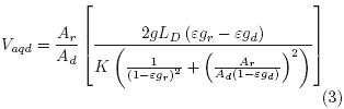
In order to evaluate hydrodynamic behavior in our three–phase ALR, εg, liquid phases velocities, Reaq and Reoil were measured using geometrical relations D2/D1 = 0.65 and L2/L1 = 0.77. The choice of this configuration is partially according to a similar hydrocarbon/liquid ALR (Gumery et al., 2005) studying dynamics and macro–mixing for design and scale–up purposes. Fig. 3 shows εg as a function of Ug into riser and downcomer. The εg in the riser was slightly higher than in the downcomer. A potential model: εg = aUgb (where a and b depend on local hydrodynamic) was used for both: riser (a = 0.053 and b = 0.74; R2 = 0.99) and downcomer (a = 0.045 and b = 0.72; R2 = 0.98). The differences between εg in riser and downcomer caused liquid phases circulation. The potential model data obtained from Fig. 3 were used in order to predict superficial aqueous phase velocities into downcomer (Vaqd) using the Chisti model, see Eq. 3. Fig. 4 shows experimental data of Vaqd as a function of Ug in addition to Vaqd values predicted by the Chisti model. A good fitting value for the loss friction coefficient (K) of 4, close to other work (1.8) with water and kerosene (Abashar et al., 1998), was found.
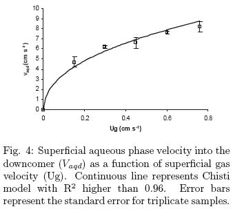
Fig. 5 shows Reaq as a function of Ug and σ, for the selected configuration in riser (3a) and downcomer (3b). As expected, in riser and downcomer, Re increased as Ug increased. On the other hand Reaq slightly decreased as σ increased. A similar performance was also observed in other pneumatic reactors working with two–phase systems (Kantarci et al., 2005). Riser shows turbulent flow (Reaq > 4000; see red zone in Fig. 2a) when Ug was higher than 0.4 cm s–1, whilst downcomer do not (red zone is absent in Fig. 3b). Reaq increased as Ug probably due to differences in gas hold up between riser and downcomer, which produces differences in hydrostatic pressure at the ALR bottom, these differences in hydrostatic pressure produce the liquid phase being in continuos movement. The Reaq decreasing as surface tension increased could be explained by reason of gas hold up decreased as a result of larger bubbles with lower residence time and the resultant decreasing in the differences in hydrostatic pressure. Moreover, lower Reaq in downcomer (not turbulent) supposes a hydrodynamics limitation for mixing probably imposing mass transfer limitation (Nielsen et al., 2003); this limitation is worst for oil phase as can be seen in figs. 3c and 3d. Figures show Reoil as a function of Ug and surface tension. Reoil in riser (5000 < Reoil < 10000) (Fig. 3c) was higher than Reaq; whereas in downcomer was lower (200 < Reoil < 2200) (Fig. 3d). Reoil in riser and downcomer were higher and lower than Reaq, respectively, due to densities differences. Lower Reoil values in downcomer involve an increasing in boundary layer between oil and aqueous phase, probably resulting in mass transfer constraints (Cerri et al., 2010). Our results suggest that a carefully evaluation of the two Re species, involved in performance of three–phase ALR was needed since oil phase into the downcomer supposed a clear hydrodynamic and probably mass transfer limitation. Traditional two–phase model that considers only aqueous phase is not enough to explain oil in water reactors. For example, oil–degrading microorganism growth (Medina–Moreno et al., 2009) should consider oil transfer constraints in the bulk. The complexity of three–phase flow and the limited measurement technologies have generated few studies regarding the local hydrodynamics properties restricting three–phase reactors optimization and commercialization.
Conclusion
Aqueous and oil phase Re for main ALR local hydrodynamics zones, riser and downcomer, in a three–phase ALR were evaluated in this work. Riser shows turbulent aqueous phase flow: 4000 < Reaq < 9000 for 0.15 < Ug < 0.76 cm s–1 whereas downcomer shows non–turbulent aqueous phase flow: 1250 < Reaq < 4000 at the same above mentioned Ug values. Oil phase Re in riser (5000 < Reoil < 10000) was higher than Reaq; whereas in downcomer, Reoil was lower than Reaq (200 < Reoil < 2200). Reoil into downcomer zone is supposed to be the most important hydrodynamic constraint allowing us to identify the downcomer as a relevant mass transfer limitation zone.
Acknowledgements
We acknowledge CONACYT (Consejo Nacional de Ciencia y Tecnología) by scholarship to M. A. Lizardi–Jimenez and PEMEX–Refinación for partial support. Thanks are due to Dr. J. Vernon in providing rhodophile pigment solution.
References
Abashar, M.E., Narssing, U., Rouilliard, A. E. (1998). Hydrodynamic Flow Regimes, Gas Holdup, and Liquid Circulation in Airlift Reactors. Industrial and Engineering Chemistry Research 199, 1251–1259 [ Links ]
Bai, G., Brusseau, M.L. and Miller, R.M. (1997). Biosurfactant–enhaced removal of residual hydrocarbon from soil. Journal of Contaminant Hydrology 25, 157–170. [ Links ]
Cerri, M.O., Policarpo, L.M. and Badino, A. C. (2010). Gas Hold–Up and mass transfer in three geometrically similar internal loop airlift reactors using newtonian fluids. International Journal of Chemical Reactor Engineering 8, 1–14. [ Links ]
Chisti, Y. Halard, B., Moo–yung, M. (1988). Liquid circulation in airlift reactor. Chemical Engineering Science 43, 451–456 [ Links ]
Chisti, Y. (1989). Airlift Bioreactors. Elsevier Science Publishers, New York. [ Links ]
Gumery, F., Ein–Mozaffari, F. and Dahman, Y. (2009). Characteristics of local flow dynamics and macro–mixing in airlift column reactors for reliable design and scale–Up. International Journal of Chemical Reactor Engineering 7, 1–45. [ Links ]
Huang, Q., Yang, C, Yu, g., Mao, Z. (2010). CFD simulation of hydrodynamics and mass transfer in an internal airlift loop reactor using a steady two–fluid model. Chemical Engineering Science 65, 5527–5536. [ Links ]
Kantarci, N., Borak, F. and Klutlu, O. (2005). Bubble column reactors. Process Biochemistry 40, 2263–2283. [ Links ]
Kilonzo, P.M., Margaritis, A., Bergougnou, M.A., Yu, J.T. and Qin, Y. (2006). Influence of the baffle clearance design on hydrodynamics of a two riser rectangular airlift reactor with inverse internal loop and expanded gas–liquid separator. Chemical Engineering Journal 121, 17–26. [ Links ]
Luo, H.P., Al–Dahhan, H. (2011). Verification and validation of CFD simulations for local flow dynamics in a draft tube airlift bioreactor. Chemical Engineerig Science 66, 907–923. [ Links ]
Medina–Moreno, S.A., Huerta–Ochoa, S., Lucho–Constantino, C.A., Aguilera–Vázquez, L., Jiménez–González, A. and Gutiérrez–Rojas, M. (2009). Biodegradation modeling of sludge bioreactors of total petroleum hydrocarbons weathering in soil and sediments. Revista Mexicana de Ingeniería Química 8, 245–258. [ Links ]
Mehrnia, M., Towfighi, J., Bonakdarpour, B. and Akbainejad, M. (2005). Gas hold–up and oxygen transfer in a draft–tube airlift bioreactor with petroleum based liquids. Biochemical Engineering Journal 22, 105–110. [ Links ]
Montoya–Ballesteros, L.C., Gardea–Béjar, A., Ayala–Chávez G.M., Martínez–Nunez Y.Y. and Robles–Ozuna, L.E. (2010). Capsaicinoids and color in chilpetin (Capsicum annuum var. aviculare). Processing effect on sauces and pickles. Revista Mexicana de Ingeniería Química 9, 197–207. [ Links ]
Nielsen, J., Villadsen, J. and Liden, G. (2003). Mass transfer. In: Bioreactor Engineering Principles. Kuwler Academic/Plenum Publishers, New York. [ Links ]
Quijano, G., Revah, S., Gutiérrez–Rojas, M., Flores–Cotera, L. and Thalasso F. (2009). Oxygen transfer in three–phase airlift and stirred tank reactors using silicone oil as transfer vector. Process Biochemistry 44, 619–624. [ Links ]
Quijano, G., Huerta–Ochoa, S. and Gutiérrez–Rojas, M. (2010). Assessment of the limiting step of mass transfer in n–hexadecane biodegradation in a bubble column reactor. Water Science and Technology 62, 906–914. [ Links ]
Ribeiro, Jr C. P. and Lage, P. L. C. (2004). Experimental study on bubble size distributions in a direct contact evaporator. Brazilian Journal of Chemical Engineering 21, 69–81. [ Links ]
Sanchez–Mirón, A., Cerón–Garcia, M.C, Garcia–Camacho, F., Molina–Grima, E. and Chisti, Y. (2004). Mixing in bubble column and airlift reactors. Transactions Institution of Chemical Engineers Part A. Chemical Engineering Research and design 82, 1367–1374. [ Links ]
Shariati, F.P., Bonakdarpour, B. and Mehrnia, M.R. (2007). Hydrodynamics and oxygen transfer behaviour of water in diesel microemulsions in a draft tube airlift bioreactor. Chemical Engineering and Processing 46, 334–342. [ Links ]
Wongsuchoto, P. and Pavasant, P. (2004). Internal liquid circulation in annulus sparged internal loop airlift contactors. Chemical Engineering Journal 100, 1–9. [ Links ]

