


Servicios Personalizados
Revista
Articulo
 Inglés (pdf)
 Artículo en XML
 Referencias del artículo
 Enviar artículo por email
Indicadores
-
 Citado por SciELO
 -
 Accesos
Links relacionados
-
 Similares en
SciELO
Similares en
SciELO
Compartir

 Permalink
Revista de la Sociedad Química de México
versión impresa ISSN 0583-7693
Rev. Soc. Quím. Méx vol.48 no.1 Ciudad de México ene./mar. 2004
Investigación
Nanofiltration Membrane Pore Diameter Determination
Heriberto Espinoza-Gómez,*(a) Shui Wai Lin,(b) Eduardo Rogel-Hernández(a)
a) Facultad de Ciencias Químicas e Ingeniería, Universidad Autónoma de Baja California-Tijuana, Calzada Tecnológico no. 14418, C.P. 22390. Tijuana, B. C. México. Telephone ++(52 664)682 27 90. E-mail jhespinoza@uabc.mx
b) Centro de Graduados e Investigación del Instituto Tecnológico de Tijuana, Apdo. Postal 1166, Tijuana, B. C. México.
Recibido el 12 de enero del 2004.
Aceptado 20 de febrero del 2004.
Abstract
This paper present a method to determine pore diameters and effective transport through membranes using a mixture of oligosaccharides. The results are compared with the Maxwell-Stefan equations. The partition coefficients of the solutes are a function of the pore diameter according to the Ferry equation. Thus, with the pore diameter as the only unknown parameter, rejection is described and the pore diameter is obtained by a Marquardt-Levenberg optimization procedure.
Key words: Membrane pore diameter determination, oligosaccharides measurements, nominal molecular weight cut-off determination.
Resumen
Se presenta un método para determinar el diámetro de poro y transporte efectivo de masa a través de membranas, empleando una mezcla de oligosacáridos. Los resultados se comparan con la ecuación de Maxwell-Stefan. Los coeficientes de partición de los solutos son función del tamaño de poro, de acuerdo con la ecuación de Ferry. El diámetro de poro se determina como único parámetro desconocido, el rechazo y el diámetro de poro se obtienen mediante el procedimiento de optimización de Marquardt-Levenberg.
Palabras clave: Determinación del diámetro de poro de membranes, medición de oligosacaridos, determinación de peso molecular límite nominal.
Introduction
The separation characteristics of nanofiltration and ultrafiltration membranes are usually expressed in terms of the NMWC (nominal molecular weight cut-off). The manufacturer supplies this NMWC, usually without detailed information on the method of determination. It is often unclear which solute is used or under which conditions the determinations have been carried out. For this reason, it is not easy to obtain reliable information on the separation characteristics of a membrane from the NMWC alone. Therefore, the user has to carry out additional experiments to characterize the membrane. For an analysis of the separation characteristics structural parameters of a membrane (pore diameter, effective pore length, membrane porosity and charge density), which are independent of the applied conditions, need to be established.
Nakao et al [1]. show that the pore diameter and the ratio of effective pore length to membrane porosity (i.e. the effective transport length) can be obtained from rejection measurements with uncharged solutes. Hanemaaijer et al.[2]. show that filtration of oligosaccharides is a successful method for the determination of mean effective pore sizes. Bowen et al. [3] Compare pore diameters determined from experiments with uncharged solutes with data from Atomic Force Microscopy (AFM) analysis. The diameters obtained with AFM are about half of those as fitted from experimental data. Both Bowen et al [3]. and Nakao et al.[1] report problems with the determination of the effective transport length, τz/ε. This parameter is overpredicted when it is calculated from the hydraulic permeability obtained from independent clean water flux measurements. Only a simultaneous fit of the pore diameter and the effective transport length and using the hydraulic permeability from the same experiment provides successful descriptions of the experimental results.
In this paper it is shown that with a clean water flux experiment and one single experiment, using a dilute mixture of oligosaccharides, the membrane characteristics can be determined. The membrane characteristics are expressed in a mean effective pore diameter and the effective transport length. From the clean water flux experiment the hydraulic permeability is determined, while the other experiment is used to establish the pore diameter. The pore diameter determines the distribution of solutes over liquid and membrane phase and the friction with the membrane pore walls. The pore diameter is determined by comparing experimental results to predictions based upon a Maxwell-Stefan representation of membrane filtration, which is described in the theory section. The friction of solutes with the pore wall is estimated by analogy with the reduction in falling velocity of spheres in narrow tubes. From this analysis, pore diameter and the effective transport length, τz/ε, are successfully obtained.
Theory
To establish the pore diameter and the effective transport length, flux and solute ejections at various transmembrane pressures have to be determined. For an analysis of the results we use a theoretical model as described by Vonk, et al. [4], and Noordman, et al. [5]. In this model, the membrane is considered to be heterogeneous, which means that pores are a separate phase next to the membrane phase. The model is a combination of transport relations, mass balances, partition relations and constraint relations.
Transport
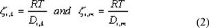
We start with a description of diffusive transport by the Generalized Maxwell Stefan equation [6,7] For an uncharged component i this equation is written as:

Equation (1) is a force balance, in which the driving force on component i is given on the left hand side. The driving force is equal to the chemical potential gradient, separated into its composition-dependent and pressure-dependent part. Due to this gradient, component i is transported and will experience friction from the other components in the system, which is described by the terms on the right hand side of equation (1). This friction is proportional to both the mole fractions and the velocity difference of the components. The friction between solvent and the membrane, and solute and the membrane also has to be considered. Therefore, the membrane is taken as an extra component in the system. In the applied reference frame, the membrane is immobile and its velocity equals zero. The mole fraction of the membrane cannot be determined and for this reason is combined with the friction coefficient to obtain an overall friction coefficient zi,m.
In equation (1) the diffusive volume fluxes of the components are indicated by the symbol u and are expressed in m3 per m2 of total membrane area. To obtain real component velocities these have to be divided by a factor ε/τ, in which ε is the porosity of the membrane and τ the tortuosity. The diffusive friction coefficients, zi,k, are related to the binary diffusivities by:
In pressure driven membrane processes both diffusive transport and viscous flow are important.
The viscous flow can be described by:
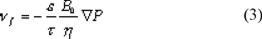
B0 is the permeability of the membrane. For Poiseuille flow through cylindrically shaped pores B0 is equal to rp2 / 8. The total velocity of component i, wi, is equal to the sum of its diffusive and viscous part: wi = ui+ nf. We can substitute this in the Maxwell-Stefan equation, which yields:
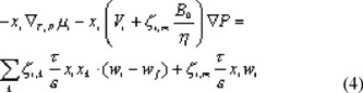
The component velocities wi are converted to molar fluxes Ni with the following equation:

We obtain the transport equation in terms of molar fluxes after substitution of eqn. (5) into eqn. (4):
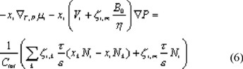
Concentration polarization is important at high fluxes through the membrane. To incorporate this in the model we need an additional relation for transport through the liquid boundary layer for each solute, which is obtained from equation (6) by omission of the pressure dependent term on the left hand side (no pressure gradient in the boundary layer) and the term related to friction with the membrane on the right hand side:
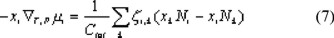
Equations (6) and (7) give the mass transfer description of the membrane separation process. To complete the model mass balances, a description of the solute distribution between the membrane and the liquid phase, a transition to absolute velocities, constraints and relationships to determine the friction coefficients are necessary.
Mass balances, partitioning of solutes, bootstraps and constraint relations
In the transport equations, the component velocities only appear as differences. For the calculation of absolute velocities additional relations are needed. These are provided by the mass balances at the permeate side of the membrane:
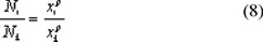
The following relation describes the partitioning of solutes:

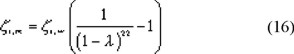
For cylindrical pores the distribution coefficient, Ki is given by Ferry [8]:
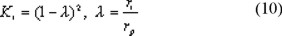
Partitioning of solvent causes an osmotic pressure jump at the membrane interface. In this work we only deal with very dilute solutions and in our experiments no decrease in fluxes is observed compared to clean water fluxes. Therefore, we ignore pressure jumps in our model and assume the pressure at the entrance and the exit of the membrane to be equal to the pressure at the feed and permeate side, respectively.
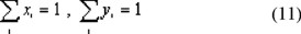
The model is completed by the constraint that the mole fractions have to add up to unity everywhere in the system.
Estimation of membrane friction coefficients
For a complete description of transport of molecules through narrow pores, more information is needed on the friction coefficients between permeating solutes and the membrane. We estimate these by the analogy with the reduction of falling velocities of macroscopic spheres in narrow tubes [9].
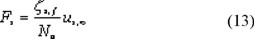
A Maxwell-Stefan form of the equation for the falling velocity of a single particle in a liquid, which is bound by a surface, is written as:
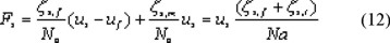
In a liquid, which is not bound, equation (12) reduces to:
From these equations, an expression for the friction factor between the particle and the surface, ft, can be found:
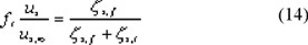
A relation for ft is presented by Lali [9], having measured falling velocities in narrow tubes, both in Newtonian and non-Newtonian liquids. The experimental data points on Newtonian liquids are not presented; instead a correlation is given, which is valid within 10 %. This correlation reads:
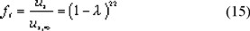
To find an expression for the friction of a large solute with a narrow membrane pore, assuming cylindrical pores, in equation (14) we replace zs,t and zs,f by zi,m and zi,w respectively. If we assume the solute-solvent friction coefficient zi,w to be the same in the membrane pores as in free liquid we obtain the solute-membrane friction coefficient, zi,m:
Other parameters
The friction coefficients of the solutes with water are determined from the radius of the solute with the Stokes-Einstein relation:

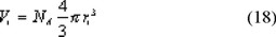
Friction between the different solutes is ignored as we work with very dilute solutions. The partial molar volume of the different components is calculated from the molecular radius according to:
Solving the model
For the ultrafiltration of a solution with n components the model consists of n equations of transport through the membrane, n-1 equations of transport through the boundary layer, which are needed if concentration polarization is taken into account, n-1 mass balances, n-1 equilibrium equations at both the upstream and the downstream side of the membrane, and a constraint relation at each point in the system. Both the boundary layer and the membrane layer are divided into 4 layers (with 5 grid points). The gradients in the Maxwell-Stefan equations are approached by a central difference scheme according to the approach of Wesselingh [10] and Krishna [7]. The complete set of equations is solved for the molar fluxes, local mole fractions and pressures, using the Newton-Raphson method [11]. All calculations are done ignoring the boundary layer except where explicitly mentioned. Model predictions are compared with experimental data, meanwhile optimizing the pore diameter as the only unknown parameter in the model, according to the Marquardt-Levenberg method [11]. The pore diameter, which gives the best comparison of model description and experimental results, is considered to be the mean pore diameter of the particular membrane type. With this pore diameter, the ratio of the effective pore length to the membrane porosity, τz/ε, should be varied such that the overall hydraulic permeability (εrp2/8τz) remains constant.
Experimental
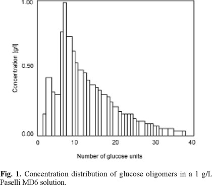
Solutions were prepared by dissolution of 1 g/L Paselli MD6 in reverse osmosis permeate, which was obtained from demineralized water. Paselli MD6 is a mixture of oligomers of glucose ranging from 2 to 40 units. The concentration distribution is presented in Fig. 1. The molecular radius of each oligomer was obtained from the formula given by Aimar et al. [12]:

The following membranes were tested: L1, L2, L3, L4. The methodology to prepared and characterized of this membrane were reported elsewhere [13,14]. The properties of these membranes are shown in Table 1.
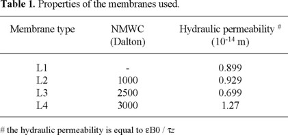
The hydraulic permeabilities of these membranes were determined from clean water flux experiments with new membranes, which underwent an initial compression procedure, and checked before each experiment with a control measurement at 10 bar. All control measurements agreed closely to the initial clean water flux experiments (within 5%) except for the NTR membrane. The hydraulic permeabilities of the L2 membrane varied as much as 30 % between experiments. Therefore, for this membrane the clean water flux measured just before the rejection experiment was used to obtain the hydraulic permeability.
Experiments were carried out at 20 °C and transmembrane pressure drops up to 15 bar. Cross flow velocity in all experiments was 0.9 m/s. Concentrations of the different oligosaccharides in both permeate and concentrate were determined by anion exchange chromatography according to the method of van Riel and Olieman [15]
Results
Fluxes
The fluxes, as measured during filtration of the oligosaccharide solutions, are shown in Fig. 2.
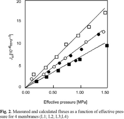
The experimental data are indicated by symbols, the predictions based upon clean water flux measurements by solid lines. They hardly differ, so we can safely assume that osmotic effects due to the rejection of the components are negligible.
Rejection curves
In Figure 3 the rejection of the different saccharides for an L2 membrane is shown as a function of permeate flux. The experimental results are indicated by symbols and the model predictions by the solid lines. In most cases the model gives a good prediction of the experimental data. Similar results are obtained with the L3 and the L4 membrane. In the case of the CA membrane it is difficult to give an exact determination of the pore diameter from the experiments, as the rejection data of only one oligosacharide are reliable, the others were very close to unity. This means that the diameters of the saccharides are too close to or even higher than the mean pore diameter.
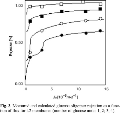
In the experiment with the more open L4 membrane, concentration polarization seems to play a role. Therefore, in the estimation of the pore diameter and the effective transport length, the boundary layer is taken into account. The pore diameter is 7% lower as compared to the fit omitting the boundary layer effects (Table 2). Concentration polarization plays no role in the other experiments.
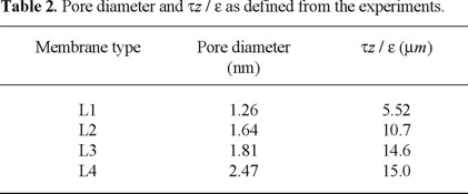
The pore diameters and the effective transport length, τΔz/ε, are presented in Table 2. We observe an increase in pore diameter, which corresponds with an increase of the NMWC-values. Our pore diameter for the L2 membrane is slightly higher than the one found by Wang et al. [16], while for the L4 membrane it is considerably different from their value of 1.6 nm. The latter is curious because of the good agreement of the hydraulic permeabilities. The effective transport lengths vary from 5.52 to 15 µm (or 17.3 µm, when ignoring concentration polarization). The effective transport lengths for the L2 and L4 membrane, given by Wang et al. [16], are dependent on the type of solute used. With neutral solutes they find values of 0.74 and 1.82 µm, respectively, while using NaCl the effective transport lengths are 3.44 and 5.99 µm, respectively. This difference in transport lengths between neutral solutes and salts found by Wang et al. [16], but also described by Nakao et al. [1] and Bowen et al. [3], is explained by the fact that the main pores of the membrane are interconnected by smaller pores, which are accessible for water but not for the larger solutes. Whereas the solutes are transported just through the main pores water can flow through the smaller pores and thus experience a longer transport length than the solutes. This mechanism could explain their difference in transport length found for different solutes. However, we successfully describe our experiments with only one parameter, i.e. the pore diameter. The ratio of effective pore length to membrane porosity, τz/ε, is determined from the hydraulic permeability. An independent fitting of the pore diameter and the effective transport length, as Nakao et al. [1], Bowen et al. [3] and Wang et al. [16] apply, is not necessary. An independent estimation of the effective transport length can be made from data of Coster et al. [17]. Coster [17] showed for a homogenous asymmetric polysulfone membrane that the separation layer has a thickness of about 200 nm. For a composite membrane this thickness generally is of the order of 1 or 2 µm. By impedance spectroscopy Coster et al. [17] determined porosities of skin layers of about 0.02 to 0.05. In a first approximation, taking ô equal to 1, the effective transport length should then be at least 4 µm. For this reason, the value of the L1 membrane, which is a homogeneous membrane, is in close accordance. In our opinion, the values of Wang et al. [16] seem to be too low. Our other membranes are composites and for this reason values in the range of 15 to 20 µm should be expected, in accordance with our results. The question might be raised why the transport length of the solvent is so much larger than for the solutes as most of the solvent will also seek the route with the lower resistance. An explanation for the observed difference can be found in the statistics underlying the parameter estimation. Nakao et al. [1], Bowen et al. [3] and Wang et al. [16] determine the quality of the fit on the residual sum of squares of the predicted and measured rejections only. In our case, however, the quality of the fit is established on the flux and the rejection simultaneously. An explanation for the difference in effective transport length between neutral solutes on the one hand and salts on the other is the omission of the electric potential induced solvent flow, which is opposite to the pressure induced flow. Ignoring this contribution will result in a larger transport length for salts as compared to neutral solutes. Good predictions of both the experimental flux and rejection can be obtained also, using the pore radius and effective transport length from our single experiment with an oligosaccharide mixture.
The method to determine pore sizes from experiments using a mixture of oligosaccharides is very useful. One simple experiment provides enough information to determine accurately the pore size of a particular membrane. Care should be taken in applying this method to very dense membranes as only one or a few saccharides are partially permeated through these membranes and rejections are above 0.9. This makes the determination of pore sizes for these dense membranes difficult.
Conclusions
Filtration of a dilute mixture of oligosaccharides is a successful experimental tool for the determination of mean pore diameter and thereby the separation characteristics of nanofiltration membranes. For very dense membranes, such as the CA membrane, the method can become inaccurate because most sugars are larger than the mean pore diameter. To characterize this class of membranes (NF with low NMWC or RO) a mixture of smaller solutes should be considered.
List of Symbols
B0: membrane permeability [m2]
C: concentration [mol.m-3]
D: diffusion coefficient [m2.s-1]
F: force on a component [N]
I: ionic strength [mol.m-3]
K: partition constant
Na: Avogadro number
Mw: molecular weight [g.mol-1]
N: molar flux [mol.m-2.s-1]
P: pressure [Pa]
r: radius [m]
R: gas constant [J.mol-1.K-1]
T: temperature [K]
u: diffusive volume flux [m.s-1]
V: partial molar volume [m3.mol-1]
í: viscous volume flux [m.s-1]
w: overall volume flux [m.s-1]
x: mole fraction in boundary layer
y: mole fraction in membrane
z: thickness of the membrane [m]
ε: porosity of membrane
η: viscosity [Pa.s]
λ: ratio of solute to pore radius
µ:chemical potential [J.mol-1]
Φ:electrical potential [V]
P: osmotic pressure jump at entrance or exit of membrane [Pa]
τ: tortuosity of membrane
ζ: friction coefficient [J.mol-1.m-2.s-1]
Subscripts
f: fluid
i, k: component index
m: membrane
p: pore
s: sphere
t: tube
tot: total
w: water
∞: unbound fluid
Superscripts
p: permeate
Acknowledgements
The authors are grateful for the support provided by VII Internal Awards, UABC-1401/2002.
References
1. Nakao, S.; Kimura, S. J. Chem. Eng. Japan 1981, 14, 32-38. [ Links ]
2. Hanemaaijer, J.H.; Robbertsen, T.; van den Boomgaard, Th.; Olieman, C.; Both, C.; Schmidt, P. Desalination, 1988, 68, 93-108. [ Links ]
3. Bowen, W.R.; Mohammad, A.W.; Hilal, N. J. Membrane Sci. 1997, 126, 91-105. [ Links ]
4. Vonk, P.; Noordman, T.R.; Schippers, D.; Tilstra, B.; Wesselingh, J.A. J. Membrane Sci. 1997, 130, 249-263. [ Links ]
5. Noordman, T.R.; Vonk, P.; Damen, V.H.; Brul, J.T.; Schaafsma, S.H.; de Haas, M.; Wesselingh, J.A. J. Membrane Sci. 1997, 135, 203-210. [ Links ]
6. Lightfoot, E.N. Transport Phenomena of Living Systems. John Wiley & Sons, New York, 1974. [ Links ]
7. Krishna, R. Chem. Eng. Comm. 1987, 59, 33-64. [ Links ]
8. Ferry, J.D. J. Gen. Physiol. 1936, 20, 95-104. [ Links ]
9. Lali, A.M.; Khare, A.S.; Joshi, J.B. Powder Technol. 1989, 57, 39-50. [ Links ]
10. Wesselingh, J.A.; Krishna, R. Mass Transfer, Ellis Horwood, London, 1990. [ Links ]
11. Press, W.H.; Flannery, B.P.; Teukolsky, S.A.; Vetterling, W.T. Numerical Recipes, Cambridge University Press, Cambridge 1987. [ Links ]
12. Aimar, P.; Meireles, M.; Sanchez, V. J. Membrane Sci. 1990, 54, 321-338. [ Links ]
13. Espinoza-Gómez, H.; Lin, S.W. Polymer Bulletin 2001, 3-4, 297-304. [ Links ]
14. Espinoza-Gómez, H.; Lin, S.W. Rev. Soc. Quím. Méx. 2003, 47, 53-57. [ Links ]
15. van Riel, J.; Olieman, C. Carbohydrate Research 1991, 215, 39-46. [ Links ]
16. Wang, X-L.; Tsuru, T.; Togoh, M.; Nakao, S-I.; Kimura, S. J. Chem. Eng. Japan 1995, 28, 186-192. [ Links ]
17. Coster, H.G.L.; Kim, K.J.; Dahlan, K.; Smith, J.R.; Fell, C.J.D. J. Membr. Sci. 1992, 66, 19-26. [ Links ]

