


 nueva página del texto (beta)
 Inglés (pdf)
 Artículo en XML
 Referencias del artículo
 Enviar artículo por email
 Citado por SciELO
  Similares en
SciELO
Similares en
SciELO 
 Permalink
1. Introduction
The number of patients, who have metallic implants such as mandibular plates, dental fillings, spinal cord fixation devices, surgical rods, stents, upper and lower extremity prostheses that require radiotherapy due to various malignancies, have been increasing in recent years. All the materials used in the implants have high atomic numbers and density; therefore, they tend to significantly affect target and normal tissue doses in the treatment region to be irradiated [1].
The variation of the dose changes, which is caused by the implants with high atomic number regarding factors like energy, material, geometry and thickness, have been revealed by the researchers via experimental and calculation methods [2-7]. In the literature, absorbed dose distributions have been evaluated by methods such as film dosimetry, different clinically used treatment planning system (TPS) algorithms, and Monte Carlo (MC) simulations. It has been observed that when the incident photon interacts with a high electron density material placed in water or tissue-equivalent medium, dose increase due to upstream backscattering and dose perturbation below the implant occur [8-12].
The implants with high atomic number reveal significant artifacts in reconstructed computed tomography (CT) images. Kovacs et al. studied metal artifact reduction techniques in order to determine the effects of radiotherapy on tumor description on CT images of phantoms containing various metal implants [13]. Byrnes et al. used different metal implant materials with known geometries to eliminate geometric uncertainties. They determined the errors in the dose calculation were caused by the Monaco MC algorithm from different electron density without the effects of incorrect contouring [14]. The dose distributions resulting from the effect of artifact and high electron density have been measured and calculated by researchers using MC methods [1, 15]. As a result, these implants cause difficulties to determine the con-tours of the object and calculating the correct dose distribution within the patient.
Delivering the prescribed dose to the patient with an accuracy of 3-4% is the key component of the achievement for the radiation therapy [16, 17]. Modern advances in radiotherapy have increased the accuracy of dose delivery [18]. The most important constituent of TPSs is accurate dose calculation [19]. Therefore, the use of MC calculation algorithm in commercial TPS has become widespread recently [14] since it is the most accurate approach in determining the dose released by ionizing radiation in a medium. This technique offers powerful numerical solutions to the highly complex problems. In radiotherapy, it has been proven mathematically that they are more advantageous than analytic algorithms in solving problems with many parameters, such as calculating the patient dose, specifically in regions with high density materials [20-23]. The usage of MC calculation algorithm provides the ability to calculate more reliable dose levels, especially in heterogeneous environments with high density implants to TPS [1, 24-28]. In addition to this, MC simulations allow to obtain accurate and detailed information in order to evaluate dose distributions in TPS [2].
Although TPS applies different correction factors to artifacts, it is very likely to make errors and misjudgments to determine the boundaries of implants by the observer. It is important to determine on what scale these errors would affect the dose calculations. Thus, planners and physicists are able to understand the uncertainties that exist and gain in dose delivery to target volumes and better sparing of organs at risk [14]. However, there has been no report on how metal implants should be contoured nor a study that would reveal the effects of certain errors in contouring on dose distribution. The aim of this study is to evaluate the dose change caused by deliberate contouring errors in the exact delineation of implants in the region of interest (ROI) near the implant by using both Monaco TPS and MC simulation with the Geant4 [29] toolkit.
2. Materials and methods
2.1. The physical and chemical properties of the materials
In order to eliminate the errors related to determination of density and boundaries due to the artifacts that high atomic number heterogeneity may reveal in CT images, implant materials with uniform geometry of known densities and dimensions were used. The implant materials were obtained from commercially available samples of titanium (Ti6Al4V) and cobalt (CoCrMo) alloys. The metal alloys with uniform cylindrical geometry were selected as 150 mm in height and 32 mm in diameter for Ti6Al4V and 29 mm for CoCrMo. Ti6Al4V alloy contains approximately 89.95% titanium, 5.80% aluminum, 3.92% vanadium and also trace amounts of hydrogen, carbon, nitrogen, oxygen, iron. CoCrMo alloy contains 65.35% cobalt, 27.2% chromium, 5.39% molybdenum and trace amounts of carbon, nitrogen, silicon, nickel, iron as well. The physical densities of Ti6Al4V and CoCrMo alloys are 4.43 g/cm3 and 8.30 g/cm3, respectively.
2.2. CT simulation
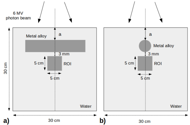
A water phantom with dimensions of 30 × 30 × 30 cm3 was setup in order to represent the geometry of the patient receiving external beam therapy. Ti6Al4V alloy was placed into the water horizontally at the depth of a = 3 cm from surface to skip the build up region (Fig. 1). Afterwards, the water phantom was CT-scanned on GE Healthcare Optima CT520 (GE Healthcare, Waukesha, WI, USA). CT scans of the phantom were acquired sequentially using a slice thickness of 1.25 mm at a peak tube voltage of 140 kV. The experimental phantom setup and imaging procedures were also repeated for the CoCrMo alloy placed at the depth of a = 3.5 cm from the water surface.
2.3. Monaco TPS dose calculations
The DICOM images of the water phantom were imported into the Elekta Monaco TPS (Version 5.11.02). TPS converts the Hounsfield units on the CT images into electron density values from the CT-to-ED table for the respective tube voltage. Then the Relative Electron Density (RED) value was assigned to each voxel. To assign the mass density (ρ) to the RED the following equation was used [30].
The mass density values are converted to RED values as Monaco TPS provides accurate calculations for density values in the range up to 3 g/cm3. As the mass density values rise above mentioned range, the accuracy of the dose accumulation decreases. Therefore, the RED value should be recalculated by using Eq. (1) [30]. The RED values for the Ti6Al4V and CoCrMo alloys used in this study were calculated as 3.92 and 7.21, respectively. Initially, the metal objects from both CT-scan data sets were contoured in Monaco TPS using known real dimensions. Then, the contours of the metal objects were contracted and expanded artificially by 2 mm, assumed to be the contouring misjudgment size, over their real dimensions in order to investigate the effect of errors in the demarcation process on the dose distribution in the ROI. Thus, each metal object was contoured in three different sizes as real, contracted, and expanded. Subsequently, recalculated RED values were assigned to the respective contours. The artifacts for real, contracted, and expanded metal implant volumes were contoured separately and the RED values were overridden as 1:0. In order to evaluate the effect of implant materials on dose distribution, the ROI was chosen as 5 × 5 × 5 cm3, located at 3 mm below the real Ti6Al4V and CoCrMo alloy volumes (Fig. 1). 6 MV photon energy beam for treatment plans were produced by the Elekta Synergy linear accelerator (Elekta, AB, Stockholm, Sweden). The field size was determined as 10 × 10 cm2 at a source to surface distance (SSD) of 100 cm. For the single field 200 MU was delivered to the phantom. In Monaco TPS voxel based MC algorithm the calculation properties were set to grid size 0.12 cm and statistical uncertainty per calculation 1%.
On the other hand, to obtain the depth dose (DD) values, the same experimental setup was applied in a virtual water phantom without alloy and calculated along the central beam axis in Monaco TPS.
2.4. Ion chamber measurement
The DD values of the 6 MV photon energy of the Elekta Synergy linear accelerator were measured with a PTW 0.125 cm3 semiflexion chamber (type 31010, PTW-Freiburg, Germany) and the field size 10 × 10 cm2 in the water phantom.
2.5. Geant4 Monte Carlo simulation
In this study, the head model of the Elekta Synergy linear accelerator equipped with the Elekta AgilityTM collimator was not simulated and the phase space data could not be obtained. At this point, the 6 MV photon energy spectrum data was taken from the study by Martins et al. [31] as the base. By using the reference 6 MV photon energy spectrum and the relevant source angle from the Elekta technical documents [32], the virtual water phantom (30 × 30 × 30 cm3) was irradiated with a field size of 10 ×10 cm2 at SSD of 100 cm in Geant4. A total of 109 particles were simulated, G4EmStandardPhysics option4 as a “standard” Geant4 electromagnetic physics list and 1 mm set cut parameters were used. The DD profiles were calculated from the surface of the water to 30 cm depth by using column-like scoring meshes along the central beam axis. The doses were recorded at different depths in water with 1 mm resolution. The calculated DD values were compared with the ion chamber measurement and Monaco TPS profile. Then, to be used in further simulations in this study, the energy spectrum data was modified by trial and error method to have the best match to the DD values.
The metal alloys were simulated with known composition and densities in order to evaluate the dose distributions in the ROI near Ti6Al4V and CoCrMo alloys. The alloys were individually placed in a virtual water phantom of 30×30×30 cm3 at depths of 3 cm and 3.5 cm for Ti6Al4V and CoCrMo, respectively. The ROI of 5 × 5 × 5 cm3 as the scorer were fixed at the position 3 mm below the real Ti6Al4V and CoCrMo alloy volumes. By using the 6 MV energy spectrum data the water phantom was simulated with similar parameters in the DD calculation in the ROI. Since the chosen ROI remained in the region where the dose profiles (inplane-crossplane) of 10×10 cm2 field size were nearly flat on the plateau, only the modified spectrum verified by the DD profiles was used for all the simulations in the absent of phase space. The simulation processes were repeated individually for real, contracted and expanded configurations of the alloys.
3. Results
By using the energy spectrum (Fig. 2), the DD values along the central axis at SSD of 100 cm with a field size of 10 × 10 cm2 was calculated with Geant4. Then, the DD values were normalized with the maximum value of Monaco TPS. Thus, the three DD curves of Geant4, Monaco TPS and ion chamber measurement have been made suitable for comparison with each other. The 6 MV photon beam DD values for Elekta Synergy linear accelerator are fairly similar, as it is shown in Fig. 3 and the difference between them is below 1%. The detailed inset image also shows small differences between the DD values. According to the reports of the International Commission on Radiation Units and Measurements 42, the dose calculation algorithms used in TPS should aim at a maximum deviation of 2% from accuracy in regions with low dose changes [33].
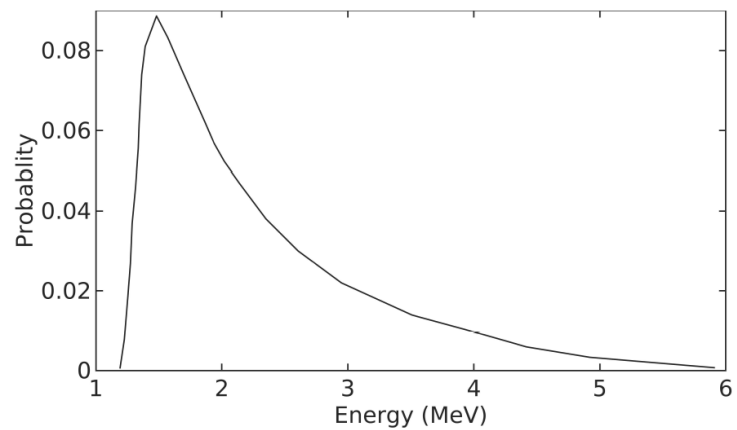
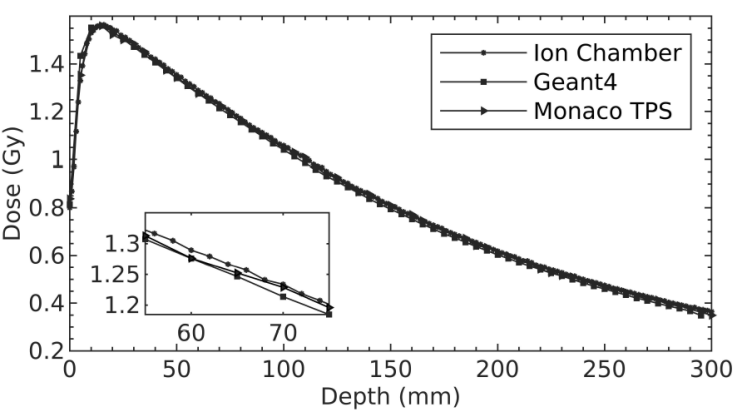
Figure 3 The normalized DD curves obtained by Geant4, Monaco TPS and ion chamber measurement for 6 MV photon energy. Inset: Close-up view between the depth of 55-75 mm.
The dose distributions along the central axis with real, contracted and expanded contouring of the alloys were evaluated in ROIs for Geant4 and Monaco TPS. As seen in Fig. 4, the local isodose values among the alloys vary up to 15%. When all the isodose graphics were considered, it was observed that each graph was symmetrical along the central beam axis. Moreover, the dose patterns for Geant4 and Monaco TPS were compatible with each other.
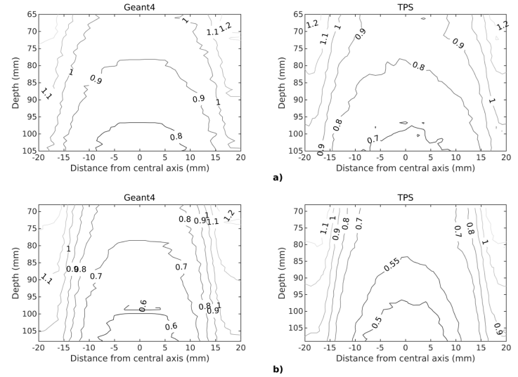
Figure 4 The isodose graphics of a) Ti6Al4V b) CoCrMo alloys shown here only contoured to their real dimensions along the central beam axis.
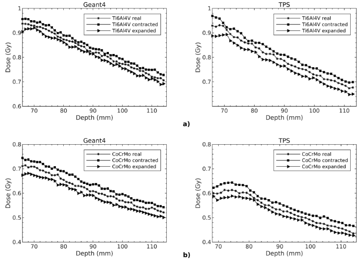
The dose changes with respect to depth in ROIs were evaluated for three different contours. As shown in Fig.4, the results are consistent with each other for Geant4 and Monaco TPS. The dose values are in decreasing order of contracted, real and expanded contours. Also seen that the dose decrease is greater for CoCrMo than Ti6Al4V in all ROIs.
The dose calculations were performed in Geant4 by using the modified X-ray energy spectrum and dose values were obtained from TPS. The mean dose differences in three different size ROIs (3 × 3 × 3 cm3 ; 4 × 4 × 4 cm3 ; 5 × 5 × 5 cm3) were calculated to observe the contouring effect. Table I shows the percentage mean dose differences in ROIs, depending on the different contouring sizes of Ti6Al4V and CoCrMo alloys for both Geant4 and Monaco TPS. The differences were found to be negative for real minus contracted (real - contracted) contours and positive for real minus expanded (real - expanded) contours. The greatest mean dose difference observed in 3 × 3 × 3 cm3. In general, the dose differences between the Geant4 and Monaco TPS calculations decrease as ROI size increases. Due to the different contouring the mean dose differences ranges from ±2.4% to ±5.2% and ±3.9% to ±8.0% for Ti6Al4V and CoCrMo alloys, respectively.
Table I The percentage mean dose differences due to contour sizes (±2 mm).
| Ti6Al4V alloy | CoCrMo alloy | |||||||
|---|---|---|---|---|---|---|---|---|
| Mean dose differences % | Mean dose differences % | |||||||
| ROI size (cm 3) | Real-Contracted | Real-Expanded | Real-Contracted | Real-Expanded | ||||
| Geant4 | TPS | Geant4 | TPS | Geant4 | TPS | Geant4 | TPS | |
| 3×3×3 | -3.1 | -5.2 | 3.4 | 5.0 | -6.5 | -8.0 | 6.1 | 7.1 |
| 4×4×4 | -2.8 | -4.4 | 2.8 | 4.4 | -4.8 | -6.1 | 5.0 | 5.7 |
| 5×5×5 | -2.4 | -3.4 | 2.4 | 3.8 | -3.9 | -5.1 | 4.0 | 4.5 |
4. Discussion
The DD values obtained from Geant4 simulation were well-matched to ion chamber measurements and Monaco TPS calculations. However, despite using the estimated energy spectrum, a certain dose difference occurred between Geant4 and Monaco TPS in all contouring configurations. This is similar to the results of the study in which the dose discrepancies of up to 9.5% were attained in the shadow of inhomogeneity [34]. In addition, it has been shown in previous studies that the differences between measurements at a certain depth and TPS algorithms cause dose uncertainties of 5 - 23% [1, 14, 24-28]. However, a better match between measurements and simulations with full linear accelerator head simulation could be achieved if all the details were available. While the main method is still the full modeling of the linear accelerator head, using a modified energy spectrum for MC simulations where geometric details, verified phase space and energy spectrum were not available offers an alternative [31].
The dose distributions in contouring of alloys in different sizes were analyzed with the isodose and the DD graphs in the ROIs. While the isodose values of Geant4 and Monaco TPS created by the beams passing through the edges of the irradiated metal alloys are in good agreement, the certain differences have been found in the regions under the shadow of the metal alloys. Because, distortion occurs in the absorbed dose distribution due to the attenuation of the beam and the interactions at the tissue-metal interface when the incident photon passes through the metallic implant [1]. This effect decreases when the metal alloys are contoured as contracted and increases as expanded. Compton scattering is the dominant type of interaction that occurs between MeV photons and high-density heterogeneities. Independent of effective atomic number (Z eff), the number of these interactions increases with electron density [35]. Therefore, the entrance dose of ROI which depend on the density of the alloy was higher for Ti6Al4V alloy compared to CoCrMo alloy for both Geant4 and Monaco TPS.
The percentage mean dose differences in Table I show that the CoCrMo alloy absorbed more energy and created more heterogeneous dose distribution in the closer region due to the higher bulk and electron density [36]. Hence, the percentage mean dose differences of CoCrMo were greater than of Ti6Al4V among all contours. To avoid the edge effect of the beam, small volume ROIs such as 3× 3× 3 cm3 ; 4 × 4× 4 cm3 ; 5 × 5 × 5 cm3 were chosen and placed at a certain distance from the alloys along the central beam axis. The percentage mean dose differences calculated in 3 × 3 × 3 cm3 ROIs were the highest in all contouring configurations. Since the ROIs were closer to metal alloys, the scattering contribution from them is higher to the dose. Accordingly, the dose differences between Geant4 simulation and Monaco TPS calculations decreased as the ROI volume increased and as the metal alloys moved away. In the experimental study of Byrnes et al., the percentage of mean dose differences between the TPS calculations and measured in the small field size in the dose shadow of blocks with a total metal thickness of 3 cm were evaluated. The dose differences calculated by exact contouring increased as the density of the material increased. Thus, the results are compatible without exact delineation of implants [14].
As a result, the limitations in determining the contours of metal alloys that cause artifacts in CT images led to errors in dose calculations. This study shows that ±2 mm error in determining the boundaries of metal alloys caused up to ±8% differences in the dose calculations in a close region, depending on the density of the material consisting of uniform cylindrical geometry. If the existing material does not have a uniform geometry, the borders will be contoured as contracted in some cases and expanded in some other. In this case, the dose calculation error would be higher in a region close to the alloy.
5. Conclusion
The dose distortions in radiotherapy due to artifacts caused by high atomic number materials have been calculated with TPS and compared with MC simulations to evaluate these dose changes in a detailed and reliable way. It has been found that the mistakes made in contouring high density materials cause significant dose differences. Even these errors of a few millimeters in contouring can lead to increased doses of organs at risk in the treatment region or lower doses in the target volume. This will become increasingly important, especially in situations where the overlap between target volume and metal implants is large. Thus, it can have a significant negative impact on patient outcomes. This study emphasized the importance of the effect of implant composition and contouring size on dose distributions in a region close to the material. Thus, it will eliminate one aspect of the uncertainty in the planning process. Therefore, materials with high atomic numbers in the patient’s CT images should be contoured very carefully and their mass density values should be assigned to TPS [11]. In further studies, it is desired to evaluate the dose differences in non-uniform geometries in regions close to high density materials.

