


 nueva página del texto (beta)
 Inglés (pdf)
 Artículo en XML
 Referencias del artículo
 Enviar artículo por email
 Citado por SciELO
  Similares en
SciELO
Similares en
SciELO 
 Permalink
Nomenclature
| C | Heat capacity (J/K) | N | Nth cycle | |
| c | Specific heat capacity (J/kg·K) | Acronyms | ||
| Dm | Energy density (kJ/kg) | CSP | Concentrating solar power | |
| Dv | Volumetric energy density (GJ/m3) | DNI | Direct normal irradiance (kWh/m2/year) | |
| E | Thermal energy (J) | EDS | Energy Dispersive Spectroscopy | |
| g | Gas | GHGs | Greehouse gases | |
| G | Gibbs energy (free energy) (kJ) | HoSIER | High Radiative Flux Solar Furnace from IER-UNAM | |
| H | Enthalpy (kJ) | HT | High temperature | |
| K | Equilibrium constant | HTF | Heat transfer fluid | |
| Wh | Watt-hora | IER | Renewable Energy Institute | |
| m | Mass (kg). | IIM | Materials Research Institute | |
| p | Pressure (Pa) | IRENA | International renewable energy agency | |
| ρ | Mass density (kg/m3) | LACYQS | The National Laboratory for Solar Concentration Systems and Solar Chemistry | |
| R | Gas constant (8.314 J/mol⋅K) | LCOE | Levelized cost of energy | |
| S | Entropy (kJ/K) | LHS | Latent heat storage | |
| s | Solid | LTQSUAM | Solar thermochemistry laboratory at Metropolitan Autonomous University | |
| T | Temperature (K) | PCM | Phase change material | |
| T* | Turning temperature | PV | Photovoltaic | |
| Tm | Melting temperature | SEM | Scanning electron microscopy | |
| To | Reference temperature | SHS | Sensible heat storage | |
| X eff | Effective conversion | SOFC | Solid Oxide Fuel Cell | |
| Greek letters and subscripts | TES | Thermal storage system | ||
| ΔH R | Reaction enthalpy (kJ/kg) | TGA | Thermogravimetric analyzer | |
| λ | Latent heat (kJ/kg) | TRL | Technology Readiness Levels | |
| ξ | Reaction yield | TQ | Thermochemical | |
| δ | Stoichiometric constant | UNAM | National Autonomous University of Mexico | |
| cal | Calcination | USD | United States dollar | |
| car | Carbonation | XRD | X-Ray Diffraction |
Introduction
The Solar Thermochemistry Laboratory was established at UAM-I in 1982. It is a leading and pioneer laboratory in the field of solar thermochemistry in Latin America. It has been recognized as a school of excellence in this study area for over forty years. Graduates from the laboratory have gone on to create their laboratories at other institutions, and we have been working to establish a research network to promote research on the use of concentrated solar energy for chemical processes. The primary focus of this research is on thermal energy storage systems, producing clean energy vectors, and developing industrial chemical processes at medium and high temperatures using concentrated solar energy, such as oil coke gasification or cement or ceramics production. The research potentially benefits using solar energy at medium and high temperatures, reducing carbon emissions, and providing cleaner and more constant energy sources that help mitigate global heating.
Climate change is currently a priority and a critical situation that demands immediate resolution and political will. It is a global concern, and its mitigation should be the highest priority for all countries. Moreover, it poses a significant threat to global food security, sustainable development, and poverty eradication. The greenhouse gases (GHGs) produced by human activity are the primary driver of climate change [1]. Thermal and Power generation contributes substantial CO2 emissions and other gases to the environment, necessitating the exploration of new technologies to mitigate them [2]. Renewable energy sources like wind and solar power have been in used for years, offering a clean and sustainable way to generate electricity. However, they also present a challenge: their intermittent and unpredictable nature leads to fluctuations in the transmission and distribution of electrical energy. This is particularly true for solar energy, which exhibits day-night cyclicality, resulting in low plant factors.
However, despite these challenges, solar energy has many applications that make it a valuable option for energy production. Photovoltaic systems (PVS) solar energy can be directly converted into electrical energy. Alternatively, concentrated solar power systems can convert solar energy into mechanical energy, which can then be used to generate electricity. Solar energy can also produce heat for various applications, such as passive heating of buildings, active heating of water or air, cooling, or industrial processes [3,4]. Additionally, it can be used to produce solar fuels such as hydrogen, syngas, and kerosene [5].
By harnessing solar energy's power, we can reduce our reliance on non-renewable sources and help create a more sustainable future. While solar energy may have its challenges, it offers many benefits that make it a valuable option for energy production. Solar thermal energy is an important renewable, abundant, and clean source. It is a resource that can be exploited to help replace fossil fuels. There are currently different technologies to make use of this renewable resource at its different levels of operating temperatures. In these technologies, evacuated tube collectors, collector heat pipes, and compound parabolic collectors are the most common for low-temperature flat plate collectors. The most currently used for high temperatures are parabolic troughs, followed by concentrated solar towers, and Fresnel and dish collectors represent a minor fraction.
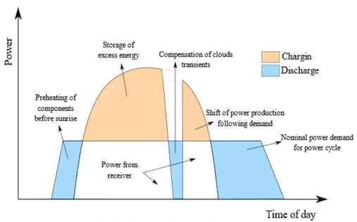
Scientific and technological research is essential to address the problem of intermittency in solar energy and promote its use as a clean energy source to reduce the impact of global warming. One of the most promising mechanisms to achieve this goal is to store thermal energy and then release it to an optimal temperature for a given application. Although concentrating solar systems for solar power generation have been extensively tested in industrial thermal energy applications, they still suffer from low plant capacity factors, which limits their efficiency. Several solar thermal energy storage systems have been proposed based on the sensible heat of substances that can overcome the disadvantage of the intermittence of solar energy. Fig. 1 illustrates the importance of energy storage in meeting a specific power requirement most feasibly. The loading and unloading operation of the storage is observed throughout the day. The discharge happens when the solar resource is insufficient or at night, while the load occurs when there is a surplus or the demand decreases [6-8].
Utilizing solar thermal energy in industrial processes is vital to achieving sustainable and environmentally responsible industrial operations. This renewable energy source harnesses the sun's abundant and inexhaustible heat to meet the substantial energy demands of various industrial sectors. As the global community intensifies its focus on reducing greenhouse gas emissions and transitioning towards cleaner energy sources, solar thermal technology emerges as a promising solution with significant potential for industrial applications. Scientific research has extensively explored the technical feasibility, economic viability, and environmental benefits of integrating solar thermal energy into industrial processes. IRENA (2012) [9] has highlighted the immense potential of solar thermal systems to provide process heat at high temperatures required by industries while reducing reliance on fossil fuels and mitigating carbon emissions. Examples of possible uses include steam generation, drying processes, and chemical reactions such as calcination processes in the cement industry.
Solar thermal technology encompasses various solar collectors and concentrating systems, each tailored to meet specific industrial heat requirements. Research by Romero et al. (2019) [10] has delved into the design, optimization, and performance analysis of various solar thermal collectors, including parabolic troughs, solar towers, and dish collectors, elucidating their efficacy in industrial heat generation. Furthermore, integrating thermal energy storage systems with solar thermal plants has garnered significant attention in scientific literature. Frazzica and Cabeza (2019) [11] and Palacios et al. (2020) [12] have explored advanced thermal storage materials and techniques, enabling the efficient storage and utilization of solar heat for industrial processes, thereby enhancing system reliability and flexibility.
CSP is becoming competitive compared to other renewable energy systems, even with conventional fossil fuels. Solar thermal plants using central tower technology operate worldwide under two different schemes. The first scheme uses molten salts as a heat transfer fluid and energy storage system coupled to a steam turbine. The second scheme is like the first one but uses a gas turbine [12-14]. These operating schemes need high efficiencies to compete in the electricity market. Therefore, there is an opportunity to propose new power cycles and forms of thermal energy storage that can generate electricity at a lower cost per kWh. These new arrangements are expected to increase the global efficiency of solar-electrical power and the capacity factor, which is the number of hours of operation per year. Fig. 2 shows how the number of storage hours affects the capacity factor for different solar concentration technologies. The graph illustrates the importance of having a high-efficiency storage system for these technologies. For instance, when it comes to central tower technology, without storage, the average plant capacity factor is around 30%. However, when the storage capacity is more than 10 hours, the plant capacity factor significantly increases to 77%. This means that with a more efficient storage system, the technology can become more competitive compared to other technologies. Nonetheless, there is still a need to improve thermal storage efficiency.
There are 58 solar thermal power plants in operation, with the vast majority utilizing parabolic trough technology. While some plants use Fresnel and central tower technology, most use parabolic troughs. Furthermore, 38 solar thermal plants are currently under construction and mostly use parabolic trough technology. There are plans for additional plants in the future. It is critical to note that the focus is on lowering the levelized cost of energy (LCOE) to become more competitive with other clean technologies such as PV, wind, geothermal, and micro-hydro [15].
Various alternatives for energy storage are being researched to ensure availability during periods of insufficient solar resources, such as at night. The first central tower solar thermal power plants utilizing supercritical CO2 (sCO2) as a working fluid are anticipated to be operational by 2030. Simultaneously, research into new solar thermal energy storage solutions will continue.
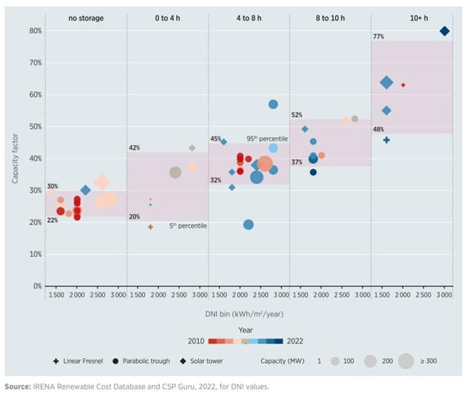
Fig. 2 Capacity factor trends for CSP technologies by direct normal irradiance and storage duration, 2010-2022. From [15].
Solar thermal energy storage systems can be categorized into three distinct technologies: sensible heat, latent heat, and chemical reaction heat. To gain a better understanding of each of these systems, the following section provides a brief explanation of each.
This paper will provide an overview of our laboratory's latest work results. The first part presents a brief overview of the current state of thermal energy storage (TES), exploring its applications, plant technologies, materials, and state of research. Section 2 discusses various types of energy storage classified by storage duration, heat exchange type, and storage time interval, including a detailed analysis of the different technologies available for sensible, latent, and thermochemical energy storage. Section 3 presents the thermodynamics of reactions. Section 4 explains the materials and methods employed in the laboratory experiments studied in recent years. This section covers the materials selected for studying thermochemical storage, the methods of characterization and analysis, and the calculation of storage density and effective conversion. Lastly, section 5 outlines an outlook and conclusions.
Thermal Energy Storage
The storage of solar energy has been a great challenge, allowing for rapid development in materials and technologies that cushion daily variations in solar flux. However, these developments lead to new challenges in developing cost-effective materials and components.
For more than four decades, the storage of solar energy has been a significant concern for the technological advancement of solar power systems. Over the years, several systems have been proposed to boost the efficiency of power plants [16-22] and other applications at lower temperatures.
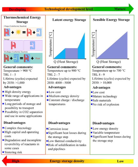
There are three forms of thermal energy storage: sensible, latent, and thermochemical heat, as illustrated in Fig. 3, which contains relevant information from the following references [23-27]. Among these, sensible heat is the most developed technology, but its drawback is its low energy storage density and temperature, which are not constant. Latent heat, on the other hand, is less developed but has a slightly higher energy storage density. The phase change energy involved in this process could be very attractive; deep research to find the material that covers the needed at a lower price is necessary. The most attractive solution, however, is chemical energy storage, which is currently under development.
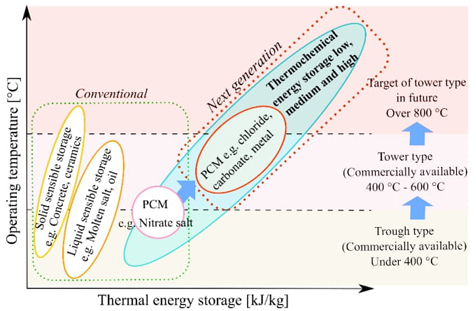
The choice of thermal energy storage method depends on the operating temperature and the amount of thermal energy desired to be stored. Fig. 4 gives an idea of the applications of the three principles described. Currently, new materials and methods are being investigated to improve their performance and stability.
For energy storage, the molten salt FLiNaK (46.5 % LiF, 11.5 % NaF, and 42 % KF) for sensible heat storage can reach temperatures up to 1003 K [21,28,29]. This temperature is compatible with the gas turbine inlet temperature, which typically operates between 973 and 1273 K and is more efficient [30-32]. According to F. Crespi [33], the best-performing configuration is the Brayton cycle with partial cooling. However, such systems require an energy storage system with higher temperature and storage capacity per unit mass. Thermochemical storage has a higher energy density than sensible and latent heat energy storage, as shown in Table 1. Furthermore, it allows for a prolonged storage period, increasing the plant capacity factor and improving the hours of operation per year of a solar tower power plant.
Table 1 Properties of different thermal storage medium. Adapted from [34-38].
| Storage technologies | Sensible heat storage | Latent heat storage | Thermochemical heat storage |
|---|---|---|---|
| Storage shape | Thermal | Thermal | Thermochemical |
| Efficiency (%) | 50 - 90 | 75 - 90 | 75 - 100 |
| Initial capital cost (USD/kW) (2020) | 3400 - 4500 | 6000 - 15000 | 1000 - 3000 |
| Energy cost (USD/kWh) (2020) | 0.1 - 13 | 10 - 56 | 8 - 100 |
| Energy storage density (kWh/m3) | 25 | 100 | ~500 |
| Energy storage density (kWh/kg) | ~0.02 - 0.03 | ~0.05 - 1 | ~0.5 - 1 |
| Storage capacity (MW) | 0.1- 300 | 0.1- 300 | 0.1 - 300 |
Sensible energy storage materials and systems
Sensible heat storage takes advantage of the thermophysical properties of materials, particularly the heat capacity of solids and liquids Although gases make it possible to store sensible heat, their storage capacity per unit volume is very small, so they are not considered in most applications. Sensible heat storage involves storing thermal energy by raising the temperature of a substance [39]. The total change of the internal energy of a material during a charging and discharging process is related to its storage capacity. The amount of thermal energy stored is a function of the specific heat capacity of the substance, the change in temperature, and the mass density, according to the relation:
Solids have a greater thermal storage capacity than liquids; however, the latter can flow through pipes. The simplest example of sensible heat storage is buildings that are heated during the day due to solar radiation incident on their wall surfaces. The stored heat is released during the night to heat the interior of the building. Sensible heat can also be stored in sand and rocks. These systems are highly sustainable if the heat is taken from solar energy. Table 2 presents the thermophysical properties of solids used for sensible heat storage.
Sensible heat storage in liquids is one of the most common for low-temperature applications; for example, at temperatures below 373 K, water is one of the most used fluids due to its high specific heat capacity (4.182 J/g K). Water has several advantages, including its non-toxicity. And non-flammable nature, high availability, and the potential to eliminate the need for heat exchangers when used as a working fluid in solar collectors. Liquid metals such as aluminum, copper, and lead can be used in sensible heat storage [40-42]. Its advantages are high thermal conductivity and density, but its cost is usually relatively high compared to other materials used for TES.
Table 2 Thermophysical properties of solids used in sensible heat storage. Data from [43].
| Material | Density (kg/m3) | Specific heat capacity (J/kg K) | Volumetric heat capacity (x106 J/m3K) |
|---|---|---|---|
| Alumina spheres | 3953 | 1157 | 4.574 |
| Aluminium | 2710 | 896 | 2.428 |
| Basalt | 3000 | 920 | 2.76 |
| Brick | 1800 | 837 | 1.507 |
| Clay | 1458 | 879 | 1.282 |
| Concrete | 200 | 880 | 0.176 |
| Gabbro | 2911 | 643 | 1.872 |
| Glass | 2710 | 837 | 2.268 |
| Gravelly earth | 2050 | 1840 | 3.772 |
| HT ceramic | 3500 | 866 | 3.031 |
| HT concrete | 2750 | 916 | 2.519 |
| Iron | 7900 | 452 | 3.571 |
| Magnetite | 5177 | 752 | 3.893 |
| Refractory bricks | 3000 | 1150 | 3.45 |
| Sandstone | 2200 | 712 | 1.566 |
| Slags | 3770 | 912 | 3.438 |
| Steel | 7840 | 465 | 3.646 |
| Vitrified asbestos | 3120 | 1034 | 3.226 |
| Water | 988 | 4182 | 4.132 |
| Wood | 700 | 2390 | 1.673 |
| Zirconia | 5999 | 597 | 3.581 |
There are various alternatives for temperatures above 373 K but below 573 K, including thermal oils (synthetic, mineral, and organic), molten salts, and liquid metals. Some oils, such as Dowtherm and Therminol, are suitable for temperatures between 373 and 573 K. These can degrade over time and pose flammability problems. Concentrating solar plants use thermal oils, including vegetable oils. Synthetic oils are generally preferred over traditional mineral oils because they have better thermophysical properties (lower viscosity, higher thermal conductivity, and higher heat capacity) [40-42]. Barrasso et al. (2023) [44] present the thermophysical properties of some of the liquids proposed to store heat. Thermal oils have the advantage of a low vapor pressure compared to low-viscosity fluids. Their handling is relatively simple, and their storage is carried out in tanks at lower pressure. Table 3 shows the thermophysical properties of oils used as thermal storage media.
When the temperature exceeds the limits of organic thermal oils, molten salts are used to store heat at temperatures of up to 823 K. Eutectic mixtures have been studied for sensible heat and latent heat storage for over forty years. Eutectic mixtures include the ternary mixture of salts, like Hitec, which is a eutectic mixture of water-soluble, inorganic salts of potassium nitrate, sodium nitrite, and sodium nitrate (53 % KNO3, 7 % NaNO3, and 40 % NaNO2), whose melting temperature is 415 K and used up to 727 K. The binary mixture of salts is widely used (60 % NaNO3 and 40 % KNO3) [44,45]. Sodium hydroxide, with a melting temperature of 593 K, is usable up to 1073 K, highly corrosive, and difficult to contain at high temperatures; it is the second most used molten salt [12].
Table 3 Properties of liquids oils and molten salts to sensible Heat Storage capacity. Data from [12].
| Substance | Fluid | Melting temperature [K] | Temperature range [K] | Density [kg/m3] | Heat Capacity [J/kg K] | Comments |
|---|---|---|---|---|---|---|
| Calorie HT43 | Oil | - | 283-588 | 888 | 2300 | Non-oxidizing at high temperatures |
| Therminol 55 | Oil | - | 291-588 | 672 | 2400 | Density at 573 K |
| Therminol 66 | Oil | - | 282-618 | 770 | 2100 | Density at 618 K |
| Dowtherm A | Oil | 285 | 285-533 | 897 - 1043 | 2200 | Eutectic mixture |
| Hitec | Molten salt | 415 | 423-863 | - | 1550 | -- |
| Draw salt (50% NaNO3-50% KNO3) | Molten salt | 779 | 523-863 | - | 1550 | -- |
| Sodium | Liquid metal | 593 | 398-1033 | 927 | 1300 | Reacts violently with water and oxygen |
Latent energy storage materials and systems
A latent storage system (LTES) consists of a substance capable of undergoing a phase transition in the considered temperature range, and the supplied heat is stored as latent heat. The thermal energy is used to break the molecular bonds and allow the change of state (fusion-vaporization) without temperature variation: it is an endothermic process that accumulates heat, making it available later. The stored thermal energy is a function of the mass and of the latent heat of fusion of the substance, according to the relation:
where E = Stored energy, kJ; m = mass of material, kg; ( =Latent heat, kJ/kg. To reach the melting temperature, a specific amount of sensible heat must be supplied. This energy will only be recovered when the material cools to its initial temperature. However, in a continuous system, this energy remains stored and unused. Some sensible heat is supplied to superheat the material after it has slightly melted. The equation is as follows:
where c 1 and c 2 are the specific heat capacities at the initial and final phases, respectively, T 1 , T 2 , and Tm refer to the initial, melting, and final temperatures, respectively. Like sensible heat storage systems, latent heat storage presents unavoidable energy losses, even if the containers are properly thermally insulated.
LHS systems are classified based on the type of phase change process involved, such as solid-solid, solid-liquid, solid-gas, and liquid-gas. However, the latter two transformations are not commonly used due to the complexities associated with volume changes, and solid-solid transformations have little associated heat. So, the most common option is solid-liquid transitions due to their high heat storage density and the minimal volume changes necessary for effective storage [46].
Phase change materials used to store heat in solid-liquid transitions can be classified into organic, inorganic, and eutectic materials, as reported in the references [46-48]. Fig. 5 shows the thermodynamic characteristics of thermal storage and some examples of these materials, and it contains relevant information from the following references [48-53].
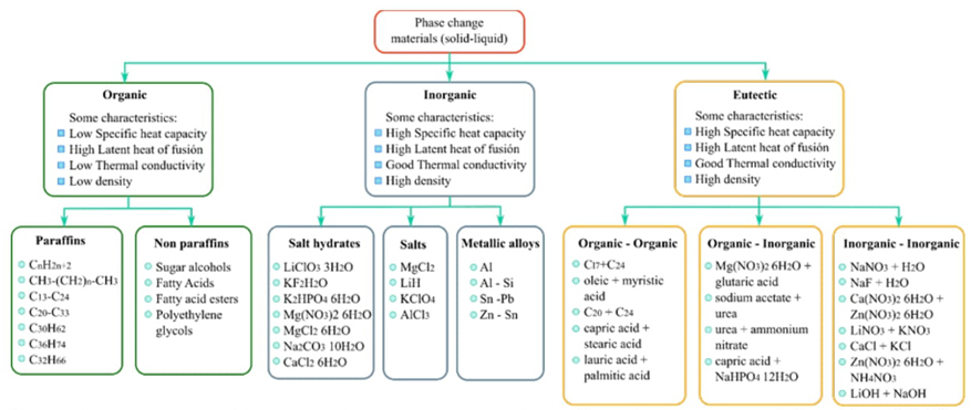
Fig. 5 Phase change materials characteristics and some examples as thermal energy storage. Adapted from [48-53].
Table 4 presents the melting temperature and latent heat of some of the most common latent heat storage media materials.
Eutectic refers to a mixture whose melting (solidification) point is lower than that corresponding to each component in its pure state. Eutectic mixtures have high stability in the liquid state, and their constituents are insoluble in the solid state. Eutectic mixtures can combine inorganic-inorganic, inorganic-organic, or organic-organic compounds. Table 5 shows the eutectic mixtures commonly used as sensible heat storage media.
Table 4 Melting temperature and latent heat of some of the most common materials used as latent heat storage media. Data from [52-54].
| Category | Material | Melting temperature [K] | Latent heat [kJ/kg] |
|---|---|---|---|
| Organic | Bees Wax | 334.8 | 177 |
| Benzoic acid | 394.7 | 142.8 | |
| Cetyl alcohol | 322.3 | 141 | |
| Dyphenyl amine | 325.9 | 107 | |
| Glycerin | 290.9 | 198.7 | |
| Hydrophosporic acid | 328 | 213 | |
| Isomalt | 420 | 275 | |
| Pentaerythritol | 460 | 255 | |
| Phenol | 314 | 120 | |
| Polyethylene glycol 35000 | 341.7 | 166.9 | |
| Polyethylene glycol 600 | 285.5 | 129.1 | |
| Quinone | 388 | 171 | |
| Stearic acid | 342 | 209 | |
| Inorganic | Ca(NO3)2 | 834 | - |
| CaCl2 6H2O | 302 | 190.8 | |
| CoSO4 7H2O | 313.7 | 170 | |
| KNO3 | 606 | 266 | |
| LiClO3 3H2O | 281 | 155 - 253 | |
| LiNO3 | 526 | - | |
| LiNO3 2H2O | 303 | 296 | |
| LiNO3 3H2O | 293 | 189 | |
| MgCl2 | 987 | 452 | |
| MgCl2 6H2O | 390 | 167 | |
| Na(NO3)2 6H2O | 330 | 169 | |
| Na2 CO3 | 1127 | 275.7 | |
| NaNO3 | 580 | 172 | |
| NaOH H2O | 337.3 | 273 |
Table 5 Eutectic mixtures commonly used as sensible heat storage media. Data from [55]
| Salt mixture | Latent heat [kJ/kg] |
|---|---|
| 20Li2CO3+60Na2CO3+20K2CO3 (wt%) | 279 |
| 44 Li2CO3 + 56 Na2CO3 (wt%) | 370 |
| 52.1 NaCl + 47.9 CaCl2 (mol%) | 155.6 |
| 25 KCl + 29 NaCl + 66 CaCl2 (wt%) | 245 |
| 48 NaCl + 52 MgCl2 (wt%) | 351 |
| 24 KCl + 47 BaCl2 + 29 CaCl2 (wt%) | 219 |
| 80.5 LiF + 29.5 CaF2 (wt%) | 820 |
| 33.5 NaF + 66.5 NaCl (mol%) | 533.8 |
| 53.3 NaCl + 46.7 Na2SO4 (mol%) | 232.3 |
The materials that store latent heat must have specific thermophysical and chemical properties to perform their function adequately. Thermophysical properties: melting temperature in the operating range, high latent heat of phase transition per unit volume, high thermal conductivity of both phases, small volume change in phase transformation, low vapor pressure at operating temperature, high nucleation rate, and adequate crystallization rate. Chemical properties: long-term chemical stability, fully reversible solidification-melting cycle, compatibility with container construction materials, non-toxic, non-flammable and non-explosive to ensure safety, various authors have reported these criteria [53,56].
Most phase change materials do not fully meet those criteria. However, recent advances in the design of new materials for energy storage, including nanomaterials, have opened new possibilities for improving material performance [53].
Thermochemical energy storage; materials and systems
Scientific literature extensively discusses reversible chemical reactions for thermochemical energy storage, and some of these references are [8,57-62]. These reversible reactions allow the accumulation of substantial energy in small amounts of matter that can be stored at room temperature for long periods and then released at high temperatures. This heat storage method is based on bidirectional endothermic and exothermic reactions. In the endothermic reaction, the thermal energy supplied to the system is stored in the chemical bonds of the molecules, while the exothermic reaction releases the stored thermal energy. The amount of thermal energy stored depends on the reaction enthalpy of the material, and the amount of matter involved in the process, as well as the yield of the reaction, according to the following expression:
An excellent example of a reversible reaction to store thermochemical energy is the dissociation of a metal sulfate [63] (MSO4) see Eq. 5. The sulfate dissociation reaction is carried out at high temperature in a reactor with an adapted solar concentration system that provides the heat necessary to carry out the reaction. On the other hand, the product recombination reaction is exothermic and takes place in a heat exchange reactor where the stored energy is recovered. The temperature level that occurs in recombination is lower than that of the dissociation stage. The efficiency of thermochemical heat storage systems largely depends on the temperatures of both reactions, the reaction rate, and the conversion yield.
Thermochemical systems are a viable option for storing thermal solar energy. However, several critical challenges still need to be addressed and overcome to reduce the adverse effects of sintering, agglomeration, loss of material porosity, and unstable material structure on conversion performance [63]. Structural stability techniques (supports), chemical spacers, composite materials, etc., can be used to reduce or mitigate the adverse effects described above. Therefore, we consider this research line crucial to promoting the widespread adoption of solar energy technology.
Thermodynamics and materials for chemical heat storage
Considering an isothermal and isobaric reactive process inside a closed system in mechanical equilibrium with the surroundings. Then, as the system reaches the thermodynamic equilibrium, the total Gibbs energy decreases continuously until it reaches a minimum value with respect to all possible changes at the given T and P, according to the following relation:
Changes in the free energy of the system are compute with the relation:
In its natural state, the system tends to reach a state of lower energy and higher entropy. Lower energy is preferred because it will make the system more stable.
Enthalpy fundamentally influences the number of bonds and bond-breaking forces in the reactants relative to the bonds formed in the products.
Most common chemical reactions are exothermic in their natural direction. In an exothermic reaction, the reactants have a relatively high amount of energy compared to the products. As the reaction proceeds, energy is released into the environment. However, when an endothermic reaction is possible, the TΔS term is of fundamental importance to reach equilibrium. This means that chemical reactions to store thermal energy must have a positive ΔS. Therefore, reactions in which a greater number of moles of products are obtained with respect to one of the reactants are preferred, as well as reactions where a change occurs in the aggregation state of the species involved.
When equilibrium is reached in a reversible chemical reaction, the reaction rate in one direction becomes equal to the corresponding reaction rate in the opposite direction. The equilibrium constant (K) is the ratio of the rate constants of each of these reactions.
The equilibrium constant (K) of the system is determined from the standard Gibbs energy change:
Considering the equilibrium condition of the system where the proportion of the concentration of products and reactants are the same, the pressure and temperature are constant, and no species are added or removed from the system, we can consider that K=1. In this situation, the turning temperature (T*) can be written as:
The turning temperature T* represents the operating temperature T at which a system can store and release heat. If the operating temperature of the system exceeds the turning temperature (T>T*), the equilibrium constant will be greater than 1 (K>1). Under these conditions, the standard enthalpy and entropy changes (ΔH°, ΔS°) are positive, which favors the endothermic reaction that stores energy. On the other side, when the operating temperature is lower than the turning temperature (T<T*), the equilibrium constant will be less than 1 (K<1). In this scenario, an exothermic or recombination reaction prevails and releases the accumulated energy. For example, in a thermochemical system intended to store heat at 1373 K and release it at 973 K, the value of T* must be within the range of approximately 973 K to 1373 K. Therefore, an initial analysis should focus on examining the relation ΔH°/ΔS° to identify reactions that have the potential to store and release heat at the desired temperature.
In the context of energy storage systems, studying the thermodynamic properties of materials can help select the most suitable one based on the temperature of the thermal source [64]. Table 6 provides the thermodynamic properties and chemical reactions of some compounds used to store energy.
Table 6 Thermochemical properties and chemical reactions of some compounds to store energy.
| Group reaction | Reaction | Turning Temperature [T*, K] | Gravimetric energy storage density [kJ/kg] | Reaction Enthalpy [kJ/mol] |
|---|---|---|---|---|
| Oxides | 6Mn2O3 = 4Mn3O4 + O2(g) | 1272.81 | 202.10 | 31.91 |
| 2BaO2 = 2BaO + O2(g) | 1157.61 | 432.64 | 73.26 | |
| Rh2O3 = Rh2O + O2(g) | 1246.99 | 982.14 | 249.28 | |
| 2V2O5 = 2V2O4 + O2(g) | 1831.01 | 992.92 | 180.59 | |
| 2Co3O4 = 6CoO + O2(g) | 1206.37 | 842.39 | 202.85 | |
| 2Mn3O4 = 6MnO + O2(g) | 1974.14 | 850.61 | 194.63 | |
| 4CuO = 2Cu2O + O2(g) | 1392.00 | 809.87 | 64.42 | |
| 2Li2O2 = 2Li2O + O2(g) | 414.69 | 746.17 | 34.23 | |
| 6Fe2O3 = 4Fe3O4 + O2(g) | 1675.14 | 496.38 | 79.27 | |
| 2MgO2 = 2MgO + O2(g) | 478.34 | 380.20 | 21.41 | |
| Cr5O12 = 2.5Cr2O3 + 2.25O2(g) | 380.01 | 279.37 | 126.27 | |
| 2PtO2 = 2PtO + O2(g) | 695.31 | 276.55 | 62.80 | |
| 2PbO2 = 2PbO + O2(g) | 675.79 | 263.03 | 62.92 | |
| 2Sb2O5 = 4SbO2 + O2(g) | 790.42 | 291.48 | 94.29 | |
| 6UO3 = 2U3O8 + O2(g) | 944.24 | 123.18 | 35.23 | |
| 4MnO2 = 2Mn2O3 + O2(g) | 802.13 | 480.87 | 41.81 | |
| 2Na2O2 = 2Na2O + O2(g) | 1432.89 | 1596.17 | 124.47 | |
| 2SrO2 = 2SrO + O2(g) | 661.38 | 281.93 | 33.72 | |
| Tl2O3 = Tl2O + O2(g) | 1118.11 | 424.22 | 193.76 | |
| 2TeO2 = 2TeO + O2(g) | 1044.87 | 520.91 | 83.14 | |
| SeO2 = Se + O2(g) | 1401.06 | 1657.48 | 183.91 | |
| Carbonates Hydroxides | CaCO3 = CaO + CO2(g) | 1159.25 | 1655.75 | 165.72 |
| SrCO3=SrO + CO2(g) | 1423.15 | 1366.22 | 201.69 | |
| MgCO3 = MgO + CO2(g) | 577.34 | 1173.99 | 98.98 | |
| BaCO3 = BaO + CO2(g) | 1830.52 | 835.76 | 164.93 | |
| PbCO3 = PbO + CO2(g) | 584.25 | 314.01 | 83.91 | |
| CdCO3 = CdO + CO2(g) | 567.43 | 560.01 | 96.56 | |
| ZnCO3 = ZnO + CO2(g) | 394.36 | 544.91 | 68.33 | |
| Li2CO3 = Li2O + CO2(g) | 1879.10 | 2423.38 | 179.07 | |
| Fr2CO3 = Fr2O + CO2(g) | 2033.46 | 986.35 | 499.10 | |
| RaCO3 = RaO + CO2(g) | 1772.30 | 1171.97 | 335.22 | |
| Tl2CO3 = Tl2O + CO2(g) | 698.33 | 258.33 | 121.09 | |
| Ca(OH)2 = CaO + H2O(g) | 790.67 | 1353.66 | 100.30 | |
| Mg(OH)2 = MgO + H2O(g) | 538.36 | 1334.73 | 77.84 | |
| Be(OH)2 = BeO + H2O(g) | 346.96 | 1191.71 | 51.28 | |
| Mn(OH)2 = MnO + H2O(g) | 464.18 | 754.02 | 67.07 | |
| Sr(OH)2 = SrO + H2O(g) | 1019.54 | 727.87 | 88.53 | |
| Ba(OH)2 = BaO + H2O(g) | 1282.82 | 546.63 | 93.66 | |
| Ni(OH)2 = NiO + H2O(g) | 347.01 | 516.06 | 47.85 | |
| Zn(OH)2 = ZnO + H2O(g) | 328.82 | 499.03 | 49.60 | |
| Cd(OH)2 = CdO + H2O(g) | 400.74 | 409.54 | 59.97 | |
| Hydroxides | 2LiOH = Li2O + H2O(g) | 1337.07 | 1117.24 | 26.76 |
| Hydrates | MgH2 = Mg + H2(g) | 561.65 | 3030.93 | 79.78 |
| CaH2 = Ca + H2(g) | 1291.52 | 3857.09 | 162.37 | |
| TiH1.72 = Ti + 1.72/2H2(g) | 952.56 | 2666.94 | 132.37 | |
| 2NaH = 2Na + H2(g) | 699.59 | 2426.29 | 58.23 | |
| BaH2 = Ba + H2(g) | 1402.06 | 1406.97 | 196.06 | |
| Mg2FeH6=2Mg+Fe+3H2 | 673.15 | 2160.00 | 77.40 | |
| MgNiH4=Mg2Ni+2H2 | 723.15 | 1159.70 | 64.60 | |
| NaMgH3=NaH+Mg+H2(g) | 798.15 | 1721.00 | 86.60 | |
| NaMgH2F=NaF+Mg+H2(g) | 828.15 | 1416.00 | 96.80 | |
| CaH2+2Al=CaAl2+H2 | 873.15 | 865.00 | 83.10 | |
| SrH2 = Sr + H2(g) | 1296.21 | 2042.00 | 183.04 | |
| CeH2 = Ce + H2(g) | 1246.79 | 1508.07 | 214.35 | |
| 2KH = 2K + H2(g) | 690.38 | 1473.14 | 59.08 | |
| 2LiH = 2Li + H2(g) | 1211.06 | 8386.13 | 66.66 | |
| Sulfates | 2MgSO4 = 2MgO + 2SO2(g) + O2(g) | 1312.51 | 2816.69 | 339.02 |
| 2MnSO4 = 2MnO + 2SO2(g) + O2(g) | 1339.99 | 2368.58 | 357.65 | |
| 2FeSO4 = 2FeO + 2SO2(g) + O2(g) | 1306.92 | 2279.84 | 346.32 | |
| 2CoSO4 = 2CoO + 2SO2(g) + O2(g) | 1279.08 | 2125.38 | 329.41 | |
| 2CuSO4 = 2CuO + 2SO2(g) + O2(g) | 1156.23 | 1888.37 | 301.39 | |
| 2ZnSO4 = 2ZnO + 2SO2(g) + O2(g) | 1259.58 | 1787.23 | 288.53 | |
| 2CdSO4 = 2CdO + 2SO2(g) + O2(g) | 1366.28 | 1703.81 | 355.19 | |
| 2NiSO4 = 2NiO + 2SO2(g) + O2(g) | 1194.92 | 2076.60 | 321.37 | |
| MgSO4 = MgO + SO3(g) | 1458.42 | 1870.19 | 225.10 | |
| MnSO4 = MnO + SO3(g) | 1490.55 | 1701.22 | 256.88 | |
| FeSO4 = FeO + SO3(g) | 1441.25 | 1629.99 | 247.60 | |
| CoSO4 = CoO + SO3(g) | 1404.19 | 1485.10 | 230.18 | |
| CuSO4 = CuO + SO3(g) | 1212.00 | 1276.48 | 203.73 | |
| ZnSO4 = ZnO + SO3(g) | 1397.33 | 1180.62 | 190.60 | |
| CdSO4 = CdO + SO3(g) | 1538.45 | 1201.86 | 250.55 | |
| NiSO4 = NiO + SO3(g) | 1268.29 | 1440.26 | 222.89 |
From the list of materials in Table 6, the storage density was plotted as a function of the turning temperature in three large blocks (Fig. 6). The blocks show the application spectrum according to the solar technology they can operate. This is a non-limiting proposal and allows a quick selection of the appropriate material for each solar technology depending on the operating temperature. For example, lithium hydride has a very high storage density with an inversion temperature of 1211 K, making it suitable for central tower solar systems. The challenge of this material is to cope with the phase change that occurs at a temperature of 965 K, with a phase change enthalpy of 43.6 kJ/mol.
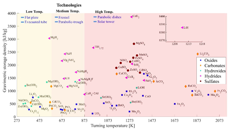
Fig. 6 The gravimetric thermal storage density of selected salts and oxides at the turning temperature. From the [8].
It is evident from Fig. 6 that hydroxides are a promising option for temperatures ranging from 250 to 1250 K. Magnesium and calcium hydroxides exhibit optimal characteristics for temperatures below 700 K, while strontium and barium hydroxides show promise for higher temperatures, albeit with slightly lower thermal storage capacity. Among carbonates, calcium, strontium, and barium demonstrate the best attributes for high temperatures; Magnesium and zinc exhibit similar characteristics to hydroxides at moderate temperatures. The selected sulfates exhibit superior characteristics to hydroxides and carbonate at high temperatures. However, it is essential to conduct a detailed evaluation due to the production of sulfur dioxide and sulfur trioxide and the cost of materials used in the processes. A thorough analysis of carbonates and lithium hydroxides with high storage capacity at high temperatures is necessary. Additionally, ammonium salts exhibit sufficiently interesting characteristics at intermediate temperatures (between 500 K and 700 K) to warrant separate research.
Thermochemical research at LTQSUAM
The development of thermochemical storage systems follows a precise route to a model of thermal storage integrated into a commercial CSP plant. Fig. 7 describes the objectives and methods for developing thermochemical energy storage technology integrated into a commercial CSP plant.
Our research group is currently working on the first two stages and moving on to the third stage on a pilot scale. We are collaborating with the Concentration and Solar Chemistry National Laboratory of the Renewable Energy Institute (IER-UNAM) research group to develop thermochemical experiments on a larger scale using the laboratory's solar furnace (HoSIER). Also, with the Materials Research Institute (IIM-UNAM) in developing new materials based on perovskite-type oxides. The following sections describe the research carried out in terms of materials to store thermal energy and to generate hydrogen.
More than 100 mixtures [61,65,66] have been proposed for both thermochemical storage and the production of hydrogen and other green fuels. However, not all of them meet the expectations for their use or the basic criteria for their selection [67]. Thermochemical energy storage offers several key advantages [68,69]:
1. High energy storage density: The theoretical capacity of storage is high due to the high enthalpies of reactions by mass or volume. This is important for space within facilities and for transporting energy from distant thermal sources.
2. Storage at room temperature: The products can be cooled and stored at room temperature, simplifying storage of large amounts of materials without needing high-temperature storage. Careful design of reactors and heat exchangers is required to maintain system efficiency.
3. Long-term storage: Thermochemical systems can store energy for long periods without degradation.
4. Ease of transport: Since the products are at room temperature, reversible reactions can transport thermal energy over great distances.
5. High temperature: Some reactions can be carried out at high temperatures to generate electricity and provide constant power.
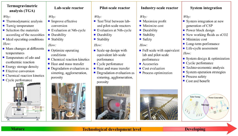
Fig. 7 Objectives and methods aimed at the development of thermochemical energy storage technology integrated into a CSP plant.
The systematization of criteria for the thermochemical energy storage and hydrogen production processes has been proposed by Browns et al. (2002) [70], Abanades (2005) [64], André et al. (2016) [61], and Santamaria (2023) [8]. These criteria can be used to select thermochemical storage systems. The proposed reactions are grouped into hydroxides, carbonates, hydrides, sulfates, pure oxides, mixed oxides, and perovskites. Their evaluation requires thermodynamic analysis before deciding on the best selection. Some of these reactions may be quickly discarded when considering toxicity, environmental security, or economic criteria based on the price of the compounds.
Metal sulfates applied in thermal storage systems
Research at LTQSUAM focused on investigating the potential use of metal sulfates in thermochemical solar heat storage systems. The advantages of various metal sulfates based on Mg, Al, Fe, Co, Ni, Cu and Zn, were analyzed and evaluated according to previous thermodynamic studies [71-73].
The theoretical conditions of decomposition and recombination were studied considering the existence of simultaneous chemical equilibrium states and the possibility of several oxidation states of metals. Simulation tools were used to calculate the minimum value of the Gibbs energy under specific pressure and temperature conditions, and the composition of the equilibrium mixtures was determined [71,74]. The potential of each reaction to store thermal energy was evaluated with theoretical analyses of thermal storage cycles and chemical equilibrium studies. The thermal storage capacity changes depending on the specific reaction, according to the following equilibria:
Table 7 presents the gravimetric storage density for both reactions.
Perovskites
In addition to the study of pure compounds, some mixtures of compounds and mixed oxides have been studied in the literature, including perovskites, for their advantages of structural stability and their ability to reduce sintering phenomena. Perovskites are single-phase non-stoichiometric compounds with high melting points, high mobility of oxygen ions, and exceptional stability at high temperatures. Perovskite oxides are attractive as redox materials due to their relatively low operating temperature and superior oxygen transport capabilities in the crystalline structure at high temperatures. These materials are known for their unique structure, which allows for easy replacement of cations by similar elements. This tolerance to cationic substitution generally improves their transport properties compared to other families, such as spinels, pyrochlores, or garnets [75,76]. The oxygen vacancies in perovskite structures and their oxygen ion-conducting properties make ABO3 perovskites ideal for energy storage through O2 exchange (Eq. 13).
Perovskite oxides have a unique structure known as ABO3, with cation A being alkali, alkaline earth, or lanthanide, and cation B usually being a transition metal. These oxides are promising catalysts for hydrogen production and store thermal energy due to their immunity to structural changes, porosity for oxygen transport, and ease with which they release and occupy sites. Unlike traditional couples in redox cycles, perovskite oxides do not undergo discrete structural phase changes during the redox process, simplifying the reactor where thermochemical reactions occur [77]. Some perovskites offer the interesting ability to store and release oxygen in a continuous way following the variation of temperature. The maximum chemical energy storage was found to be 250 kJ/kg with a reducing condition of 1523 K and pO2,red = 10−3 bar, for the perovskites as La1-xSrxCoyFe1-yO3-δ and La1-xSrxCoyMn1-yO3-δ [78].
To develop a perovskite-type oxide for the conversion of solar energy into fuels (H2 and synthesis gas), two criteria are used: 1) the oxide must present a high release of oxygen at the lowest possible temperature; 2) refers to the thermochemical process favorable for the dissociation of H2O and CO2. In the literature, the catalytic properties of lanthanum-substituted chromites (LaCrO3) have been reported for their application in the direct oxidation of CH4 in anode materials of solid oxide fuel cells (SOFC) [79]. Understanding the peculiarities of doping effects is essential to finding and describing the possible applications of LaCrO3 oxide compounds. The substitution of alkaline earth metals (Ca, Sr, and Mg) and transition metals (Mn, Fe, Co, and Ni) in the LaCrO3 network gives rise to different catalytic behaviors according to the substitution element. For example, in the substitution of sites A and B, Sfeir et al. (2001) [80] report that Sr and Ni are the most active and suitable substituents for the purpose of LaCrO3 anodes in SOFC.
In our laboratory, we have been working with the following materials: the perovskite oxides La0.7Sr0.3Mn0.9Cr0.1O3-δ, La0.2Sr0.8Fe0.8Co0.1Cr0.1O3-δ, and La0.6Sr0.4Cr0.8Co0.2O3-δ. These oxides have been synthesized and characterized. In the synthesis stage, we used the method proposed by Pechini [81], and we applied x-ray diffraction (XRD) and energy dispersive spectroscopy-scanning electron microscopy techniques (EDS-SEM) for the structural and morphological characterization of the oxides. The results of these studies are not reported in this work, as they are still being characterized and subject to preliminary testing.
Sintering and agglomeration phenomena
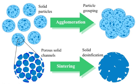
One of the problems that arises during thermochemical storage is the inefficiencies in the cyclic process of endothermic and exothermic reactions since sintering and particle agglomeration phenomena occur. In these phenomena, porosity strongly influences the effective conversion performance.
Figure 8 shows the difference between sintering and agglomeration. The latter involves grouping particles by heating at high temperatures, while sintering refers to the particles' porosity and the solid's densification. Both phenomena prevent gases from diffusing from the surface to the bulk of the material and thus decrease the effective conversion. Several techniques, including ceramic supports and chemical spacers, could solve these problems.
Strontium carbonate improved with different materials
The research group in the LTQSUAM research group joins these efforts to determine the best mixture or composite to achieve high stability and reduce the effects of sintering and agglomeration that occur in cyclic processes of endothermic and exothermic reactions. Below are some of the materials studied by the research group and the most relevant results obtained during the study of these mixtures and composites. Strontium carbonate is gaining relevance because it has a high energy storage density (1366.22 kJ/kg) and very promising conversion rates, but it sinters more easily than other carbonates such as CaCO3.
Interest in strontium carbonate has grown in the last decade due to substantial progress in its performance with different ceramic additives. Some research to improve the performance of strontium carbonate is reported in the literature; P. Ammendola et al. (2020) [82] proposed the mixture of SrCO3 with 19 wt% of Al2O3, authors performed calcination/carbonation cycles at 1323 K, after evaluated 10 cycles they reported an effective conversion Xeff,1=0.43 and Xeff,10=0.33. A.P. Vieira et al. (2021) [83] mixed SrCO3 with 20 wt% of SiO2, the authors evaluated the sample for 15 cycles at an operating temperature of 973 K, they report having obtained a storage density of 658 kJ/kg. N. Amghar, et. al. (2023) [84] used SrCO3 with 10 wt% of ZrO2, they performed calcination/carbonation processes at 1173 K during 10 cycles. Effective conversion reported is Xeff,1=0.86 y Xeff,10=0.69.
Calcium carbonate is a compound that has been extensively studied in the literature; it has a high storage density (1655.75 kJ/kg), and various mixtures have been proposed to avoid sintering effect and achieves high effective conversion values [85].
For instance, J.M. Valverde et. al. (2012) [86] proposes using a mixture of CaCO3 with 15 wt% SiO2, obtaining an operating temperature of 1,123 K, and evaluating it in 100 cycles. They report a storage density of 199 kJ/kg. P.E. Sánchez Jiménez et. al. (2019) [87] propose using a mixture of CaCO3 with 20 wt% MgO, obtaining an operating temperature of 1123 K, evaluating 30 cycles and reporting a storage density of 927 kJ/kg. K.T. Møller et. al. (2020) [88] propose using a mixture of CaCO3 with 20 wt% Al2O3, Ca5Al6O14, obtaining an operating temperature of 1173 K, evaluating 500 cycles and reporting a storage density of 1,060 kJ/kg. R. Anwar et. al. (2023) [89] propose using a mixture of CaCO3 with 20 wt% ZrO2, obtaining an operating temperature of 1157 K, evaluating 40 cycles, and reporting a storage density of 696 kJ/kg.
According to the selection criteria outlined by A. Santamaria and H. Romero-Paredes (2023) for thermochemical energy storage materials [8], key considerations include abundance, high storage capacity, affordability, absence of side reactions, and non-toxicity. Based on a comprehensive review of literature focusing on enhancing the performance of strontium carbonate, this study aims to evaluate the compositions listed in Table 8, showing their respective theoretical CO2 absorption capabilities. These mixtures represent novel materials proposed to improve strontium carbonate's effective conversion in each calcination-carbonation cycle. The proportions specified in Table 8 are based on a mass basis. Table 9 details the purity levels of the materials utilized in these mixtures.
Table 8 Proposed mixtures to improve SrCO3.
| Sample | Composition (wt %) | Theoretical CO2 absorption (wt%) | ||||||
|---|---|---|---|---|---|---|---|---|
| SrCO3 | CuO | CaCO3 | Li2CO3 | ZnO | CeO2 | SnO2 | ||
| SrCO3 | 100 | - | - | - | - | - | - | 29.80 |
| SrCu5 | 95 | 5 | - | - | - | - | - | 28.31 |
| SrCu10 | 90 | 10 | - | - | - | - | - | 26.82 |
| SrCu20 | 80 | 20 | - | - | - | - | - | 23.84 |
| SrCu30 | 70 | 30 | - | - | - | - | - | 20.86 |
| SrCu40 | 60 | 40 | - | - | - | - | - | 17.88 |
| SrCa5 | 95 | - | 5 | - | - | - | - | 30.51 |
| SrCa10 | 90 | - | 10 | - | - | - | - | 31.22 |
| SrCa20 | 80 | - | 20 | - | - | - | - | 32.64 |
| SrLi20 | 80 | - | - | 20 | - | - | - | 35.75 |
| SrZn20 | 80 | - | - | - | 20 | - | - | 23.84 |
| SrCe20 | 80 | - | - | - | - | 20 | - | 23.84 |
| SrSnO20 | 80 | - | - | - | - | - | 20 | 23.84 |
Table 9 Properties of the materials used.
| Compound | SrCO3 | CuO | CaCO3 | Li2CO3 | ZnO | CeO2 | SnO2 |
|---|---|---|---|---|---|---|---|
| Brand | Sigma-Aldrich ≥99.9% trace metals basis | Sigma-Aldrich ≥99.9% trace metals basis | Sigma-Aldrich ≥99.0% | Meyer ≥99.0% | J.T. Baker Analyzed ≥99.0% | Sigma Aldrich 99.9% | Sigma Aldrich 99.9% |
| CAS | 1633-05-2 | 1317-38-0 | 471-34-1 | 554-13-2 | 1314-13-2 | 1306-38-3 | 18282-10-5 |
Methodology
The experiments were carried out using a combined thermogravimetric analyzer (TGA) and differential scanning calorimetry (DSC) STA 449 F3 Jupiter from NETZSCH. This analyzer has a highly sensitive balance (<0.1 μg) and a silicon carbide furnace that allows working at temperatures up to 1773 K. The sample mass used in each experiment was 25.5 ± 5 mg. For the calcination experiments, a controlled argon-inert atmosphere with a 40 ml/min flow rate was maintained. Carbonation procedures were carried out under a CO2/Ar atmosphere with a 30/10 ml/min flow rate. This work proposes the next experimental protocol: first, the calcination stage, wherein the sample is heated at a rate of 30 K/min until reaching 1473 K to ensure complete calcination. Next, carbonation was carried out at different temperatures in each experiment: 1173, 1223, 1273, and 1323 K, and they were maintained for 5 minutes with the gas flow described previously. These stages were iterated twice to observe the multicycle conversion behavior of the sample and determine the optimal carbonation temperature. Once the ideal T carb is determined for the pure compound, it will be the same for all mixtures. Finally, a comparative analysis of the results obtained with the pure compound (SrCO3) and all mixes proposed are carried out to see if improving the conversion rate when passing through the calcination-carbonation cycles is possible. In this case, its performance will be evaluated in 4 cycles.
The microstructure of the samples at different stages was investigated using scanning electron microscopy (SEM) using a JEOL JSM 7600F microscope.
X-ray diffractograms of the samples were acquired before and after the multicycle test using a Bruker D8 Advance diffractometer with Cu K∝ radiation. The data were measured in the range from 15° to 80° in 2θ with a step size of 0.2, for 38.4 s per point.
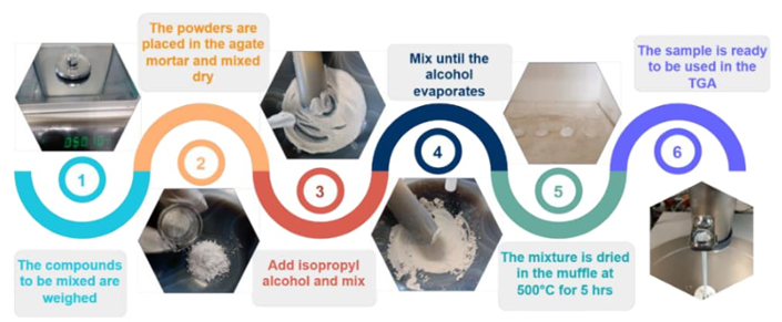
Preparation of SrCO3 based mixes
The mixtures were made as described in Fig. 9. They are prepared so that a composite is not formed, for each addition is expected to stabilize the effective conversion in each cycle and delay the sintering of SrCO3.
Effective conversion and energy density
The results obtained at each mix will be compared to determine the operating conditions where a higher conversion rate is obtained. The effective conversion (X eff ) is defined as follows [90]:
where m i and m carb,i are the mass of the sample before and after the storage and release steps in the N cycle, and MMSrO and MMCO 2 are the molar masses of SrO and CO2, respectively.
The calculation of energy density is determined with the following equation:
where ΔH R is 5318.18 kJ/kg CO2 and m CO2 is m carb,i - m i .
To calculate the volumetric energy density, GJ/m3, Eq. (17) is multiplied by the density of the oxide being carbonated, in this case strontium oxide:
Results
Firstly, the operating parameters of pure strontium carbonate were determined with the help of TG analysis. The calcination temperature (T cal ) was established at 1473 K, slightly higher than T* (1423.15 K), so that dissociation is promoted. The carbonation temperature (T carb ) is in the range of 1173 K to 1373 K, below T* to promote recombination. However, the experiments showed that the best carbonation behavior is obtained at T carb = 1173 K.
With these parameters pure strontium carbonate was evaluated during nine calcination/carbonation cycles. Fig. 10 shows the results of effective conversion, volumetric energy density obtained and XRD patterns.
Fig. 10(A) shows the results as a function of the effective conversion and the energy density storage, it is observed that in the first cycle, 99.76 % effective conversion is achieved. As the cycles pass, the conversion decreases, having in the last cycle an effective conversion of 2.33 %, which coincides with the behavior reported by S. Zare Ghorbaei and H. Ale Ebrahim, who evaluated 20 cycles; In the last cycle, they reported a conversion yield of approximately 1% [91]. The theoretical volumetric energy density (Dv) of SrCO3 is 10.61 GJ/m3 [92]. It is observed that in the first cycle, it is very close to this, but then it decreases similarly to the effective conversion, reaching 1.24 GJ/m3 in the 9th cycle. Fig. 10(B) shows the XRD patterns of unprocessed SrCO3 in the TGA, and after 9 cycles of calcination-carbonation, ending in carbonation. It is observed that it coincides with ICDD-PDF 00-005-0418 of SrCO3, and as the cycles pass, it also coincides with ICDD-PDF 00-027-1438 of Sr(OH)2 8H2O and with ICDD-PDF 00-019-1276 of Sr(OH)2. The growth of characteristic peaks indicates that the material is agglomerating. Fig. 11 shows the scanning electron microscopy (SEM). Fig. 11(A) shows the sample white of SrCO3 has a cylindrical shape, and in Fig. 11(B), the sample after 4 cycles, and it is clearly seen as the particles are agglomerating and most likely also sintering, which is why the effective conversion is rapidly reducing.
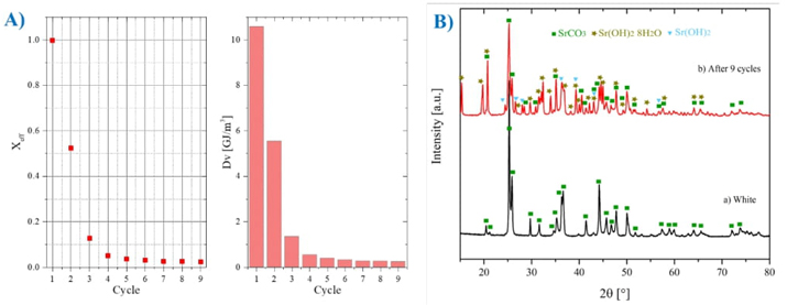
Fig. 10 SrCO3 analysis results (A) effective conversion and volumetric energy density results, (B) XRD for SrCO3 before and after being subjected to nine calcination/carbonation cycles ending in carbonation.
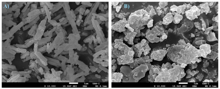
Fig. 11 SEM micrographs of SrCO3, (A) without process and (B) of the samples subjected to 4 calcination/carbonation cycles, ending in carbonation.
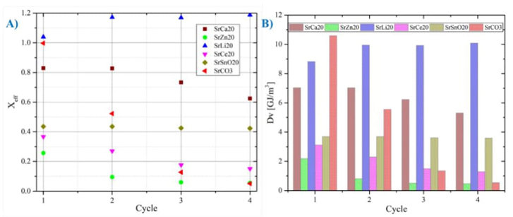
The proposed mixtures were evaluated with the same operating temperatures (T cal =1473 K and T carb =1173 K) defined for strontium carbonate. Fig. 12 shows the results obtained where the following observations stand out:
a) The mixture SrLi2O (80 % SrCO3+ 20 % Li2CO3) shows the best behavior with the passage of cycles, however, it generates inconveniences in the handling of this compound since a solid-liquid phase change is observed. Therefore, it is advisable to study the mechanisms of use of this compound.
b) The mixture SrCa2O (80 % SrCO3+ 20 % CaCO3) also shows acceptable behavior during each cycle, since a high conversion rate is maintained during each cycle. Fig. 13(A) shows that after four cycles, it has X eff,4 =0.62, which is compared to SrCO3 X eff,4 =0.05; This represents 12 times better with the proposed mixture.
c) Another interesting mixture is SrSnO2O (80 % SrCO3+20 % SnO2), this has a lower effective conversion rate but is more stable; For the first cycle we have X eff,1 =0.43, and for the fourth cycle, X eff,4 =0.42, which compared to the pure compound still has an 8 times better improvement with the proposed mixture.
Although it does not have a very high effective conversion like the SrCa20 mixture, it is more stable, and a more in-depth study can be carried out to evaluate the feasibility of using this compound as an energy storage medium.
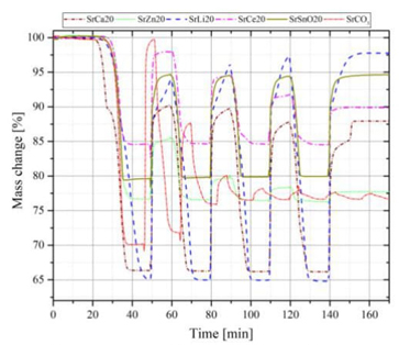
Fig. 12 Analysis of the different mixtures with 20% additive with respect to the pure SrCO3 compound. Sample nomenclature: SrCa2O (80 % SrCO3+ 20 % CaCO3), SrLi2O (80 % SrCO3+ 20 % Li2CO3), SrZn2O (80 % SrCO3+ 20 % ZnO), SrCe2O (80 % SrCO3+ 20 % CeO2) and SrSnO2O (80 % SrCO3+20 % SnO2).
Furthermore, the volumetric energy density (Dv) of each of these mixtures was calculated and compared with the Dv value of SrCO3.
Fig. 13(B) shows that the mixture with the best performance during the four cycles is that of SrLi20 with an average of Dv =9.7 GJ/m3, followed by SrCa20 with an average of Dv=6.46 GJ/m3, and in third place, SrSnO20. mixture with an average of Dv =3.65 GJ/m3.
All values Dv are higher than that of pure strontium carbonate, which has an initial average of Dv =4.51 GJ/m3 but it decreases quickly.
For all the above, the properties observed in the mixtures of SrCa20 and SrSnO20 make them feasible to implement in a thermochemical energy storage system that operates under central tower plant conditions. These proposals seek to increase the capacity factor of a central solar tower power plant to contribute to mitigating climate change with new forms of energy generation from concentrated solar energy.
Conclusions
The development of thermal energy storage systems covers a broad spectrum. Sensible heat systems are currently the most used in solar power plants, so they have experienced considerable technological advances. Thermochemical systems have a high application potential. Research shows they have gained increasing relevance and interest within the global scientific and technological community in recent years.
Research at the Solar Thermochemistry Laboratory at UAM has significantly advanced systems based on reversible reactions. Initial attention was focused on sulfates because they have a high gravimetric heat storage density. However, there are substantial drawbacks during sulfate dissociation.
In recent years, research has been oriented toward studying other less complex compounds for their integration into solar-thermal energy storage systems. For this purpose, strontium carbonate was selected. The research has focused mainly on turning temperature, storage capacity, and effective conversion.
In this sense, chemical dopants and physical spacers have been proposed to address these issues. This approach has shown promising results, leading to an increased conversion rate and improved performance during long cyclic processes.
The findings indicate a substantial improvement in the effective conversion of the strontium-calcium carbonates and strontium-tin oxide mixtures with 12 and 8 times than the pure compound, respectively.
Furthermore, this study found that the mixture of strontium and lithium carbonates can work adequately but melts at 973 K, which is lower than the carbonation temperature. This phenomenon limits its development and causes more sintering as the cycles progress.
On the other hand, the mixture of strontium carbonate with tin oxide is the most stable, even though the calcination doesn't completely occur. However, this mixture is also a promising option for thermochemical storage systems.
We have been working on preparing compounds that guarantee excellent stability and durability properties. By synthesizing strontium-based cermet, we aim to achieve greater stability and reduce particle agglomeration caused by fluctuating polarizations due to temperature changes and secondary chemical reactions that occur during reversible reactions.
Additionally, the research focuses on synthesizing, characterizing, and applying perovskites for energy storage through RedOx reactions and hydrogen production through these compounds' reduction-hydrolysis. This research will help us achieve our goal of improving solar energy use and reducing the impact of source intermittency.

