


 nueva página del texto (beta)
 Inglés (pdf)
 Artículo en XML
 Referencias del artículo
 Enviar artículo por email
 Citado por SciELO
  Similares en
SciELO
Similares en
SciELO 
 Permalink
1. Introduction
In recent years, the increasing global fossil fuel crisis has accounted for serious global warming events like extreme climate changes, severe environmental damage, etc., due to its effects of producing various greenhouse gas emissions. Lithium-ion batteries (LIBs) generally play crucial roles in the concept of carbon neutrality and sustainable futures, as they are currently becoming primary energy storage for various daily portable electronic devices and for the utilization of clean and renewable energy like solar panels and wind turbines that often hit by fluctuations due to insufficient sources (Behabtu et al., 2020). LIBs, in general, offer significantly higher specific capacity and better electrochemical stability over other energy storage technology and have become a noble breakthrough since their first commercialization back in 1991 by Sony (Chayambuka et al., 2020; Durmus et al., 2020; Li et al., 2018). However, LIBs also have limitations in further high-energy and high-power applications, including long-range electric vehicles and large-scale power grids (Ahmad et al., 2021; Kebede et al., 2022). Hence, a high-voltage cathode is becoming a promising material candidate for next-generation LIBs to meet these demands. The cathode material is generally acknowledged as the main component in the state-of-the-art LIBs that determines their overall performances, such as cycle stability, rate capability, as well as energy, and power density. Cathode materials with the ability to operate at high voltage can be divided into three groups, including 4.5 V class (LCO, NCA, NMC, LMO), 4-5 V class (LiMPO4, M= Ni, Co, Mn), and 5 V class (LiNi0.5Mn1.5O4 or LNMO) (Zhu et al., 2020).
The LNMO is often substantially devoted and extensively investigated as an ultra-high voltage cathode. LNMO, originally from cation-substituted spinel lithium manganese oxide, has lately received much research attention (Liang et al., 2020; Qureshi et al., 2022; Xu et al., 2017). LNMO is one of the cobalt-free cathode materials, allegedly involving child labor and severe environmental damage, which is geographically concentrated in politically unstable regions in Central Africa (Schmuch et al., 2018). Even though the widespread use of cobalt can preserve higher energy density, it has low abundance, intrinsic toxicity, and high fluctuation price, reducing the competitiveness of cobalt-containing materials, as cathodes accounted for about 40% of the LIB costs. As a result, the absence of expensive cobalt plus no excessive lithium makes LNMO potentially have added value in the cathode development. Although its theoretical capacity is not as large as that of other high-voltage cathodes, which only 147 mAh g-1 compared to 274 mAh g-1 (LCO), 200 mAh g-1 (NCA), and 190 mAh g-1 (NMC), LNMO can provide the highest potential windows in the range of 4.7 to 5.0 V (vs Li/Li+) increasing the energy density up to 30% higher (Qureshi et al., 2022). However, its rapid capacity decay resulting in short cycle life limits its application and commercialization when achieving high voltage operations above 4.7 V, especially on full-cell with graphite anode and elevated temperatures higher than 50 °C (Liang et al., 2020).
The remarkable properties of LNMO cathodes were majorly attributed to their structure, which is favorable for accommodating interfacial stability during cycling (Palaniyandy et al., 2022). The disordered structure of the cation would lead to oxygen deficiencies and rock-salt impurities, finally generating transition metal (Aktekin et al., 2019). Extensive research has shown that transition metal dissolution in LNMO is tightly coupled to gas formation from electrolyte decomposition during the first charge within the first hour (Hestenes et al., 2023). In addition, deep discharge lower than 3.0 V of LNMO would undergo a complex phase transformation from cubic to tetragonal, further reducing Mn4+ to Mn3+ and leading to severe structural distortion (Kong et al., 2023). This disadvantage, in summary, comes from transition metal dissolution, electrolyte decomposition, and cathode-electrolyte interphase (CEI) formation. There are numerous possible ways to solve it, the most likely including particle engineering, surface coating, and electrolyte modification (Xu et al., 2017).
Electrolyte is the battery component responsible for facilitating the movement of Li ions between cathodes and anodes, allowing the flow of charge during battery cycling operations. Lithium hexafluorophosphate (LiPF6) salt dissolved in carbonate-based solvents, which has high conductivity, still prevails as the primary electrolyte in commercial LIBs (Campion et al., 2005). Unfortunately, integrating high-voltage cathode with the most widely used electrolytes poses significant drawbacks. When operating at a high working potential (> 4.2 V), there are still bottlenecks imposed by the hydrolysis reaction of LiPF6, leading to the formation of highly corrosive byproduct HF and undergoing decomposition reactions to form PF5 gas (Guéguen et al., 2016). These reactions would accelerate transition metal dissolution, react with the CEI, and corrode other battery components, leading to inadequate performance degradation (Liu et al., 2021). For long-term application, the battery will seriously perform capacity fading and reduce Coulombic efficiency. Gas evolution cause pressure build-up, leading to cell swelling, electrolyte leakage, and, in extreme cases, thermal runaway and battery failure, which impact the main safety risks for users and the environment (Mattinen et al., 2020). Those severe issues can be addressed by electrolyte optimization through solvents and additives with high anti-oxidative ability and surface-forming capability, as well as breakthrough research to widen its working potential (Hou et al., 2023). Between those two, electrolyte additives can act not only to prevent electrolyte decomposition but also to construct stable CEI formation. Furthermore, it is also essential to understand the failure mechanisms and develop the targeted approaches. To cater to the hash requirements of high-voltage cathodes, electrolyte modification is a modest solution than the others, even though recent progress needs to find the best optimization or combination with multiple compound options available.
Boron-containing compounds, like lithium bis(oxalate)borate (LiBOB), have been widely studied as a promising lithium salt due to the high thermal stability of BOB- anion in a wide potential window as well as surface-forming capability to enhance the electrochemical stability of high-voltage cathodes (Chen et al., 2006; Sheina et al., 2019; Xu et al., 2005). LiBOB and other lithium borate additives on LiPF6 electrolytes result in borate oxidation on the LNMO surface, deposing a passivation layer and inhibiting transition metal dissolution (Dong et al., 2017). Other results of LNMO modified with phosphoric acid enhance the overall performances of the cells, including specific capacity and Coulombic efficiency, especially in high-voltage operation with graphite anode (Abeywardana et al., 2019). It also has a clear improvement by a factor of 3 compared to without additives, including high cycling stability and current rates of up to 800 cycles and 1 C, respectively, when operating between 3.5 and 5.0 V with elevated temperatures at 50 °C than other already known additives for high-voltage cathodes such as 1-vinyl-1,2,4-triazole (VTA), 1-vinyl imidazole (VIM), and dimethyl-2,5-dioxahexanedioate (DDD) (Hofmann et al., 2019). In addition, several outstanding achievements have also explored LiBOB additive in other high-voltage cathodes, including LiMn2O4 (Wang et al., 2018), Ni-rich (Cheng et al., 2021; Täubert et al., 2010), and Li-rich (Lee et al., 2014; Nayak et al., 2015), which also showed better rate performances. Still, many researchers only focused on LiBOB additive in the full-cell configuration, in which the half-cell with Li-metal showed another problem where dendrite growth is notoriously inevitable in addition to several other challenges, including large electrolyte consumption and severe volume changes (Liu et al., 2020; Luo et al., 2021; Zhang et al., 2020). Modifying electrolyte chemistry based on interface mechanism is also one of the strategies to overcome the potential safety risks Li-metal poses for practical applications. Besides, Li-metal offers many advantages in the prospects of anode-free LIBs, denoted as Li-metal batteries, affording the highest theoretical capacity (3,860 mAh g-1), lowest redox potential (-3.04 vs. SHE), and lowest gravimetric density (0.534 g cm-1) over any currently available anode.
LiBOB additive has already shown excellent prospects and significant interest in addressing the current issues in liquid electrolytes and layered cathodes to mitigate electrolyte decomposition and transition metal dissolution (Abeywardana et al., 2019; Chen et al., 2006; Dong et al., 2017; Hofmann et al., 2019; Xu et al., 2005). However, the results so far do not clearly show the optimal amount of LiBOB ratio in LiPF6/LiBOB mixed salt electrolyte, in which the larger ratio has been less explored. In this study, we investigated the effects of 10% and 20% of the LiBOB content for optimizing the electrochemical performance of high-voltage LNMO cathodes, including specific capacity and rate capability. We assumed that the synergistic effects between LiBOB and LiPF6 have a certain optimal amount for increasing electrolyte conductivity, improving voltage stability, providing stable reversibility, and protecting the cathode surface in high-voltage windows for the next-generation 5 V class of LIBs in future application demands.
2. Materials and methods
2.1. Electrolyte preparation
The baseline electrolyte was made of 1.0 M LiPF6 (Sigma Aldrich) and 0.5 M LiBOB (Sigma Aldrich) salts, each dissolved in a solvent mixture of ethylene carbonate (EC), diethyl carbonate (DEC), and dimethyl carbonate (DMC) at a ratio of 1:1:1 (v/v). The electrolyte mixtures were prepared by combining 1.0 M LiPF6 salt with 10% and 20% LiBOB salt (w/w) in a hot plate magnetic stirrer at 50 °C and then dissolved in the same solvent mixtures. Since the electrolyte preparation had a particularly high oxygen and water content requirement, all processes, including storing electrolyte samples, were carried out in a glove box filled with inert Argon gas (O2 < 1 ppm, H2O < 1 ppm).
2.2. Cathode preparation
The cathode material was made of LNMO (MTI Corp.), Super-P acetylene black (CB), and polyvinylidene fluoride (PVDF) at a ratio of 8:1:1 (w/w) with N, N-dimethylacetamide (DMAc, Merck) as the solvent. The slurry mixture was prepared using a vortex mixer (D-Lab) at room temperature. First, PVDF as a binder was dissolved in DMAc for 15 min, and then CB as a conductive additive was added for another 15 min. Finally, LNMO as an active material was dropped on the mixture and continued by mixing for around 30 min to form a homogeneous slurry. The slurry was cast onto the aluminum foil in an automatic film coater (MTI Corp.) using the Doctor Blade method, with a thickness of 200 microns, and dried in a vacuum oven at 80 °C for 1 h. The cathode sheet was then processed into calendaring and punched into a circular shape with a diameter of 15 mm in a mass loading of 6.06 mg cm-2.
2.3. Cell configurations
Three CR2032-type coin cell configurations were assembled in a dry Ar-filled glove box for each electrolyte sample. The electrolyte-wetted polypropylene (PP, Celgard) sheet as a separator was sandwiched between (1) two stainless steel (SS) electrodes, (2) Li-metal and SS electrodes, and (3) Li-metal and LNMO cathode. The first configuration was used to measure ionic conductivity; the second configuration was used for linear sweep voltammetry (LSV) to evaluate the stability window of the electrolytes; while the third was used to measure the electrochemical performances with half-cell configuration, which includes electrochemical impedance spectroscopy (EIS), cyclic voltammetry (CV), and charge-discharge (CD). Coin cells were washed with ethanol and left for 1 h at room temperature prior to the electrochemical measurements.
2.4. Electrochemical measurements
EIS was conducted in a frequency range from 0.1 Hz to 100 kHz with an AC amplitude of 10 mV using Autolab PGSTAT302N (Metrohm). LSV was recorded until the voltage reached 5.0 V, while CV was cycled in a voltage range from 3.5 to 5.0 V, both at a scan rate of 0.1 mV s-1 using Automatic Battery Cycler WBCS3000 (WonATech). CD was first performed at 0.1 C for 5 cycles over a voltage window from 3.5 to 5.5 V (vs. Li/Li+) using Battery Analyzer BST8-WA (MTI Corp.). CD was also tested at various C-rates of 0.1, 0.2, 0.5, and 1 C for 5 cycles, respectively, to test the rate capability of the battery.
3. Results and discussion
The ionic conductivity is one notable parameter for both electrolytes and separators. High ionic conductivity can remarkably improve the specific capacity and electrochemical performance of LIBs. Figure 1 shows the EIS measurement by sandwiching the electrolyte-wetted PP separator between two SS electrodes to attain the bulk resistance, which is the intercept on the Z axis of the Nyquist plot, and further calculate the ionic conductivity of the electrolyte-wetted PP separator. The ionic conductivity σ was calculated by the following equation:
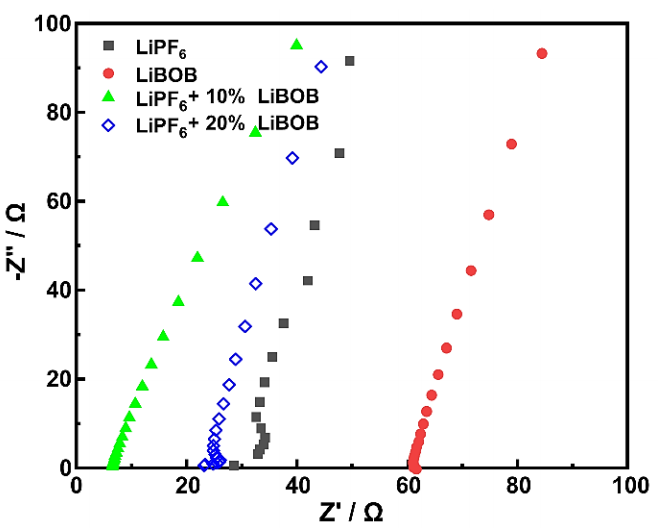
Figure 1 The Nyquist plot of the cells assembled SS//electrolytes//SS conducted in a frequency range of 0.1 Hz to 100 kHz with an AC amplitude of 10 mV.
where 𝑙 represents the thickness of the PP separator of 16 μm, 𝑅 𝑏 is the bulk resistance of the electrolyte-wetted PP separator, and S indicates the effective area of the PP separator and SS electrodes with a diameter of 1.55 cm.
Table 1 represents the measured bulk resistance (R
b
) and ionic conductivity (
Table 1 The bulk resistance and ionic conductivity of different electrolytes.
| Sample | Rb (Ω) |
|
|---|---|---|
| LiPF6 | 28.479 | 0.030 |
| LiBOB | 61.705 | 0.014 |
| LiPF6 + 10% LiBOB | 6.602 | 0.129 |
| LiPF6 + 20% LiBOB | 23.128 | 0.037 |
The stability window is also a crucial parameter for LIBS, especially for the next generation of high-voltage cathode, as it refers to the comprehensive voltage limitation indicated by the oxidation potential of the electrolyte and separator. Figure 2 shows the LSV measurement by sandwiching the electrolyte-wetted PP separator between Li-metal and SS electrodes to evaluate the significant increase in current at a given potential. LiBOB and other boron-containing electrolytes have been widely known to have a wide potential window, which in this research can be shown to have a stability window of up to 4.1 V (vs. Li/Li+). On the other hand, the current begins to rise rapidly at around 3.4 V (vs. Li/Li+) for the baseline LiPF6 electrolyte, demonstrating the oxidation peak.
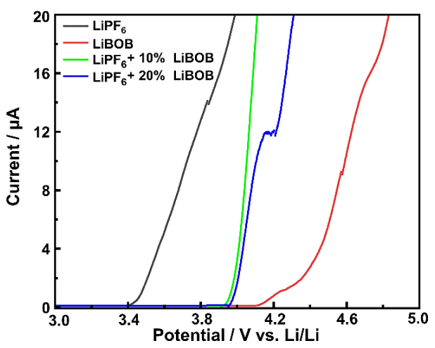
Figure 2 The LSV curves of the cells assembled Li//electrolytes/SS recorded in a voltage range between 3.0 to 5.5 V at a scan of 0.1 mVs-1
The LSV curves show the LiBOB addition with only small amounts can significantly increase the stability window and decrease the oxidative decomposition of the LiPF6 electrolyte, as both 10% and 20% of LiBOB addition exhibit a current rise above 3.9 V (vs. Li/Li+) followed by continuous growth with the voltage increase. This finding shows the positive effect of adding LiBOB to LIPF6-based electrolytes in LIBs, showing a significant increase in the stability window of the battery and allowing them to operate at higher voltage without undergoing oxidative decomposition or other undesirable reactions. It is essential and potentially leads to improved battery performance, longer cycle life, and enhanced safety in LIB applications requiring higher voltage operations.
The electrochemical performance was analyzed by assembling the half-cell configuration with Li-metal as the reference and counter electrodes and the LNMO cathode as a working electrode for the baseline electrolytes and LiPF6/LiBOB mixed salt. A series of electrochemical measurements were carried out to evaluate different parameters of the LIBs. The initial performances were evaluated from CV and CD curves, while the rate capability was tested with various C-rates of all electrolyte chemistries. After that, the overall performances were analyzed by comparing dQ/dV curves and the Nyquist plot of different electrolytes. All measurements were used to study the effect of LiBOB addition on LiPF6 electrolytes from their baseline electrolyte on the half-cell LNMO cathode.
The CV measurements were used to evaluate the electrochemical polarization of the LNMO cathode, which shows the redox peak of transition metal in LNMO, as well as the reversibility and effectivity of the redox reaction. Figure 3 shows the CV curves of the half-cell in LiPF6, LiBOB, and LiPF6/LiBOB mixed salt. All samples generally possess similar voltammogram profiles and curve characteristics for a typical LNMO cathode. Two major redox peaks appear at a potential around 4.1 and 5.0 V (vs. Li/Li+), indicating the spinel structure characteristics of the LNMO cathode. The first redox peaks are attributed to the redox reaction of Mn3+/Mn4+ couples, while the second peaks are ascribed to the contribution of Ni3+/Ni4+ couples (Kong et al., 2023; Liang et al., 2020; Palaniyandy et al., 2022). The ratio between two redox peaks for LiPF6/LiBOB mixed salt is similar to the LiPF6 baseline electrolyte, indicating the main contribution of Li-ion insertion/extraction to the spinel structure of the LNMO cathode is from Nickel. However, the lower the LiBOB ratio in mixed salt, the lower the Mn redox peaks, indicating the possibility of lower transition metal dissolution. These results show that adding LiBOB at a certain proportion can effectively improve the overall performance of LIBs with LiPF6-based electrolytes. Moreover, the LiPF6/LiBOB mixed salt also shows lower polarization, indicating that the LiBOB addition in the LiPF6 electrolyte can accelerate the faster Li-ion insertion/extraction processes, confirming the effect of higher ionic conductivity in the LiPF6/LiBOB mixed salt. On the other hand, LiBOB baseline electrolytes have smaller redox peaks and peak ratios, showing poor electrochemical performances with low reversibility compared to LiPF6 baseline electrolytes. Moreover, its redox reaction in the high-voltage operation is the least optimal, indicated by the lowest Ni redox peaks.
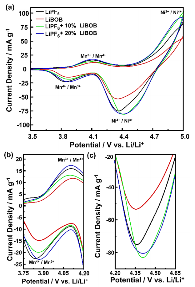
Figure 3 (a) The CV curves of the half-cell at a scan rate of 0.1 mV s-1 and enlargement for the (b) Mn redox peaks and (c) Ni reduction peak.
The charge-discharge (CD) measurements were used to analyze the electrochemical behavior of the LNMO cathode, which shows the capacity profile and plateau area. Figure 4 shows the 4th cycle of the CD curves of the half-cell in LiPF6, LiBOB, and LiPF6/LiBOB mixed salt measured at a current rate of 0.1C. The plateau area seems stable at a potential around ~4.7 V (vs. Li/Li+), indicating that different electrolyte chemistries do not affect the overall electrochemical behavior of the LNMO cathode. Table 2 lists the charge capacity ( 𝐶 𝑐ℎ ), discharge capacity ( 𝐶 𝑑𝑐ℎ ), and Coulombic efficiency (CE). The measured charge/discharge capacities for the half-cell containing LiBOB electrolyte were poorer, with a slightly lower plateau area than the LiPF6 electrolyte. However, despite the lower capacity, the CE was significantly better for the LiBOB electrolyte of up to 96.12%, whereas the LiPF6 electrolyte achieved only 86.60% of CE. These results indicate that the formation of the CEI layer due to BOB- anion starting to appear even from the earlier cycle, agreeing with previous research (Cheng et al., 2021; Täubert et al., 2010).
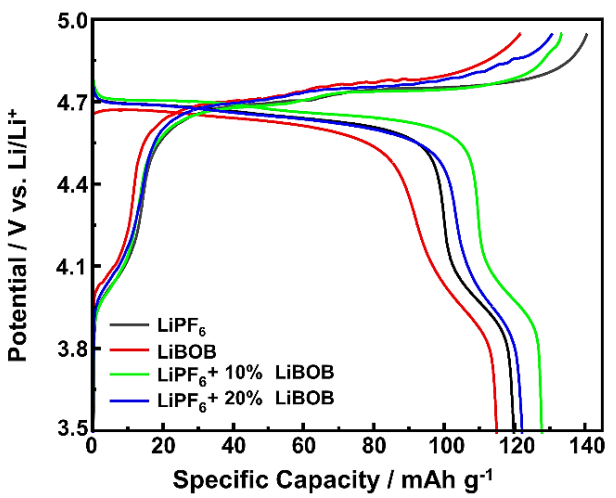
Table 2 The measured capacity values of the half-cell at 0.1C.
| Sample | Cch (mAh g-1) | Cdch (mAh g-1) | CE (%) |
|---|---|---|---|
| LiPF6 | 140.7 | 121.8 | 86.60 |
| LiBOB | 121.8 | 117.0 | 96.12 |
| LiPF6 + 10% LiBOB | 133.5 | 129.1 | 96.76 |
| LiPF6 + 20% LiBOB | 130.8 | 124.2 | 94.91 |
Despite the useful contribution of protecting CEI layers, however, this can also decrease the overall performance of the LNMO cathode. Adding LiBOB in the LiPF6 electrolyte has a significant effect, leading to a substantial increase in CE. Specifically, with the incorporation of 10% LiBOB, reaching 96.76%, and with 20% LiBOB addition, it remains as high as 94.91% of CE. The higher CE indicates that only a small fraction of electrochemical side reactions occurs compared to the baseline LiPF6 electrolyte (Lee et al., 2014). The mixed salts of LiPF6 with 10% LiBOB have the highest charge/discharge capacities of up to 133.5 and 129.1 mAh g-1, respectively, better than the results from the previously reported (Abeywardana et al., 2019; Hofmann et al., 2019), and demonstrate better reversibility indicated by slightly higher discharge potential in the plateau area than other electrolyte chemistries. These results show the crucial role of LiBOB addition to maximizing the Li-ion insertion/extraction processes to the spinel structure of the LNMO cathode and also suggest that the effect of LiBOB addition has the optimum amount to achieve the highest specific capacity of the LNMO cathode, in which a higher proportion of 20% of LiBOB addition begins to reduce the electrochemical performance and tends to behave like LiBOB baseline electrolyte. The greater the LiBOB addition, the greater the CEI formation from its initial charge/discharge, reducing the capacity profile and plateau area. In addition, even though the displayed oxidation potentials (Figure 2) are below 5 V, the actual performances of the electrolyte on LIB devices can achieve a stability window at a higher potential, reaching 5.5 V (Dong et al., 2017). These results demonstrate that the LiPF6 electrolyte with LiBOB addition can fully meet the requirements and demands of high energy and power of high-voltage cathodes.
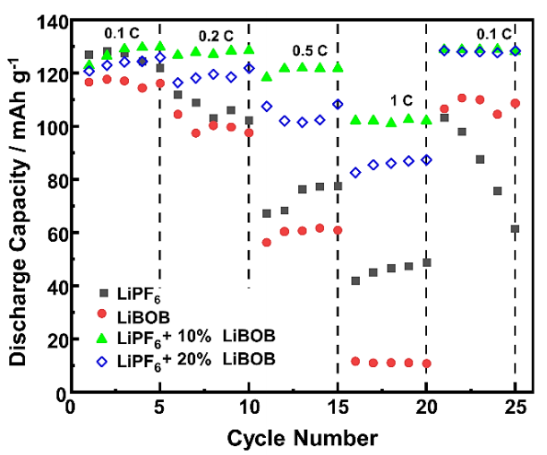
Rate capability is the ability of LIB cells to keep their discharge capacity as high as possible, along with its stability over different current densities. LIB cells with high rate capability can generate considerable energy and power and suffer from electrochemical polarization even at a high current load or C-rate. Figure 5 shows the rate capability of the half-cell with various C-rates from 0.1C to 1C. At the initial formation cycle, the discharge capacity delivered by all electrolyte chemistries is almost the same at a low C-rate, ranging between 117 to 129 mAh g-1 and consistent with the results from the CD curves. However, significant differences are observed at a high C-rate of 0.5C, and the differences increase as the C-rate increases further to 1C. Both LiPF6/LiBOB mixed salt keep their discharge capacity above 100 mAh g-1, while the baseline electrolytes slowly decrease continuously to below 80 and 60 mAh g-1 for the LiPF6 and LiBOB electrolytes, respectively. Other researchers have also observed a similar trend with different high-voltage cathodes (Cheng et al., 2021; Täubert et al., 2010; Wang et al., 2018). At high C-rates, LiPF6 electrolytes with 10% LiBOB show higher discharge capacity and better cycle stability than those with 20% LiBOB addition, indicating their synergistic effect for combining the advanced properties of both types of salt. When the C-rate is changed back to the initial 0.1C, the LiPF6 electrolyte suffers a consistently severe decline in discharge capacity, indicating poor rate capability after being charged/discharged with high current loads and further undergoing cell failure. For LiBOB-containing electrolytes, these results suggest that the appearance of protecting CEI layers can positively maintain the overall electrochemical performances with excellent rate capability (Chen et al., 2006; Xu et al., 2005). LiPF6 electrolyte with 20% LiBOB, even though it showed a higher discharge capacity decline than 10% LiBOB addition, can still restore its maximum electrochemical performances with high discharge capacity when returning to a C-rate of 0.1C, indicating the positive effect of LiBOB addition to solve the problem on LNMO cathode with traditional LiPF6-based electrolyte.
Differential capacity is a widely used method to study LIB aging by identifying and quantifying the various degradation processes related to the active material phase transformation (Jehnichen et al., 2019). Aging mechanisms can be due to the loss of conductivity, available Li-ion, and active material (Kim et al., 2013). Figure 6 shows the dQ/dV curves of the half-cell for the 1st and 25th cycles. There are also two region redox peaks at a potential range of 3.9 to 4.1 V and 4.5 to 4.9 V (vs. Li/Li+), similar to the results from the CV curves. However, it can be clearly shown that the major redox peaks split into two distinguished peaks, corresponding to the redox reaction of Ni2+/Ni3+ and Ni3+/Ni4+ couples. The dQ/dV curves also show the Nickel contribution of Li-ion insertion/extraction since a partial reduction of the Mangan has a minor contribution to the ideal spinel structure of the LNMO. In the 1st cycle, as given in Figure 6a, both oxidation peaks, in which Ni2+ changes to Ni3+ and subsequently to Ni4+ and back over the entire cycle, occur at relatively same potential of 4.68 - 4.69 V and 4.74 - 4.75 V (vs. Li/Li+) for the first and second oxidation reaction, respectively. The LiPF6 baseline electrolyte possesses the highest differential capacity peaks, indicating the highest specific capacity, as previously shown in the rate capability test at the initial 0.1C.
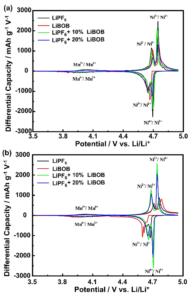
Figure 6 The dQ/dV curves of the half-cell at 0.1C for the (a) 1st cycle and (b) 25th cycle of the rate capability test.
The two baseline electrolytes exhibit a voltage shifting of oxidation peaks to a higher voltage and reduction peaks to a lower voltage, with a peak height decreasing towards different degradation mechanisms after the 25th cycle, as given in Figure 6b. The mechanisms that occur in the LiPF6 electrolyte are due to the electrolyte decomposition and cathode degradation after a high C-rate of 1C, while in the LiBOB electrolyte are assumed to be due to the severe CEI formation, reducing the availability of Li-ion for migration between Li-metal and LNMO cathode (Nayak et al., 2015). Although the capacity loss of the LiPF6 electrolyte is more drastic, a voltage shifting of the LiBOB electrolyte is more severe at around 0.03 - 0.05 V compared to 0.01 - 0.03 V (vs. Li/Li+) for the LiPF6 electrolyte. These results suggest that the degradation through CEI formation that is increasingly thicker in each cycle is eventually not better than a typical degradation mechanism in the LiPF6 electrolyte due to irreversible Li-ion consumption. Also, these protecting CEI layers have several limitations, especially at a high C-rate above 0.5 C, indicating their useful contribution is needed but only in small proportions to maintain the dual effect of excellent rate capability and high specific capacity and to prevent LIB cell failures.
Both LiPF6/LiBOB mixed salts show almost no existence of a voltage shifting even with a higher peak compared to the 1st cycle. However, the LiPF6 with 20% LiBOB still shows a lower differential capacity peak than using only 10% LiBOB addition, confirming that the small amount of LiBOB is sufficient to effectively prevent the loss of active material by forming an optimum protecting CEI layers. Notably, the differential capacity can be an early indication to study the effect of CEI formation from BOB- anion on the surface of the LNMO cathode based on their electrochemical performances (Jehnichen et al., 2019). In other words, the presence of BOB- anion from LiBOB contributes to the formation of CEI layers, which can protect the electrode surface from damage caused by undesirable reactions, such as the formation of HF and PF5 gas produced from the reaction between LiPF6 and existing water content (Chen et al., 2006; Xu et al., 2005).
The EIS measurements were employed to investigate the ohmic effects of the electrolyte on the electrochemical reactions at the surface of the LNMO cathode. Figure 7 (a) shows the Nyquist plot of the half-cell before and (b) after 25 cycles of the rate capability test. All electrolyte chemistries show a typical Nyquist plot consisting of a semi-circle in the high-frequency region and a linear tail or Warburg impedance in the low-frequency region. Figure 7 also shows the fitted curve of the Nyquist plot with the equivalent circuit, in which the 𝑅 𝑠 represents the resistance from the electrolyte, R ct represents the resistance from the interface of LNMO or Li-metal with the electrolyte, and 𝑊 corresponds to the Li-ion diffusion at low frequencies. Table 3 summarizes the measured solution and charge transfer resistance obtained using this equivalent circuit. Before the cycle, all LiPF6/LiBOB mixed salt had a relatively lower charge transfer resistance than both baseline electrolytes, confirming the better ionic conductivity of this mixed salt. In addition, the initial Warburg profile of the LiPF6 with 10% LiBOB is similar to the LiPF6 electrolyte, while the 20% LiBOB addition is more identical to the LiBOB electrolyte. These results suggest that the small amount of LiBOB does not affect the overall behavior of the LiPF6 electrolyte, and their compatibility still preserves the excellent properties of both salt combinations.
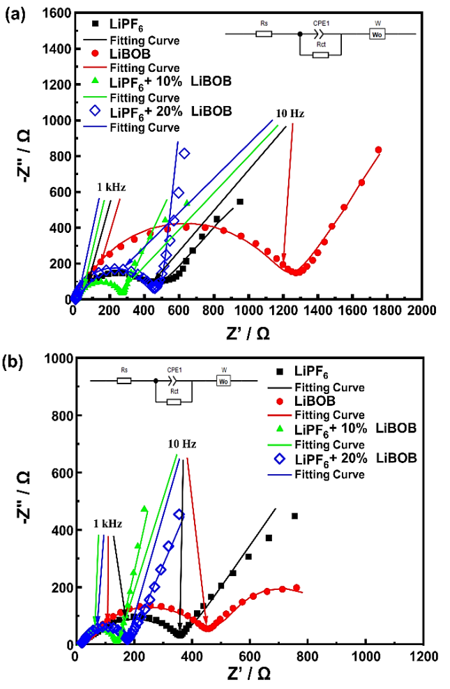
Figure 7 The Nyquist plot with fitting curve of the half-cell (a) before the cycle and (b) after 25 cycles of the rate capability test.
Table 3 The detailed resistance values of the half-cell before the cycle and after 25 cycles of the rate capability test.
| Sample | Before Cycle | After Cycle | ||
|---|---|---|---|---|
| Rs (Ω) | Rct (Ω) | Rs (Ω) | Rct (Ω) | |
| LiPF6 | 3.74 | 429.21 | 18.53 | 336.81 |
| LiBOB | 13.30 | 1203.80 | 35.46 | 405.28 |
| LiPF6 + 10% LiBOB | 10.52 | 253.27 | 12.82 | 129.26 |
| LiPF6 + 20% LiBOB | 2.13 | 393.41 | 17.52 | 157.34 |
After 25 cycles, the solution resistance of the half-cell regularly increases, while the interfacial resistance, on the other hand, decreases steadily, which was observed for all electrolyte samples. Throughout the cycles, the decomposition of the electrolyte component will occur continuously, especially in cases of high-voltage operation where these phenomena will become more severe and finally result in the value of
In contrast, the LiPF6 with 10% LiBOB still possesses the smallest charge transfer resistance of only 129.26 Ω and even the smallest solution resistance of 12.82 Ω, indicating a faster Li-ion diffusion to the spinel structure of the LNMO cathode in the insertion/extraction processes. On the other hand, LiBOB baseline electrolytes have the most significant reduction in charge transfer resistance before and after the cycle, confirming the previous research (Abeywardana et al., 2019). Compared to LiPF6 with 10% LiBOB, the 20% LiBOB addition also shows a greater reduction in charge transfer resistance, indicating the positive effect of CEI formation to increase the conductivity of the half-cell (Cheng et al., 2021; Dong et al., 2017; Wang et al., 2018). But still, in general, the proper amount with only 10% LiBOB addition can serve better electrochemical performance in terms of rate capability and specific capacity by easily accommodating Li-ion migration between Li-metal and LNMO cathode.
4. Conclusions
The electrochemical performances of LiPF6/LiBOB mixed salt electrolytes at a certain LiBOB ratio have been studied based on the specific capacity and rate capability. Adding 10% and 20% of LiBOB in LIPF6 electrolytes demonstrates better properties than their baseline electrolyte in the Li//electrolytes/LNMO cells. LiPF6/LiBOB mixed salt electrolyte showed a higher ionic conductivity of up to 0.129 mS cm-1 and a better stability window of 4.1 V (vs. Li/Li+) compared to 3.4 V (vs. Li/Li+) for the LiPF6 baseline electrolyte. These results were assumed to be due to the contribution of a protecting CEI layer formation to inhibit the oxidation of carbonate solvents and prevent the loss of active material. However, there is an inclining trend when the addition of LiBOB is too large, in which there is a tendency to be similar to the LiBOB baseline electrolyte. LiPF6 electrolytes with 20% LiBOB performed poorer electrochemical performances than those with only 10% LiBOB, with decreased specific capacity and plateau area and increased charge transfer resistance. The differential capacity study supported these results by showing lower oxidation and reduction peaks even in the absence of voltage shifting, indicating the need for an optimal amount of LiBOB content. Finally, mixed salt containing 10% LiBOB showed the best electrochemical performance with a stable rate capability of up to 1C and a high discharge capacity of up to 133.5 mAh g-1. These results indicate that adding LiBOB in LiPF6 electrolytes has a certain optimal amount for achieving excellent synergistic effects of LiBOB surface-forming ability to optimize the performance of LNMO cathodes with a significant specific capacity at high potentials and better rate capability at high current rates for the next-generation 5 V class LIBs.

