


 nueva página del texto (beta)
 Inglés (pdf)
 Artículo en XML
 Referencias del artículo
 Enviar artículo por email
 Citado por SciELO
  Similares en
SciELO
Similares en
SciELO 
 Permalink
1. Introduction
Synthetic fiber-reinforced polymer composites, especially carbon fiber-reinforced polymers (CFRPs) and glass fiber-reinforced polymers (GFRPs), have widely been used to fabricate various products, such as those of household appliance, casing for electrical and electronic products, sport and leisure goods, wind turbine components as well as ground, marine and air transportation vehicle. Besides their advantages such as higher specific strength and specific modulus and ease of manufacturing compared to conventional metals, they raise problems related to environmental pollution due to dumping of their post-service products. The use of natural fiber for reinforcing material to replace synthetic fiber in producing fiber-reinforced composite materials may reduce such problems because they are biodegradable (Fowler et al., 2006).
Arenga Pinnata (sugar palm) fiber (SPF) is an example of natural fiber that can be used for reinforcement in producing composite materials. As reinforcing materials, the SPF will contribute to the mechanical properties of the composite materials being produced. Other factors contributing to the properties of composite materials include fiber geometry and dimensions, fiber orientation and fiber content. Among the weaknesses of natural fibers including SPF are their size, geometry, chemical composition, and properties that depend on the place and climate where they are grown, as well as the age and the season when they are harvested, and how they are extracted.
Sugar palm plantations can be found in different regions of Indonesia. They are spread over 14 provinces, i.e., Papua, Maluku, Northern Maluku, Banten, Northern Sulawesi, Southern Sulawesi, South-eastern Sulawesi, Bengkulu, Southern Kalimantan, and Aceh covering approximately 70,000 ha of area. Sugar palm stem products have not been optimally utilized in Indonesia, either of from their food product or parts of stem for structural materials.
Misri et al. (2010) investigated the mechanical properties of woven SPF/EGF/unsaturated polyester prepared for small boat manufacturing. The weight fraction of the total fiber was low, 18%. They found that the tensile properties of SPF/polyester composite increased with the incorporation of EGF. The compression molding technique combined with hand lay-up technique was suitable for small boat manufacturing. The tensile strength, Young’s modulus and failure strain of SPF/polyester composites are 17-23 MPa, 1.5865 GPa and 1.65%, respectively. The tensile strength, Young’s modulus and failure strain was found to increase by 58.8-87%, 16.01% and 67.27%, respectively, due to the hybridization effect. Sapuan and Bachtiar (2012) used SPF as reinforcement in separate way with high impact polystyrene (HIPS) matrix. They cut SPF into fine chopped fiber passing through mesh 50 and 30. They reported that the tensile strength, 19.3 MPa, was slightly lower, and Young’s modulus, 1.706 GPa, was slightly higher than those previously reported by Misri et al. (2010), although it was at significantly higher fiber content, 30%.
Ilyas et al. (2019) investigated fully bio-degradable composite, where sugar palm starch (SPS) was reinforced with different loading of sugar palm nanofiber cellulose (SPNFC). Their specimens were very thin, ∼123.0-124.1 μm thick. Their SPNFC was fine, where the diameter was 5.5 nm and a few micrometers long. They found that incorporation of SPNFC into SPS significantly increased the tensile properties of the resulting composites. They found that the tensile strength increased from 4.80 to 10.68 MPa, the Young’s modulus increased from 53.57 to 121.26 MPa, and the failure strain is 1.423%. The Fourier-transform infrared (FTIR) spectroscopy analysis showed that good compatibility between the SPS and SPNFCs, and the presence of intermolecular hydrogen bonds are responsible for such increase. Although the mechanical properties are low compared to those previously reported (241.93 MPa, 3.07 GPa, and 20.62-23.09 %, respectively) (Ishak et al., 2013), their composites are fully degradable.
Different efforts have been conducted to produce SPF-reinforced polymer composites, where different polymers have also been utilized as matrix. Misri et al. (2010) improved tensile properties of SPF/polyester composite by incorporating EGF with SPF. Sapuan and Bachtiar (2012) used finely chopped SPF to reinforce HIPS and found that there is no significant increase in tensile properties of their composites compared to those of pure HIPS matrix.
Bai et al. (1999) reported that sisal/epoxy composite beams failed by fiber-matrix interfacial debonding combined with micro-fibril integrity degradation, where composite failure was initiated at the tensile face of the beam, i.e., the bottom face of simply supported beams whose midspan undergoing downward deflection. Sudarisman et al. (2015) reported that flexural failure of bamboo fiber/epoxy composite beams was initiated at their tensile face.
It can be concluded that matrix-fiber compatibility, fiber architecture and stacking sequence can affect the mechanical properties of the composite being produced. In addition, most natural fiber composite beams initially failed at their tensile face. The current work deals with the partial substitution of EGF for SPF in the tensile side of SPF composite beams to improve flexural properties of SPF/polyester composite beams.
2. Materials and methods
2.1. Research variables
There are two independent variables, four dependent variables, and one controlled variable in this research. The two independent variables are hybrid ratio (r h) and span-to-depth ratio (S/d).
Where V f-g and V f-tot are volume fraction of EGF and volume fraction of all fillers combined, respectively. V f-g is represented by the number of EGF layers 0, 1, 2 and 8 which results in r h = 0.00, ∼0.13, ∼0.26 and 1.00, respectively. The span-to-depth ratio being used are ∼20 and ∼30.
The dependent variables are flexural properties consisting of flexural strength, flexural modulus, flexural failure strain, and flexural failure modes. The controlled variable was total fiber content which was kept constant at ∼21 vol%. Considering the volume of EGF depends on the number of its layer, cannot be freely selected, the volume of SPF and polyester being used is then calculated based on that of the EGF being used. The composition of the constituent material is presented in Table 1.
2.2. Materials
SPF obtained from local sugar palm stem was individually pulled out of its mesh, cleaned from debris, and washed using plain water. Following this, the SPF was soaked in 5 wt% NaOH solution for 2 hours and neutralized by soaking it in plain water for 48 hours where every 6 hours it was manually stirred, and the water was changed. Next, the SPF was rinsed in flowing water, drained, and slowly dried at room temperature to prevent any fine surface cracks. The details of this procedure been published elsewhere (Sudarisman et al., 2017). The dry SPF was finally chopped into 10 mm long (Fig. 1 (a)) using a sharp scissor.
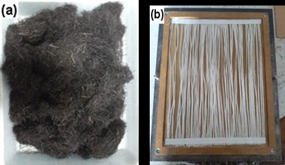
The EGF was obtained from the local market in the form of woven fabric. The weft and wrap were separated and kept in unidirectional pattern. The matrix being used is 268 BQTN unwaxed polyester, along with MEKP catalyst. The woven EGF, polyester resin and catalyst were obtained from PT Justus Kimia Raya. The properties of the constituent materials are presented in Table 2.
Table 2 Properties of constituent materials.
| Properties | Constituent materials | ||
| SPF1 | E-glass2 | Poly-ester3 | |
| Density (g/cm3) | 1.43 | 2.55-2.60 | 1.13 |
| Diameter (mm) | 0.168 | 0.012-0.023 | N/A |
| Tensile strength (MPa) | 173.9 | 2800 | 29.4 |
| Tensile modulus (GPa) | 3.8 | 86 | 2-4.5 |
| Tensile failure strain (%) | 12.8 | 2.2-2.5 | 3.2 |
1Sudarisman et al. (2015). 2Sudarisman et al. (2017); ASM, 2007; Dong, (2019). 3Dong et al. (2013); Ilankeeran et al. (2012); Safety Data Sheet (2019).
2.3. Composite plate fabrication
Four composite plates of different hybrid ratios were fabricated. The plates were fabricated by means of cold press mold where the fibers were placed by hand lay-up technique. The unidirectional EGF lay-up is shown in Fig. 1 (b). The 0 and 8 EGF layers, meaning chopped SPF/polyester composite and unidirectional EGF/polyester composite, respectively, are used as references. Fig. 2 shows two sheets of composite plate panels of different hybrid ratios.
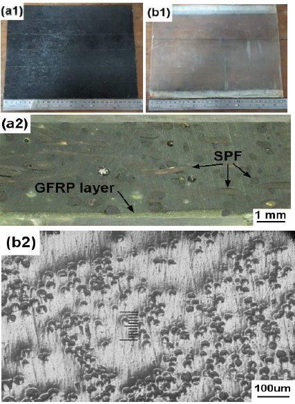
Figure 2 Composite plate panels: (a1) r h = 0.13 i.e., a plate with one layer of unidirectional EGF, (a2) r h = 0.13 - longitudinal side view, (b1) r h = 1.00 i.e., a unidirectional EGF/polyester plate, (b2) r h = 1.00 - cross-sectional side view.
It can be seen in Fig. 2 (a2) that the chopped SPF is considered evenly distributed in the upper layer. In the lower part, the GFRP layer shows inhomogeneous thickness. Unlike dry or prepreg lay-up that results in a more homogeneous layer thickness (Dong et al., 2013), wet lay-up technique commonly produces inhomogeneous layer.
2.4. Specimen preparation
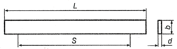
Specimens were cut from composite plate panels using a SiC-tipped circular blade rotating at ∼6000 rpm. The chopped SPF/polyester system was placed on the compression side, and the unidirectional EGF/polyester system was placed on the tension side. Fig. 3 shows the geometry of the specimens prepared for flexural testing in accordance with the ASTM D790 standards (ASM, 2007).
2.5. Flexural testing
Beam specimens were loaded in three-point bending configuration at a strain rate of ∼1% per minute. As recommended by Dong (2019) the stronger unidirectional EGF/polyester composite layer was placed in tension side, while the weaker natural fiber-reinforced polymer composite (NFRPC) layer was placed in the compressive side. The depth of the beam specimens was the thickness of the composite plate, ∼3.2 mm, resulting in support spans of 64 mm and 96 mm for S/d of ∼20 and ∼30, respectively. The test was performed at room temperature using a RetroLine test Control II Zwick/Roell universal testing machine possessing maximum load capacity of 20 kN. The magnitudes of flexural strength, strain at maximum stress and modulus were then calculated using Eqs. (2), (3) and (4), respectively (ASM, 2007).
Where F, S, b, d, and D are the magnitude of the maximum load (N), support span (mm), beam width (mm), beam depth (mm), mid-point deflection (mm), respectively. While m = (F/(D is the slope of the tangent of initial strain line of F-D plot (N/mm). At least five specimens were evaluated, and the results presented here are their average values.
2.6. Image capturing
After being evaluated until failure, a representative specimen from each variation was randomly selected and prepared for micrograph capturing under an optical microscope. Each pair of photo micrographs and its F-D graph obtained from flexural test were closely observed to evaluate its failure mode.
3. Results and discussion
3.1. Stress-strain relation
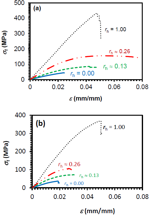
Unlike those of hybrid higher strength carbon fiber/ EGF/epoxy composites which exhibited almost linear σ-ε relation up to almost failure (Dong et al., 2013), hybrid SPF/ EGF/polyester, i.e., rh ≈ 0.13 and rh ≈ 0.26, (Fig. 4) shows small (∼0.005 mm/mm) linear portion of σ-ε relation, and further loading produced nonlinearity as can be seen in Fig. 4. The higher the rh, the longer the linear portion of the σ-ε plots. The linear σ-ε relation of the carbon fiber and EGF reinforcement (Ilankeeran et al., 2012), higher reinforcement tensile strength and higher Vf may be the cause of the difference in σ-ε relation pattern. The tensile strength of the fibers being used in the former are 3450 and 4900 MPa (Ilankeeran et al., 2012) while in the current work are σf-SPF = 173,9 MPa and σf-GF = 2800 MPa (Table 2). The Vf-tot being used in the former was varied at 44 to 49% compared to those employed in the current work Vf-tot = ∼21%. According to the rule of mixtures, the properties of the composites are more fiber-dominated at a higher Vf, while at a lower Vf, the composite properties are more matrix-dominated. In addition, Figs. 4(a) and (b) also indicate that the elastic modulus indicated by the slope of σf-εf plot increases with rh.
3.2. Flexural strength
The effect of hybrid ratio, r h, on flexural strength, σ f, at the two span-to-depth ratios are presented in Fig.5. It can be seen in Fig.5 that the increase of r h results in the increase of σf. In addition, σ f at S/d ∼20 was found higher (27.9-41.2 %) than that at S/d ∼30. Similar trend has previously been reported for hybrid carbon/EGF/epoxy composites (Dong et al., 2013). Larger positive hybrid effect can be observed at S/d ∼20 compared to that at S/d ∼30. Smaller r h resulted in a larger percentage of relative increase of flexural strength. At r h ∼0.13, the increase of flexural strength is ∼187% with respect to that at r h = 0.00. At r h ∼0.26, it is ∼53% with respect to that at r h ∼0.13 both for S/d ∼20 and S/d ∼30. This may be attributed to the farther relative position of the stronger fiber, the EGF, from the neutral axis of the beams.
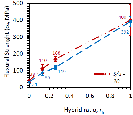
Flexural strength of SPF/polyester composite, r h = 0.00 (38 and 31 MPa at S/d = ∼20 and ∼30, respectively) was found comparable to that of the similar composite previously reported (38.906 MPa) by Sahari et al. (2011), although the V f in current work is lower. Compared to that of pineapple leaf fiber-reinforced polypropylene composite (12.67 MPa) at a comparable fiber content (Leao et al., 2010), the flexural strength of SPF/polyester composites found here is significantly higher. Higher tensile strength of the SPF used in the current work (Table 2) compared to that of the pineapple leaf fiber (126.6 MPa) previously reported by Arib et al. (2006) may be responsible for such result.
3.3. Strain at maximum stress
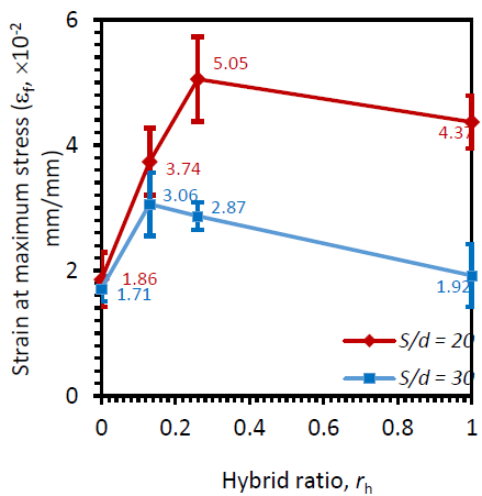
Figure 6 exhibits the effect of r h on flexural strain at maximum stress for the two different span-to-depth ratios, i.e., S/d ∼20 and S/d ∼30. Both plots show that the strain at maximum stress increases by the partial substitution of continuous EGF for chopped SPF at tension side. Both showed that the slope of the shorter beams, S/d ∼20, is slightly steeper than that of the longer one, S/d ∼30. Although failure strain of EGF is low, i.e., 2.2 - 2.5% E, R and D Glass Properties (2002) and will result in low failure strain of its polyester matrix composites, its incorporation with chopped SPF in the same matrix at low fiber content result in the increase in flexural strain at maximum stress. High failure strain of the SPF, i.e., 12.08% (Table 2), may be responsible for the increase of the strain at maximum stress of the resulted hybrid composite beams. Higher strain at maximum stress and higher failure strain materials will be valuable when the material is used for structures requiring energy absorption capacity. Such materials will be able to absorb larger amounts of energy at the same strength. Thus, by increasing both strength and strain at maximum stress, the amount of energy being absorbed will be even larger. In addition, from the safety point of view, there will be more available time for evacuation of dwellers between the initial observable deformation until the first crack occurs.
3.4. Flexural modulus
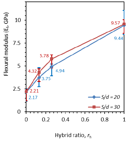
The effect of hybrid ratio on flexural modulus is presented in Fig. 7. It shows similar trends as demonstrated by flexural strength and strain at maximum stress for both S/d ≈ 20 and S/d ≈ 30. It can also be seen that a higher relative increase in flexural modulus was obtained at fewer amount of EGF substitution for SPF, shown by steeper slope of the plot. This is in line with previous finding reported by Dong and Davies (2015) for hybrid CF/EGF/Epoxy composites.
3.5. Failure modes
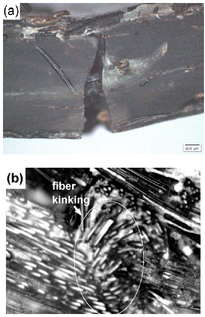
In addition to hybrid fiber composites, the current work also fabricated both SPF/polyester composite beams and GFRP composite beams for references. Their fractographic images are presented in Fig. 8 (a) and 8(b). The SPF/polyester composite beam (Fig. 8 (a)) shows the same failure modes as previously reported for sisal fiber/epoxy and bamboo fiber/epoxy composites (Bai et al., 1999; Sudarisman et al., 2015), and even with that of blended chopped SPF/EGF-reinforced PLA hybrid composites (Sherwani et al., 2021). To the contrary, the GFRP composite beam (Fig. 8 (b)) shows fiber micro-buckling followed by kinking and crushing in its compressive face.
Partial substitution of EGF for SPF in the weaker side, i.e., tensile side, of the beam resulted in the change in failure mode as can be seen in Fig. 9. In addition, a significant increase in its flexural properties can also be obtained as demonstrated by Figs. 5, 6 and 7.
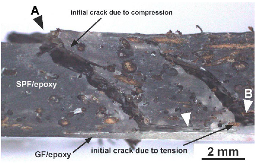
Unlike the failure mode of SPF/polyester or EGF/polyester composite beams shown in Fig. 8, failure was initiated by delamination (white arrow) at its interface of SPF/polyester-EGF/polyester layers. This was followed by an inclined crack due to tension at its tensile side on the right side of the beam (point A). Next, an inclined crack due to compression in the upper part of the beam occurred on the left side (point B). The delamination was caused by high interlaminar shear stress generated in that interface due to significant mismatch in mechanical properties between the two adjacent layers (Balasubramani et al., 2018). The higher the interlaminar shear stress at the interface, the more easily a delamination will occur (Lu & Liu, 1992).
The separation between the stronger EGF lamina and the weaker SPF/polyester lamina would initiate crack at the tension side of the weaker lamina, i.e., lower face of the SPF/polyester system, propagated upward as shown on the right side (point A) of Fig. 9. Following this, the upper face will experience compressive crushing causing inclined crack at a similar angle as that of the first crack.
After the load was removed, the beams being evaluated would undergo spring back, and both the inclined cracks show wider separation where the crack was initiated. Soni and Kim (1986) also observed similar phenomenon for carbon-carbon laminated composite where failure was initiated by delamination at the interface of the stronger 0( and the weaker +30( fiber orientations, followed by inclined crack in the weaker lamina.
4. Conclusions
SPF/polyester, EGF/polyester and hybrid SPF/EGF/polyester composites were successfully fabricated and evaluated. It was found that partial substitution of EGF for SPF at the tension face of composite beams produced significant increase in flexural strength, flexural modulus, and strain at maximum stress. The slope of σf-εf plots was steeper when the amount of substitution is fewer. All the hybrid composite samples exhibited initial delamination failure at the SPF/polyester-EGF/polyester interface, while the compressive face did not show any failure initiation, indicating that compressive side was still considerably stronger than interlaminar shear strength. It is recommended that shear load bearers be implemented at this interface to further improve flexural properties of the beams.

