


 nueva página del texto (beta)
 Inglés (pdf)
 Artículo en XML
 Referencias del artículo
 Enviar artículo por email
 Citado por SciELO
  Similares en
SciELO
Similares en
SciELO 
 Permalink
1. Introduction
One of the global trends in the modern world is the search for ways of practical transition of countries to a new technological framework based on the principles of decarbonization of production and carbon neutrality under the Paris Climate Agreement (PCA) (Chen et al., 2017).
The Republic of Kazakhstan is now positioned in the world as a country with a fast-growing economy, rich in natural resource potential, which provides high rates of economic growth. Since independence, Kazakhstan has launched a number of global initiatives for the transition to sustainable green development, such as the establishment of the first National Environmental Centre for Sustainable Development in Asia and the Pacific (1999), the Regional Environmental Centre for Central Asia (2000), the Coordination Centre for Climate Change, which are functioning successfully today and contribute to the progress of our country towards sustainable, low-carbon development (Abdullayev et al., 2017).
To study the national potential of decarbonization in the light of the implementation of the tasks set by the President of the Republic of Kazakhstan K.K. Tokayev to achieve carbon neutrality by 2060. For our country, the transition to low-carbon development and decarbonization of the economy is a serious and responsible challenge, requiring widespread measures in all areas of technological modernization of the national economy and its extractive sectors. The Ministry of Ecology, Geology and Natural Resources, with the support of the German Government, has developed a draft concept of low-carbon development of the Republic of Kazakhstan until 2050 (CLCD), which is based on the existing strategic documents, such as the long-term strategy "Kazakhstan-2050," the concept for the transition of the Republic of Kazakhstan to a green economy "and the strategic development plan of the Republic of Kazakhstan until 2025. It should be noted that the draft CLCD of the Republic of Kazakhstan, as well as the project ONUV (defined national contributions in the field of emission reduction), contains a set of measures of "green" transformation and "deep" decarbonization until 2050 (Abdullayev et al., 2017).
The success of the country's transition to low-carbon development depends on the understanding and support of the entire Kazakh society and the Kazakh National Research Technical University named after K.I. Satpayev. At the department of technological machines and transport, designs of devices for producing hydrogen and oxygen from water were developed, a prototype of the Citroen-5 car, 2003, 2.0-liter volume on hydrogen and gasoline was tested.
2. International experience of hydrogen production and use prospects for development of hydrogen energy
In 2020, the COVID-19 pandemic revolutionized the global economy and energy markets. Last year, global GDP declined by 3.5%, and primary energy consumption in the world fell by 5.4%. Widespread restrictions on movement to combat the spread of the pandemic have led, inter alia, to a sharp reduction in motor fuel consumption, which has resulted more broadly in a significant decrease in the demand for petroleum products (including crude oil and gas condensate, which are used for their production). Global demand for liquid hydrocarbons in 2020 fell by about 11%, and this decline amounted to more than 60% of the total reduction in primary energy consumption in the world in 2019. After oil demand, coal consumption fell by 4.9% in 2020. Demand for natural gas decreased moderately - by 2.7%. At the same time, the consumption of nuclear power decreased by 4.1%, and the demand for hydroelectric power and renewable energy increased. In general, in 2020, global demand for electricity decreased by 1.2%.
Hydrogen energy is a driver of the 21st century economy, capable of reviving the energy market in the transition to low-carbon or carbon-free fuels (Kudesia & Bisen, 2016). The number of progressive projects using hydrogen in the field of large and distributed energy, energy storage and all types of transport, from cars to aircraft and naval vessels, tends to increase, which will allow Kazakhstan to make a technological breakthrough in a significantly short period of time and, contrary to the forecasts of critics, to equal the progressive OECD countries. The current state and prospects for the development of hydrogen energy suggest that special attention should be paid to the following areas in the development of the national hydrogen strategy of the Republic of Kazakhstan:
1) creation of hydrogen production facilities, including through diversification of the oil and gas sector and power plants with excess/" failures "of capacity (Ekibastuz GRES, MAEK).
2) development of infrastructure for the delivery and storage of hydrogen, including the capabilities of existing gas transportation facilities.
3) production of transport on hydrogen fuel cells.
4) production of fuel cells of various capacities for transport and local power supply of areas and facilities remote from centralized energy infrastructure.
5) measures to stimulate the demand for hydrogen transport, including the regulatory framework for supporting the production and consumption of hydrogen.
6) conducting research and development in the field of hydrogen energy, including the creation of new materials for the storage of hydrogen and the production of fuel cells.
7) international cooperation in the field of hydrogen energy, including technological regulation and standardization.
The development of hydrogen energy will allow to realize the advantages of Kazakhstan and diversify the hydrocarbon sector, provide a leading transformation of the economy into a new technological way, and obtain large-scale benefits necessary for the dynamic socio-economic development of the country.
2.1. ICE with hydrogen fuel
Many car owners are looking for ways to save fuel. A hydrogen generator for a car will radically solve this issue.
The main technical reason, which is an insurmountable obstacle to the use of hydrogen as a fuel for cars, was the inability to fit enough gas on the vehicle (Woo et al., 2009). The size of the hydrogen fuel tank will be comparable to the parameters of the car itself. Large explosion hazard of gas should exclude the possibility of the slightest leakage. In liquid form, a cryogenic plant is required (Figure 1). This method is also not feasible by car.
Today, hydrogen generators are gaining popularity among motorists. However, this is not exactly what was discussed above. By electrolysis, water turns into the so-called brown gas, which is added to the fuel mixture. The main task that this gas solves is the complete combustion of fuel. This serves to increase power and reduce fuel consumption by a decent percentage. Some mechanics managed to achieve savings of 40%.
The surface area of the electrodes is crucial in the quantitative gas output. Under the influence of electric current, the water molecule begins to decompose into two hydrogen atoms and one oxygen. Such a gas mixture produces almost 4 times more energy during combustion than during combustion of molecular hydrogen (Kleemann et al., 2004). Therefore, the use of this gas in internal combustion engines leads to more efficient combustion of the fuel mixture, reduces the number of harmful emissions into the atmosphere, increases power and reduces the amount of spent fuel.
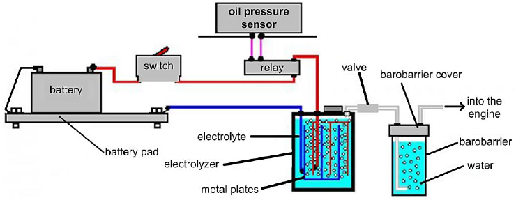
A hydrogen generator for a car can be bought from sellers who put on stream the assembly and installation of such systems. Today there are many such proposals. But you can assemble such a system yourself - there is nothing complex in it. It consists of several simple elements connected in one whole:
2.2. Reactor
The amount of brown gas produced depends on the area of the electrodes and their material. If copper or iron plates are used as electrodes, then the reactor will not be able to operate for a long time due to the rapid destruction of the plates. The use of titanium sheets is ideal. However, their use increases the cost of assembling the unit several times. The use of high alloy stainless steel plates is considered optimal.
2.3. Required performance
To really save fuel, a hydrogen generator for a car must generate gas every minute at a rate of 1 liter per 1000 engine displacement. Based on these requirements, the number of plates for the reactor is selected (Figure 2). To increase the surface of the electrodes, it is necessary to treat the surface with sandpaper in the perpendicular direction. This treatment is extremely important - it will increase the working area and avoid the "sticking" of gas bubbles to the surface.
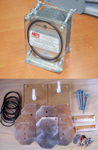
The latter leads to insulation of the electrode from liquid and does not prevent normal electrolysis. Do not also forget that for the normal operation of the cell, the water must be alkaline. The catalyst may be conventional soda.
2.4. Current regulator
A hydrogen generator on a car during operation increases its performance. This is due to the release of heat during the electrolysis reaction. The reactor fluid is heated, and the process is much more intense. A current regulator is used to control the reaction (Figure 3).
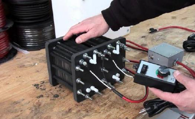
If you do not lower it, just boiling water may occur, and the reactor will stop delivering brown gas. A special controller that controls the operation of the reactor allows you to change the capacity with an increase in RPM. Carburetor models are equipped with a controller with a regular switch of two modes of operation: Route and City (de Souza Campos et al., 2019).
This modern hydrogen technology makes it possible to reduce fuel consumption by 20-60 percent, providing a significant reduction in emissions of the following substances:
2.5. Determination of the effectiveness of potassium hydroxide concentration (KOH)
On a high-speed highway, when using a hydrogen generator, when the concentration of potassium hydroxide is 35 g/l, fuel consumption with hydrogen is 6.5 liters per 109 km, when the hydrogen generator is turned off, fuel consumption without hydrogen is 6.1 liters per 94 km, relative fuel economy, (GwithHG - GwithoutHG)/GwithoutHG = 8.4%.
On a high-speed highway, when using a hydrogen generator, when the concentration of potassium hydroxide is 50 g/ l, fuel consumption with hydrogen is 4.2 liters per 103 km, when the hydrogen generator is turned off, fuel consumption without hydrogen is 7.45 liters per 103 km, relative fuel economy, (GwithHG - GwithoutHG)/GwithoutHG = 43.6%.
In urban conditions, when using a hydrogen generator, when the concentration of potassium hydroxide is 50 g / l, fuel consumption with hydrogen is 57 liters per 495.3 km, when the hydrogen generator is turned off, fuel consumption without hydrogen is 65 liters per 445 km, relative fuel economy, (GwithHG - GwithoutHG)/GwithoutHG = 21.2%.
Therefore, the addition of hydrogen can reduce fuel consumption, and with an increase in the concentration of coke (30-50%), fuel consumption decreases (8,4%-43,6%).
3. Hydrogen generator for internal combustion engine
Useful models relate to the field of alternative energy and can be used in internal combustion engines of any type of vehicles. The technical result is the presence of a hydrogen generator design for an internal combustion engine (ICE), which ensures the complete combustion of the fuel mixture with a sharp decrease in SO2 and NOx on the exhaust, fuel economy by 10-30 percent, engine power increase to 25%.
A low ampere cell for producing hydrogen and oxygen from water is known [RF Patent 2227817. Published 27.04.2004 IPC C25B1/04 C25B9/06], containing a conical body made of conductive material and acting as a cathode, additional conical electrodes, a conical cover made of conductive material, acting as an anode. Cylindrical bases of housing, additional electrodes and covers have annular recesses for arrangement of dielectric ring. Housing, additional electrodes and cover are connected by bolts inserted into holes of cylindrical bases of housing, additional electrodes, and cover. Insulation between anode, additional electrodes and cathode is provided by dielectric rings, dielectric washers, and dielectric bushings. Solution is fed into interelectrode space through channel from reservoir. Gases are discharged through the nozzle (de Souza Campos et al., 2019).
The conical shape of the electrodes creates conditions for the polarization of solution ions and water molecules, as a result of which positive potentials appear on the anode, and negative potentials appear on the cathode even before the cell is included in the electric network and the process of gas release continues after the cell is disconnected from the network. Due to this, the energy consumption for the process of decomposing water into hydrogen and oxygen is significantly reduced.
A disadvantage of the said invention is that in the production of hydrogen and oxygen there is no device for controlling the dissociation rate of water molecules depending on the mode of operation of the ICE.
The technical task is energy-efficient production of hydrogen and oxygen by low ampere electrolytic decomposition of water and synchronization of hydrogen generator performance with ICE operation mode.
The objective is achieved by, that the hydrogen generator for ICE includes one or several electrolytic cells for obtaining hydrogen and oxygen from water or electrolyte with total capacity equal to not less than the highest consumption of gas (hydrogen and oxygen) of ICE. Branch pipes of all cells for transportation of received gases are connected together and then gas is supplied to ICE through electric valve, pressure regulator and water gate (Benajes et al., 2014).
With a decrease in the speed or cessation of consumption of non-nuclear energy (brown gas) of ICE, the pressure in the electrolytic cells of the generator increases and displaces water or electrolyte, freeing the interelectrode space into the reservoir. At the same time, the gas generation speed decreases or completely stops in accordance with the mode of operation of the internal combustion engine. When the rate of hydrogen consumption exceeds the rate of its formation, the gas pressure in the generator nozzle decreases, which leads to the flow of liquid reagent from the tank to the interelectrode space. This, in turn, leads to an increase in the surface area of contact of the liquid reactant with the electrodes and an increase in the volume of gas released. And thus, the required volume of gas is maintained to supply the ICE.
Control of the rate of NMV release in such a generator occurs automatically, without human participation, depending on the rate of ICE gas consumption.
4. The essence of the utility model is explained in the figure
The hydrogen generator for ICE (Figure 4) consists of one or several electrolytic cells (on nothing one cell is shown), containing conic building 1 with the flat cylindrical basis 2 made of conducting material and serving as the cathode, the additional conic electrodes 3 made of conducting material with axial openings in tops of cones (on nothing. shows one additional electrode) and cylindrical bases 4, a conical cover 5 with a flat cylindrical base 6 made of a conductive material and acting as an anode. Cylindrical bases of housing, additional electrodes and covers have annular recesses for arrangement of dielectric rings 7. Housing 1, electrodes 3 and cover 5 are connected by bolts 8 inserted into holes of cylindrical bases of housing, additional electrodes, and cover. Insulation between anode, internal electrodes and cathode is provided by dielectric rings 7, dielectric washers 9 and dielectric bushings 10. The solution is fed into the interelectrode space through passage 11 from vessel 12. The gases exit through the branch pipe 13 and are supplied to the internal combustion engine via an electric valve 14 regulating the volume of gas supplied, a pressure regulator 15 and a water gate 16. The container 12 has at its top a safety valve 17 and a check valve 18.
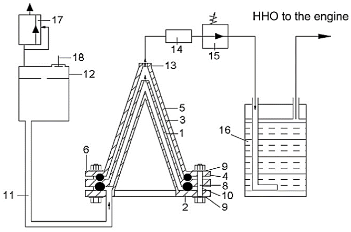
The internal combustion engine hydrogen generator operates as follows. The electrolytic solution is poured into vessel 12 to a predetermined level. The cell is connected to the DC network. Voltage corresponding to 1.6-2.2 Volts per pair of electrodes is set (Benajes et al., 2014). The current intensity depends little on the area of the anode, cathode and additional electrodes and is close to 0.02 A.
A few minutes after the generator cells are connected to the electric network of the vehicle, the active emission of gases begins. Before starting the internal combustion engine of the vehicle, an electric valve 14 is opened, and gas is supplied to the internal combustion engine supply system through the pressure controller 15, which maintains the constant gas pressure downstream and the water gate 16. Water seal 16 prevents the gas combustion flame front from spreading from the ICE to the generator (Wang et al., 2012). The overpressure in the container 12 above the liquid is controlled by safety valve 17 and the vacuum is compensated by check valve 18.
When the consumption of ICE hydrogen is reduced or stopped, the pressure in the electrolytic cells of the generator increases and displaces the electrolytic liquid from the space between the electrodes 1 and 2. At the same time, the gas generation speed decreases or completely stops in accordance with the mode of operation of the internal combustion engine. When ICE hydrogen consumption resumes, the gas pressure in the generator nozzle decreases, which leads to the flow of liquid reagent from the tank back to the interelectrode space. This, in turn, leads to an increase in the surface area of contact of the liquid reactant with the electrodes and an increase in the velocity of the released gas. Thus, the rate of hydrogen release in the generator is controlled automatically, without human involvement, depending on the rate of consumption of ICE gas.
The technical result - a hydrogen generator for ICE allows low-ampere electrolytic decomposition of water into hydrogen and oxygen to automatically control the rate of generation of non-nuclear energy synchronously with the mode of ICE operation.
Conclusions
Useful model refers to the field of alternative energy and can be used in the power system of internal combustion engines (ICE). hydrogen generator for ICE, which includes reservoir for electrolyte or water, electrolytic cells (one or more), with housing and electrodes of conical shape and with cylindrical base, at the same time base of housing has channel for supply of solution to interelectrode chambers, branch pipe for gas outlet is in upper part of cover cone. Housing, additional electrodes and cover are connected by bolts inserted into holes of cylindrical bases of housing, additional electrodes, and cover. Insulation between anode, additional electrodes and cathode is provided by dielectric rings, dielectric washers, and dielectric bushings. Solution is fed into interelectrode space through channel from reservoir. Gases exit through the branch pipe and, passing through the electric valve, pressure regulator and water gate, enter the internal combustion engine supply system.
The technical result is low-ampere electrolytic decomposition of water into hydrogen and oxygen and automatic synchronization of hydrogen release rate with internal combustion engine operation mode.
A generator for producing HPO gas for an internal combustion engine, comprising an electrolyte vessel; electrolytic cell, with a body and electrodes of conical shape and with a cylindrical base, wherein the housing base has a channel for supplying solution to the interelectrode chambers; gas outlet branch pipe is located in upper part of cover cone; differing in the outlet branch pipe is equipped with an electric valve, a pressure regulator and a water gate.
The generator according to claim 1, characterized in that the electrolyte tank is provided with safety and check valves.
Conflict of interest
The authors have no conflict of interest to declare.
Funding
The authors received no specific funding for this work.

