


 nueva página del texto (beta)
 Inglés (pdf)
 Artículo en XML
 Referencias del artículo
 Enviar artículo por email
 Citado por SciELO
  Similares en
SciELO
Similares en
SciELO 
 Permalink
Introduction
Composite materials are very important for aeronautic, automotive, and energy industries today, due to their capability to modify their mechanical, chemical, and electrical properties in a personalized way to reach a specific application (Askeland et al., 2011). However, metals are the main used materials, they occupy more than 80 percent of the structural mass of an aircraft (Mouritz, 2012); aluminum is used due to its low weight, accessibility, effortless manufacturing, ductility, and fracture toughness, they are mainly used in the aircraft skin, lower brim and control panels (Campbell, 2006). Titanium helps in motor parts, holding structures, and landing gears as it has high strength, fatigue, fracture, and corrosion resistance (Bhattacharjee et al., 2017). Talking about steel, it is limited to a total of 5-8 % of the structural weight, it is used only for critical structural components, and this to ensure the structural integrity as it has high strength resistance, high elastic module, and it can withstand fatigue, fracture and high temperatures (Bhat, 2018).
Currently, polymer composite materials are used in aerospace, and continuous fiber and sandwich-type composites are used the most (Jayakrishna et al., 2018). These materials are valuable by their low density instead of metals while maintaining high resistance and stiffness, fatigue resistance, corrosion resistance, and tolerability. On aircraft are popularly used in part of wings, fuselage, empennage, and control surfaces, while in launch vehicles have been used as propellant tanks framework (Henson, 2018).
Some studies around mechanical and thermal activity in composites were found, in which by increasing the fiber length over the thermal conductivity, it was observed that while longer the fiber, it provides thermal stability and increases the lifetime (Rezaei et al., 2008). Additionally, other research estimated the thermal conductivity of composites that contain heterogeneities (Yu et al., 2013). Studies around simulation were found, in which a thermo-mechanic model for delamination evaluation was done by applying thermal stresses (Goyal et al., 2015); a simulation about the reinforcement at a microstructural order, and the volumetric fraction to evaluate the thermal coefficient of conductivity dependence (Godar et al., 2016).
Recent advances declared the use of hybrid composites reinforced with glass, carbon and basalt fabric, where commonly methods were used; in this review, authors joined the study with unidirectional, multidirectional, and biaxial reinforcements (Matykiewicz, 2020). A research about filler-based composites demonstrated that hemp natural filler shows good crystallinity characteristics; the mix between the hemp and silver nanoparticles exposed the maximum tensile test at 32.03 MPa and a 1.00 W/mK thermal conductivity (Siva-Kumar et al., 2021). Keeping the same topic, authors developed a study using micro-bamboo filler plus graphene nanoplatelets, this composite reached a maximum ultimate tensile strength of 41.43 MPa at a crosshead speed of 3 mm/min (Gouda et al., 2020). Another one in the same direction, set the mix between mortar and date palm fiber, authors varied the date palm fiber weight from 0 % to 30 % on size length of 7 mm, they submitted the composites to a three-point mechanical test and proved that using 6 % of fiber concentration, the material will reach the maximum flexural strength (Benaniba et al., 2020).
Late progresses in modeling composites evidenced that while increasing the temperature by ΔT=40 K, the elastic modulus decreases for short fiber reinforcements in polymer composites, authors demonstrated this behavior by simulation and experimentally (Hao-Zeng et al., 2020). Other researchers developed the failure analysis of composites, authors used AS4 fibers and 3501 epoxy for their study, the temperature considered is about 30 °C; to achieve this investigation, they submitted the material to different strengths and evidenced that it will fail at 1067.95 MPa for a laminate orientation of [0° / ± 30° /90°] (Junjie et al., 2020). Also, finite element analysis was used to determine the thermo-mechanical properties of composites made of ZrO2, SiC and porous matrix, authors found more than 70 % of accuracy in thermal conductivity (Kamran & Sridhar, 2020).
The present work has studied the mechanical strain and thermal expansion behavior of a polymeric composite material, which is intended to be used in an aerospace fuselage for a reusable launch vehicle, considering a residual stress factor for each cycle. A tension test was selected to evaluate the material, this mechanical process has been modeled through MATLAB® software, followed by studying the effect of temperature and considering a residual stress analysis which was assumed will alter the mechanical properties of the material between subsequent tension test cycles. It is proposed the fabrication of this theoretical material through modeling different number of layers, as a laminated composite, this process was analyzed and carried out by Finite Element Method software with ANSYS®; finally, theoretical and numerical results were compared.
Composite material
Composite materials (CM) are the result of mixing two or more materials or phases, which combine their properties. The general classification of the CM is defined by the matrix type: metallic, ceramic or polymeric (Chung, 2010). Composites with the metallic matrix are usually reinforced with ceramic fibers, thus the matrix provides high-temperature resistance. Ceramic ones are typically reinforced with metallic fibers to raise the resistance. Finally, polymeric-type composites are the most common, they can be made for a specific purpose, and some of the applications are in the automotive and aerospace industry (Daniel & Ishai, 2006).
Here it’s modeled as a polymeric type CM which is formed by carbon-fiber 3K (JSA, 1986), acting as the fiber-reinforcement and epoxy resin S2040 (Epolyglas, 2019) as the matrix. These materials are proposed as the fibers have high elastic modulus and the matrix provide temperature resistance. Mechanical properties were studied through the rule of mixture, which establishes:
Were E and ν are the elastic modulus and the Poisson ratio; it is seen c, f and m in both, they are related to the composite’s fiber’s and matrix’s respectively; Vf and Vm correspond to the volume expressed in percentage for the fiber and matrix (Askeland et al., 2011).
This material is also submitted to a thermal gradient, it was followed by three different theories: beginning with the mixture’s theory, the dilatation coefficient can be calculated by:
Where
Where Gm is the matrix shear modulus (López, 2016). The last theory studied is Turner’s who wrote:
These theories were used to calculate the deformation caused by dilatation in the composite material; additionally, the results were analyzed and compared to understand the stress-strain relation of it under mechanical tests.
Methodology
It was submitted the composite material to a standardized tension test following ASTM D3039 (International, A., 2017), this test was analytically done, and it was obtained the maximum capacity load to withstand below the elastic limit, the maximum strain and stress. To focus on a reusable material, it was established that the process of charge-discharge should be done more than one time, consequently, residual stress is assumed to affect the stiffness of the material:
Where
This coefficient is assumed to directly impact on the Young’s modulus and the Poisson ratio from the second to the nth launch (L) as:
Modeling
The theoretical material was studied analytically by means of MATLAB®, in which it was modeled with different percentages of fiber to understand and select the most suitable for the purpose: 20, 40, 60, and 80 percentage of fiber were tested. All models were assumed to be in a configuration of 0°, considering that all fibers would be parallel to the applied force. In Figure 1, the mechanical behavior of each percentage is presented.
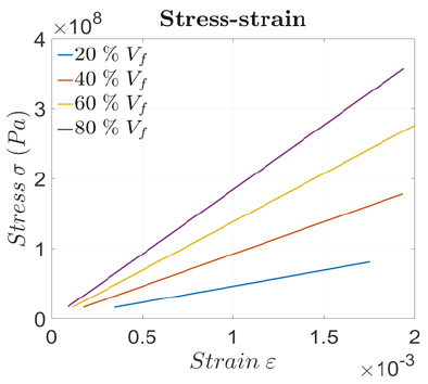
Figure 1 exposed that the best relation to use is between 40 and 80 of the fiber’s volume, however, for the next analysis, 60 % was selected and used. The option of 80 % was completely discarded, despite having ideal mechanical behavior, it is well known that manufacturing a polymeric composite material with this relation, it is unreliable due to the poor adhesive resistance between matrix and reinforcement, as it is a small quantity of the matrix percentage (Askeland et al., 2011).
From the first result, it was obtained the maximum load and the behavior over a reusable purpose, each time it began again, a factor of 0.85 was considered; it was calculated following the residual stress equation, where a value of 2 as a safety factor was considered. A similar process was done to study the material through axial loading and thermal activity, obtaining the maximum load, residual stress, and a number of possible cycles to be applied for a reusable purpose.
ANSYS® was used to understand a manufactured-like material, it was proposed to use 2, 4, and a maximum of 6 layers of carbon-fiber 3K; it was followed that this material had a specific thickness, hence, it could be manufactured in a proportion of 40-60 following the standards of ASTM. Each material was carried to a continuous axial load and numerically solved through ANSYS Structural®.
Results
This section presents the theoretical material modeled through MATLAB® and ANSYS®. Previously it was defined that 60 % of volumetric fiber fraction was the most suitable to study and even to manufacture, consequently, all the obtained results are in function of this value.
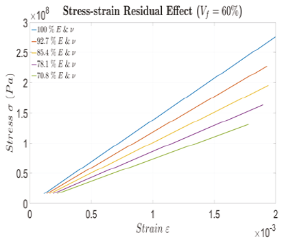
Beginning with a pure mechanical study, Figure 2 showed how the material behaves through a number of finite cycles. It was observed that the material could withstand about four cycles of the charge-discharge process, more than that, the material’s properties could be committed.
The next result was obtained by applying the three thermal theories previously mentioned, the material was submitted again to a continuous axial load but assuming 130 °C thermal difference activity (Ecker et al., 2019; 2018), the product is presented in Figure 3.
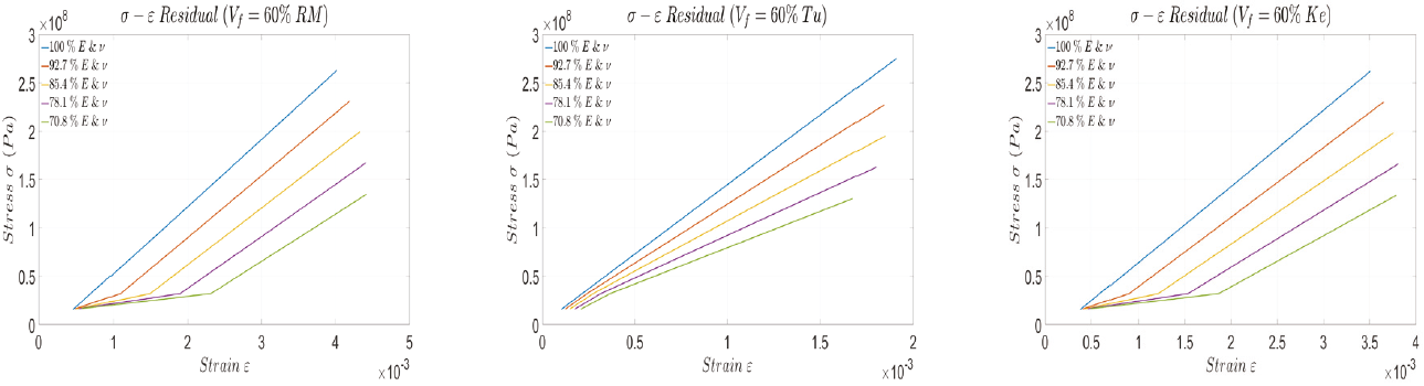
Figure 3 a) Composite material studied through Mixture Rule thermal model, b) Turner model, c) Kerner Model
Figure 3 displayed that the material can withstand the same four cycles of the charge-discharge process, but in the fourth, the material had a greater value of strain compared with pure axial load, this might be a problem in a possible application. All of them showed ideal behavior; for these events it was assumed that the material was isotropic.
From now on, the outcome will be obtained by modeling the manufactured-like material in ANSYS®, following the same methodology, beginning with the behavior of the axial load applied to the transversal cross-section of each of the models (Figure 4).
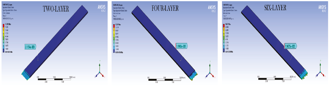
Figure 4 Axial load numerical solutions by ANSYS Structural®: a) two layers, b) four layers, c) six layers
These results showed the mechanical behavior of the different models. It is seen that the best relation was obtained in the four-layer model. Strain analysis is done and shown in Table 1, in which it is observed the relative error obtained from the theoretical material modeled in MATLAB®, taken as the real value, and ANSYS® modeling as the experimental. Relative error (e) and similarity (s) were defined as:
Table 1 Strain values and relative error for each of the n-layer material model
| n-layer | MATLAB® Strain | ANSYS® Strain | Relative error % |
|---|---|---|---|
| 0 | 0.001997 | ||
| 2 | 0.002115 | 5.89 | |
| 4 | 0.001990 | 0.32 | |
| 6 | 0.001963 | 1.7 |
Thermal activity was implemented in each of the n-layer materials; Figure 5 shows the Mixture Rule method behavior. In Tables 2, 3, and 4 are collocated all the strain analysis for each method calculating the relative error by comparing them as before. In the tables, these acronyms to establish which thermal coefficient theory were followed: Rule of Mixture (RM), Kernel (Ke), and Turner (Tu).
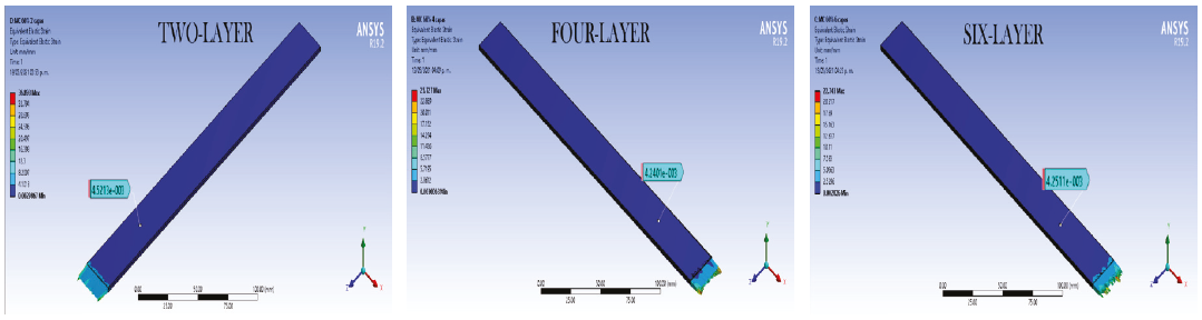
Figure 5 Axial load and thermal strains by Mixture Rule Model, a) two layers, b) four layers, c) six layers
Table 2 Strains values and relative errors considering thermal models in a two-layer material
| Thermal model | MATLAB® Strain | ANSYS® Strain | Relative error % |
|---|---|---|---|
| RM | 0.004255 | 0.004521 | 6.25 |
| Ke | 0.003688 | 0.003924 | 6.42 |
| Tu | 0.001906 | 0.002035 | 6.76 |
Table 3 Strains values and relative errors considering thermal models in four layers material
| Thermal model | MATLAB® Strain | ANSYS® Strain | Relative error % |
|---|---|---|---|
| RM | 0.004255 | 0.004240 | 0.35 |
| Ke | 0.003688 | 0.003686 | 0.05 |
| Tu | 0.001906 | 0.001900 | 0.29 |
Table 4 Strains values and relative errors considering thermal models in six layers material
| Thermal Model | MATLAB® Strain | ANSYS® Strain | Relative error % |
|---|---|---|---|
| RM | 0.004255 | 0.004251 | 0.09 |
| Ke | 0.003688 | 0.003623 | 1.75 |
| Tu | 0.001906 | 0.001883 | 1.22 |
It is observed that the strain results of the material numerically modeled have 93 % of similarity when compared to the assumption of a homogeneous material modeled in MATLAB®. It is seen that a two-layer material could achieve the reusable process.
Now, by solving a four-layer material, results seemed to be ideal, it can be observed that the similarity of the strain values were extremely close, by performing a relation between them, 99 % of precision was obtained. This configuration surely withstands at least three cycles.
By using a six-layer material, strain results evidenced less similarity than the four-layer studied before, it reached 98 % compared with the ideal material modeled in MATLAB®. Furthermore, this configuration can withstand all the processes of charge-discharge in a finite cycle application.
Conclusions
The theoretical composite material showed ideal mechanical properties, by modeling in MATLAB®, it was assumed that it should be isotropic, but after studying it as a manufactured-like material in ANSYS®, we realized that the material could behave as ideal, reaching a maximum of 99.95 % of similarity by comparing the strain results.

