


 nueva página del texto (beta)
 Inglés (pdf)
 Artículo en XML
 Referencias del artículo
 Enviar artículo por email
 Citado por SciELO
  Similares en
SciELO
Similares en
SciELO 
 Permalink
Introduction
Chromatography is a technique that is used in the characterization of complex mixtures, it allows to separate the individual components and determine their quantities according to their ability to distribute between a mobile phase, which contains the sample, and a stationary phase. When the mobile phase is a liquid, this technique is known as liquid chromatography or liquid chromatography (Freifelder, 1991).
Chromatography is used in a variety of fields, such as: Drugs, biochemistry, food products, chemical industry products, forensic chemistry, clinical medicine, among others. Particularly, in biotechnology it is commonly used to purify biological molecules, such as proteins, for medicines or other uses (Yong & Jun, 2017). It is based on the principle that molecules in a mixture are applied to a surface or solid and are separated by being differentially retained by the stationary phase while being moved with the help of a mobile phase (Coskun, 2016, Sheehan & O'Sullivan, 2003).
A chromatography fraction collector is a complementary piece of equipment in a chromatography system, it is responsible for accurately collecting each of the fractions recovered from a mixture. This equipment allows to eliminate the intervention of the user when making the change of container between samples and can be coupled to an endless number of chromatographic systems (Sharapin, 2000). Actual commercial collectors are versatile devices and require elementary knowledge for their handling, they can collect each sample or fraction taking as variables the volume, time, drop count, etc. (Coskun, 2016, Sheehan & O'Sullivan, 2003).
According to their structure, two main types of collectors can be identified, spiral and Cartesian. The characteristics of both are similar, their main difference is simply the way in which the samples are collected, since while the spiral collector is based on practically turning a container to change samples, the Cartesian type collector moves in two axes X and Y, that is, it can be located on a plane to work through plane coordinates and make movements more precisely.
Although a fraction collector has become a necessary resource for any lab where bioseparations are carried out, its presence is mainly limited by its high acquisition costs; since they are mostly imported and their supply in the national market is limited.
The cost of an automated fraction collector can vary depending on the model, brand, features and supplier, between 4,000 and 15,000 USD, and are thus not always available to budgetary constrained research and educational programs.
Conducting a literature review we found few works that present the design and construction of a fraction collector for liquid chromatography, one of them is the one developed by Caputo et al. (2019), in which they use LEGO MINDSTORMS pieces to develop a basic fraction collector.
This paper presents the design and construction of a Cartesian-type fraction collector for liquid chromatography. The collector CAD model is developed in Autodesk's FUSION360 software, where a stress and strain study is also carried out using finite element analysis, which allows ruling out any possible structural failure. Subsequently, the different components of the designed CAD model were built using 3D printing, which allows the construction of elements in a single piece and the use of accessible and appropriate materials for the application (Jorquera, 2016). The application of these manufacturing techniques allows to create a device that is both fully functional and accessible compared to commercial versions of similar equipment.
The developed system allows the automatic collection of fractions based on the time or number of samples, both established by the user. For this, the user interface and the control system are implemented on the Arduino uno development board. The user interface consists of an LCD screen and a set of buttons that allow the operation parameters to be established, and the control system is responsible for positioning of the head in the collection tube through the operation of two stepper motors.
The fraction collector was designed to meet a need of our institution. However, it is a versatile device and can be used in any experiment that requires the collection of samples, it can also be adapted to any specific need.
Development
Design
A Cartesian type design was chosen due to its accuracy and simpler implementation. The general specifications of the design are shown in Table 1. The selected material for the main structure is the aluminum profile, a material that is easy to work with and that offers excellent results in terms of precision, resistance and durability.
Table 1 General design specifications for the fraction collector
| Parameter | Description |
|---|---|
| Size | Maximum dimensions 300×300×240 mm |
| Work area | 10,000 mm2 |
| Structure | Assembly of aluminum profiles |
| Usability | Plug and play |
| Operation voltage | 110 V |
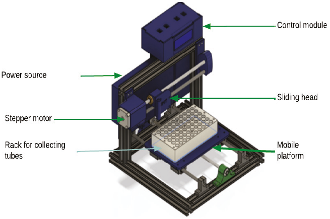
The design and simulation were carried out in FUSION 360 software, the complete design is shown in Figure 1 where the main components or modules can be identified. The positioning movement is in two axes, the base or mobile platform on which the rack with the collection tubes is placed, allows movement in the Y axis, while the sliding head that supports the hose moves in the X direction of the Cartesian plane of the collector.
The design of this device is based on the User-Centered Design methodology which implies 4 stages: Understand context of use, specify user requirements, propose design solutions, and evaluate against requirements. This methodology was selected because the project involves a very specific need in a specific environment: a fully functional device that offers similar results that a commercial device but with academic purposes.
Transmission system
The collector moves in two independent axes (X,Y), each movement is defined as a degree of freedom and each one requires a positioning system that has the task of moving the axes to the different positions. For this, it was decided to use ACME 8 mm TR8x2 4-start trapezoidal spindle screws that combine pitch precision, rigidity and delivery of torque with advance, made of 304 stainless steel (ASME SA213 Grade 304), due to its extensive use in systems such as 3D printers and CNC machines, its lower price compared to other similar systems and its resistance to wear. The selection of the screw covers important aspects that must be taken into consideration, such as the permissible axial load, the length and the way in which the ends are supported.
The lead screws work together with a pair of 8 mm rectified linear guides, made of AISI 304 stainless steel with a hard chrome surface finish, which have the task of minimizing friction, as well as the force required to move the mobile base and hose support along the axes using linear bearings to provide smooth and precise movement.
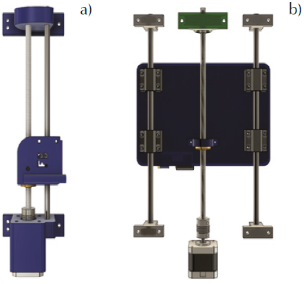
The supports of each one of the axes were also designed using the FUSION 360 software and manufactured by means of 3D printing (Figure 2a). As a support for the rectified bars in the Y axis (Figure 2b), supports for 8 mm aluminum axis model SK8 were used.
Diameter of linear guides of the Y motion system
To determine the diameter of the shafts, a length of 280 mm (length of the structure designed with the aluminum profiles) and a total mass of approximately 6 kg are considered, which includes the linear bearings, the bed, the base for tubes, the total tubes filled, plus a margin above the actual value of the total mass. With this, the total force and the punctual force at the supports are calculated.
Where g is the acceleration of gravity and m is the total mass. The total weight is distributed on two support rods, and each rod is supported by 2 linear bearings (W1 and W2) in the base or commutator bed and are separated by 85 mm from their centers on the rod as shown in Figure 3.
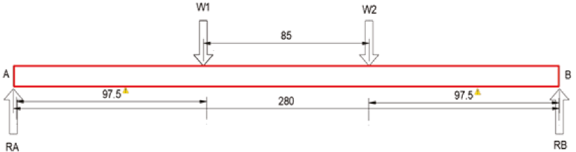
Summing forces and moments, the reaction RA y RB are calculated, in this case RA=14.7 N and RB=14.7 N.
Figure 4 shows the bending moment diagram, a graphic representation of the alteration in magnitude along the Y axis, which is subjected to a set of determined loads and with defined support conditions. The weight distribution is carried out on the 4 linear bearings that are separated by 85 mm from their centers as also shown in Figure 3.
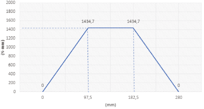
According to the Bending Moment Diagram shown in Figure 4, a maximum bending moment of 1.435 N-mm will be exerted in the beam. This diagram was obtained by carrying out a static bending moment analysis at each segment of the beam. According to the ED-Goodman criterion (Budynas & Nisbett, 2008), a minimum diameter of 6.8 mm should be selected. Finally, a commercial diameter of 8 mm is selected.
Diameter of linear guides of the X motion system
To determine the diameter of the X axis, the same procedure is carried out as for the case of the Y axis, considering a length of the axis of 280 mm and an estimated total mass of 920 g. Thus, the total force will be:
In the case of the X axis, the force will be distributed over a single linear bearing, as shown in Figure 5, therefore, the applied force W is 9.016 N.
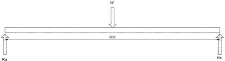
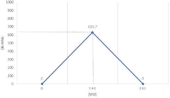
From the sum of forces and moments, the reactions Ra and Rb are calculated, resulting in Ra=Rb=4.51 N. With these results, the bending moment diagram (Figure 6) is drawn to determine the maximum bending moment and its location, and then calculate the minimum diameter of the rod on this axis. For this case the maximum bending moment is 631.7 N-mm.
Considering that the axes are not subjected to torsion,
Dimensioning of the motor´s torque
The choice of a motor is made based on the requirements of the application, for this project a stepper motor was chosen, since these motors allow precise positioning with ease. They are used in various types of equipment for precise control of rotation angle and speed using pulse signals. They generate high torque with a compact body and are ideal for quick acceleration and response.
One of the main parameters for the selection of a motor is the required torque or force. In this application, a motor is used to move the bed or base where the rack for the collection vessels will be mounted. To determine the necessary torque, the total mass and the friction coefficients must be taken into consideration.
For the Y axis, with a total mass of 6 kg, the coefficient of friction of the
linear bearings
Thus, the force exerted by the car (
y
Then the force necessary to move the car with the endless screw system is determined:
Finally, it is established that the force required to perform movement in the Y axis is:
Given the minimum force required for the movement of the base along the Y axis, the torque required by the motor is established, considering the movement relationship of the spindle in Equation (1).
Where:
T = minimum torque that the motor must deliver
F = minimum force required
r = work radius of the spindle
In which, D is the working diameter of the screw and p is the pitch of the screw, therefore:
Substituting in Equation (1) we obtain:
The dimensioning of the motor for the X axis is carried out in a similar way to
the dimensioning for the Y axis. An estimated total mass of 920 gr is
considered, the coefficient of friction of the linear bearings
y
Also, the force needed to move the carriage with the worm gear system
Finally, the force required to perform movement in the X axis is given by:
The torque required by the motor of X axis is established, taking into
consideration the spindle movement ratio
Also considering its size and price, a Nema 17 stepper motor is chosen. The torque required to generate movement on both axes is well below the capacity of any of the Nema 17 models, which guarantees correct operation in the system.
Stress and strain analysis
The analysis of the structure´s design was carried out using the Fusion 360 software, which allows simulations of stresses and strains by finite element analysis. The simulation yields a group of results, of which one of the most interesting are the Von mises stress, the safety factor, and the maximum displacement (deformation).
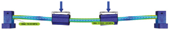
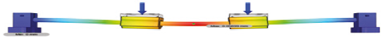
The Von Mises stress is a physical quantity proportional to the distortion of elastic strain energy that can be expressed as a function of the stress components. Figure 7 shows the result of the Von Mises stress analysis applying two loads of 14.715 N on the linear sliders. From this analysis, the result of combined stresses is obtained and compared with the yield stress of the material, it is found that the maximum is 18.03 MPa and the minimum is 7.495E-04 MPa. The analysis also shows that the largest stresses occur at the ends of the linear guide.
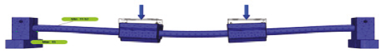
The safety factor is defined as the quotient between the calculated value of the maximum capacity of a system and the value of the actual expected requirement to which it will be subjected. For this reason, it must be a number greater than one, which indicates the excess capacity that the system has over its requirements. Figure 8 shows the value of the safety factor obtained from simulation results, two values are obtained, a minimum safety factor of 11.92 and a maximum of 15.
Deformation is the change in size or shape of a body due to external stresses produced by one or more forces. Figure 9 shows the simulation on the Y axis, it can be seen what the maximum displacement will be due to the applied loads, in this case it is a displacement of 0.05699 mm. Since it is a minimum displacement, it can be considered that there will be no deformations and the system will not suffer from structural failures. In addition, the maximum deformation, if it occurs, does not affect the accuracy or operation of the equipment.
It is important to mention that this analysis do not consider the plastic base of the axis created by 3D printing using PLA, because the behavior of this parts is hard to characterize in the simulation environment due to the 3D printing process variability such as layer orientation, temperature, humidity, infill percentage, among others. Also, the software used to simulate the deformation of this components do not take into consideration these variables, thus, results may not represent real behavior.
Electronic system
The control system for the fraction collector is implemented in the Arduino Uno development board (web: https://www.arduino.cc/), this is responsible for controlling the motors by moving the actuators on the X and Y axes. The system incorporates a simple user interface consisting of an LCD screen and a set of buttons that allow the user to set operating parameters.
Figure 10 shows the electronic diagram of the fraction collector, being the Arduino uno board the central component. The stepper motors are controlled through the A4988 driver connected to pins 3, 4, 5 and 6 of the Arduino, one pair for each controller; this pair of pins indicates the number of steps and the direction of the motor rotation. The figure also shows the connection of the four collector user interface buttons connected to pins 7, 8, 9 and 10.
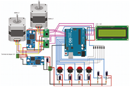
The circuit includes two voltage regulators, one for the 5V power supply of the controllers and the other to power the 5V of the buttons and two limit switches that serve to indicate the initial positions of the equipment.
An LCD to I2C interface adapter module is used for the connection of the LCD screen with the Arduino Uno, it allows to easily handle the LCD with only two pins (SDA and SCL), connected in this case to A4 and A5 of the Arduino.
User interface
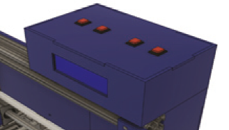
Figure 11 shows a view from Fusion360 of the user interface, on the LCD the user can see a menu of options, instructions and monitoring of the process, and the 4 buttons, labeled OK, BACK, DOWN and UP, allow user interaction.
Control module
The task of the fraction collector is to collect a determined number of fractions (samples) selected by the user. The collection of these is done at fixed time intervals also defined by the user. Based on these parameters, the Arduino controls the movement of the collector head (through the stepper motor) to position it on each collection microtube, for this, it must measure the elapsed time since it was positioned in the current sample. Time measurement in Arduino is done by handling internal timers or interrupts. For this the TimerOne library is used in this project, this library allows the use of timers in a simple way.
Collector operation
The collector asks the user for two parameters, the number of samples to be collected and the time that must elapse before changing the head to the next one to collect the next sample.
To start, with the fraction collector's AC 110V power cord connected, the On/Off switch is turned on. The screen shows a welcome message for a few seconds and then a phrase appears requesting the number of samples and instantly sends a message to press the OK button. Once the parameters are selected a message will appear to start, press OK to start or BACK to return to the selection of samples. Pressing OK displays the message "Starting", and the motors are placed in their initial positions to start collecting the samples. Before starting the collection, an open valve message is displayed on the screen, this is a defined time that is given to the user to open the valve that allows the passage of fluid. During the process, the current sample number will be displayed on the screen, and at the end of the process an automatic restart is made, a message to press OK is displayed on the screen and the procedure is repeated.
Results
The validation of the correct operation of the equipment was carried out in two stages, the first verifying the operation of the control system through timing tests and later tests of the operation of the complete equipment.
Timing test of Arduino Uno
As mentioned in the previous section, the Arduino controls the movement of the collector head (through the stepper motor) to position it in each collection microtube according to the parameters established by the user.
The Arduino must then measure the time elapsed since it was positioned on the current sample and check before changing the head to the next one it had to collect the next sample. Timing tests were performed for a fixed value of 1 second, showing the time count in seconds on the serial monitor. Through an interpolation of the obtained data, it was possible to estimate that the efficiency of the timer is 97 % with a margin of error of ± 3%. This indicates that the collector must fulfill the function of collecting samples at defined times without losing large amounts of volume during sampling.
Fraction collector function test
The test carried out consisted of taking 10 samples at a set time of 1 m for each one, a peristaltic pump was used to pump water to a column for chromatography at a defined flow of 500 µl per minute, and the fraction collector was used to collecting the samples as shown in Figure 12.
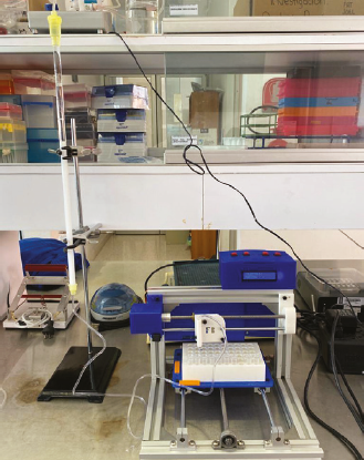
Once the test was finished, an analytical balance was used to measure the weight in each tube with the collected samples. The conical tubes used have an approximate weight of 1 gram, and with the defined flow of 500 µl per minute, this means a container's weight of approximately 1.5 grams (in relation to the density of water which is 1 kg/ L). The results are shown in Table 2, an average weight of 1.6798 grams and a standard deviation of 0.0234 grams were obtained, for the application this difference is considered non-significant, which validates the correct operation of the developed equipment.
Conclusions
The fraction collector is essential laboratory equipment to make mixture separation techniques more efficient. Its high cost makes it necessary to design and develop accessible and easy-to-use equipment, especially for educational institutions or research centers that have limited resources. This work presents the design, construction, and validation of a fraction collector for liquid chromatography.
A chromatographic system consists of several modules and control and recording systems that work in an integrated or modular way. In this project, a modular fraction collector was developed which has independence from control systems such as flow, pressure, detection, etc.; it has been designed to provide versatility in handling, and to be able to be coupled to different chromatographic systems.
The structural design is based on a Cartesian-type system and through 3D printing (currently booming technology) different components that make up the collector were developed, this technology facilitates construction and allows the use of accessible and economical materials (Jorquera, 2016, Varela, 2020). For its operation, the collector takes as input variables the number of samples and the time between each one.
Caputo et al. (2019) developed a fraction collector using LEGO MINDSTORMS pieces, which presents a basic and simple operation, and is presented as a low-cost system. However, the system costs could be reduced by employing an Arduino platform, and incorporating parts created by 3D printing.
The Arduino development platform has demonstrated its versatility and capacity in countless projects and applications, some examples are found in the works of Badamasi (2014), Alhamad et al. (2021), Robila et al. (2021) and Odongo et al. (2022). In this project, the Arduino Uno performance has been adequate, it controls the operation and the user interface of the designed equipment.
The validation of the structural design was carried out through a study of stresses and deformations, as well as a finite element analysis to rule out any possible failure. Arduino timing tests were also carried out, and finally tests of the complete equipment. It has a fraction collector, robust, integrated, and easy to use.
Undoubtedly, the developed device meets the basic needs of collecting fractions generated in a chromatographic run, however, there are points for improvement that help optimize and diversify its functions. Among the improvements that can be made, we identify the following: Redesign the user interface, add IoT functionality to be able to monitor processes remotely (maintaining its versatility and independence), as well as improving the quality of some components, for example, some bearings and parts made by 3D printing.
Additionally, the functionality of this equipment can be increased by allowing the use of different containers for the collected fractions, for which it is necessary to adapt racks that meet these needs, as well as the regulation of the flow of the mobile phase, pressure control and subsequent blockage of the system. Regarding the design of the structure, the control module and the user interface could be relocated to improve the aesthetics and functionality of the collector.
Finally, we can conclude that equipment designed and manufactured using 3D printing techniques and development boards such as Arduino can be used in real applications that require precision movements, thus reducing manufacturing and development costs.

