


 nueva página del texto (beta)
 Inglés (pdf)
 Artículo en XML
 Referencias del artículo
 Enviar artículo por email
 Citado por SciELO
  Similares en
SciELO
Similares en
SciELO 
 Permalink
Introduction
The occurrence of sinkholes such as the one in Santa Maria Zacatepec Puebla, Mexico, or the sinkhole in the parking lot of Bombay in India, makes us think about the frequency at which this phenomenon occurs, thus the question arises: how often does this phenomenon occur?
According to Britannica (2021), a sinkhole is a circular depression also called doline, it is formed when subway water disintegrates the vault of a cavern located in a soil or limestone rock. The doline is the most common structure in karst areas. Sinkholes vary in size and depth, and two main types can be identified:
Those caused by the collapse of a cavern vault.
Those caused by the gradual dissolution of the existing rock beneath a soil stratum.
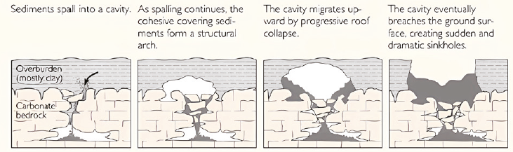
Sinkholes generally present conditions that allow the flow of water into the subsoil, because the infiltration zones of the sinkholes are superficial and sometimes these are obstructed by clay plugs, thus forming a body of water, and it is not until the cementing agents of the soil are dispersed with the water that the conduit appears at the bottom of the sinkhole (Britannica, 2021) (Figure 1).

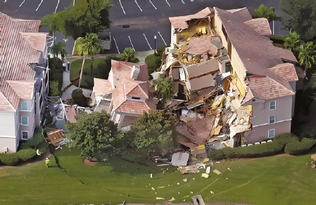
In arid and semi-arid areas of our planet, it is common to find soils with complex behavior often damaging buildings as a result of the differential movements they cause Ayadat & Hanna; (2011) and Abbaslou et al. (2020) and the reason why they are called difficult soils, this is the case of expansive soils, collapsible soils, and landfills (Das, 1999). In collapsible soils, also called metastable soils, it is common to see the sudden appearance of sinkholes (dolines) during the rainy season, as a consequence of the destruction of the soil structure when its particles migrate and consequently form conduits and large subway cavities called caverns, caused by the subway flow (Figure 2). Caverns may collapse when the subway weathering process becomes more severe, and due to their size and unstable conditions, thus causing the sudden appearance of a sinkhole, as mentioned by Knodel (1991), and Das (1999) and Abbaslou et al. (2016) as shown in Figure 3.
Ayadat & Hanna (2011) stated that a combination of factors interacts in metastable soils such as the type of soil, its mineralogy, grain size distribution, applied stress levels, degree of saturation, its specific weight, the nature of the cementing agent, the chemical nature of the pore water, wetting and drying cycles, rainwater infiltration processes; these are an accumulation of variables that generate the large sudden subsidence in the ground without an apparent explanation, this phenomenon is known as “sinkhole”.
Due to the recent appearance of cavities and landslides in the vicinity of new housing estates, engineers must take the necessary precautions to avoid the loss of human lives, damage to homes, and infrastructure detriment, having stated, accurate identification of the type of soil, and correct assessment of collapse risk, erosion and/or generation of voids become fundamental and a high priority step (Ayadat & Hanna, 2011).
In nature there are fine soils called loess, which are quaternary aeolian soil deposits (wind soil) Reginatto (1977) and Abbaslou et al. (2016), where it is possible to locate particles bound by carbonates and capillary water. The structure adopted by this type of soil is open with diameters ranging between 20 and 60 μm, causing this structure to collapse in the presence of water or the action of imposed loads (Jefferson et al. 2000; González & Armas, 2008). Within loessial soils, also called erodible soils, two peculiar behaviors can be differentiated:
Dispersive soils: the presence of fines is significant, and, in some cases, they contain percentages of clay with dissolved salt contents of 40 % up to 60 % (González & Armas, 2008 and Carey, 2014).
Erodible soils: contain appreciable content of fine sands, rock dust, and alluvial deposits whose peculiarity is that they present a very uniform size distribution, high void ratios, specific weights, and reduced cohesion.
Das (1999) mentions that in many regions of the world, certain soils hinder the development of new buildings, and the behavior of the foundations of existing buildings is complex because they can cause differential movements or sudden movements. Unsaturated soils present high resistance and low deformations at low water content; however, when these soils are overhydrated, their resistance to shear stress is reduced, and their deformation increases. On the other hand, Redolfi (2007) points out that there are soils that experience the behavior described above and that are not recommended for fills or embankments, even when they are partially saturated, they can receive high stresses, however, when fully saturated they lose their structure and therefore experience sudden changes in their volume.
In addition, González & Armas (2008), point out that it has been proven that clay soils can be highly erodible because some natural clays disperse or deflocculate in the presence of pure water. Dispersive soils, located in places where water flow may occur, are highly susceptible to erosion or sufussion. This behavior depends on the mineralogy of the soil particles, the salts dissolved in the pore water, and the type of water that comes into contact with them (González & Armas, 2008; Abbaslou et al. 2016). As mentioned by Abbaslou et al. (2020), the repulsive forces between clay particles increase due to the concentration of sodium ions in the pore water, which causes the dispersion of the particles. As a result, these soils erode rapidly through the flow of water, migrating as individual particles without binding to each other.
This erosion process can begin when water infiltrates into the soil through drying cracks, cracks due to settlement, cracks in the walls of channels, leaks in water lines or drains in poor condition, leaks in cisterns, rising water tables, or surface runoff. González & Armas (2008), Abbaslou et al. 2016 and Abbaslou et al. 2020 found that the susceptibility of dispersive clays is due to the nature of the cations present in their pore water. Thus, dispersive soils contain a high concentration of sodium cations in the pore water, they can also present calcium, magnesium, and potassium cations, in contrast to ordinary soils that only contain in their pore water a higher concentration of calcium, potassium, and magnesium cations, see Sayehvand & Dehghani (2014) and DJOROVIC et al (2018).
Knodel (1991) highlights that this type of soil shows a specific geological origin, frequently located in the water currents that run on the inclined surfaces of the soil, in lake deposits, loess deposits, and plains deposits (Martinez, 2018). In these places, lumps, granite, sandstone, and shales, as well as marine deposits, present the same salts in the pore water, which makes them dispersive (Ksenija et al., 2018). On the other hand, Knodel (1991) states that dispersive soils are located in areas with arid and semi-arid climates in which alkaline soils are located. In addition, the matrix of these soils contains clay unions and some leachates from rainwater, which allows them to exhibit high resistance when they are unsaturated (Jennings & Knight, 1975), however, when their moisture increases, their resistance is drastically reduced. In addition, suffusion can occur in any clayey soil if the water infiltration velocity ranges from 91.44 to 121.92 cm/sec (3 to 4 ft/sec) (McCarthy, 1982). The dispersive behavior of these soils has been demonstrated in many hydraulic projects in which this type of soil has been in contact with water.
In Los Angeles, Rioverde, SLP, after a heavy rain, a hollow suddenly appeared at a two-street intersection, so the inhabitants of this place asked the government agencies to investigate the nature of this cavity. Once they ruled out different possibilities such as this hole being a water extraction well, that it was the void left by a large root that disintegrated over time, it is a tunnel, or that it was the burrow of some large animal, it was stated that this place was located in an arid to semi-arid climate zone, where soils of eolian origin outcrop and in which underlie rock strata of sedimentary origin. This was enough evidence to suggest that the cavity in question could be the conduit of a doline, which could be connected with a subway cavern and, if the proper conditions were met, the formation of a sinkhole was probable.
Based on the previous statements, the objective of this work was to rule out the sudden appearance of a sinkhole in the town of Los Angeles, belonging to the municipality of Rioverde, SLP, to avoid any risks to the population, damage to the heritage of families and infrastructure of the city.
Methodology
To study the sinkhole in the town of Los Angeles where a cavity appeared, and evaluate the possibility of suffusion or the presence of caverns, and their collapse at the intersection of Juan de la Barrera St. and Miguel Hidalgo St., the investigation was carried out in 6 stages, as described below:
Stage 1. Place a visit to the town of Los Angeles to gather information and neighbors’ impressions about the situation.
Stage 2. Verify the topography of the site and locate bodies of water or other sources of wetting.
Stage 3. Explore the area using a handheld Penetrometer and recover an integral sample of the site.
Stage 4. Perform conventional geotechnical tests to characterize the soils, determine their moisture profile, and evaluate the possibility of dispersion, suffusion, or collapse.
Stage 5. Model the distribution of stresses in the subsoil.
Stage 6. Discussion of the results.
Results
Stage 1: Location
The location of the hollow is shown in Figure 4.
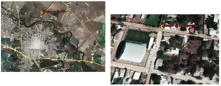
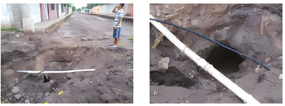
At the intersection of Miguel Hidalgo St. and Juan de la Barrera St., in the town of Los Angeles, the cavity shown in Figure 5 was identified. Upon inspecting the cavity it was found that it is not regular; on the surface, it had a diameter of approximately 0.80 m, with a visible diameter at the bottom of approximately 2.00 m and 2.80 m in depth.
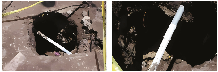
The bottom of the cavity showed a series of branches mostly directed towards the northeast.
Stage 2: The topography of the site was determined and wetting sources and bodies of water were located
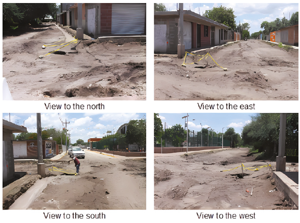
Surface runoff occurs in the North to South and East to West direction, it accumulates at the intersection of the streets as it is the lowest part and it is the place where water infiltration into the subsoil occurs (Figure 6). In addition, the municipal water pipe is located in the upper part of the cavity and the municipal sewage system manhole is located 3.00 m away.
Exploration
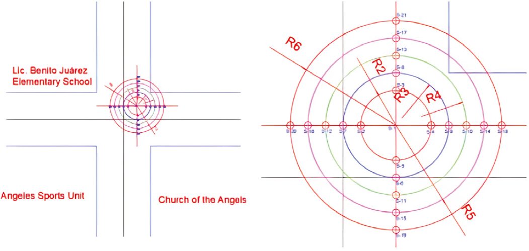
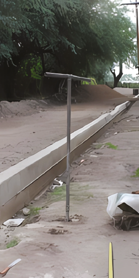
To characterize the subsoil of the site, a probing campaign was carried out using the Handheld Dynamic Penetrometer (Figure 7).
The results obtained are shown in Figures 8, 9, 10, and 11.
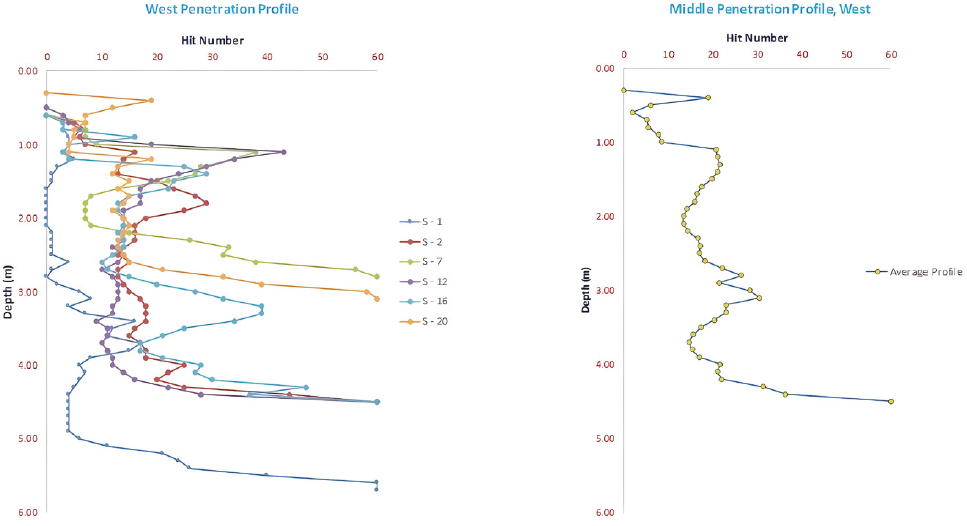
The behavior of penetration resistance (PR) of the probes of the west end-labeled S-1, S-2, S-7, S-12, S-16, and S-20 are shown in Figure 8; in probe S-1 it was possible to observe that the resistance of the soil is very low up to a depth of 5.10 m, likewise probes S-2, S-7, S-12, S-16 and S-20, located to the west of the cavity, show that the soil presents low resistance to penetration from the surface to a depth of 1.00 m and that the soil is competent starting at a depth of 4.50 m.
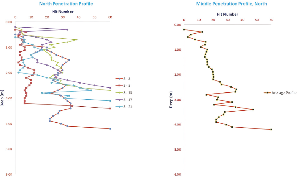
On the other hand, probes S-3, S-8, S-13, S-17, and S-21 (Figure 9), located on the north side, show that the PR is low from the surface up to a depth of 0.70 m, in S-8 it can be seen that the PR is low up to a depth of 3.20 m. In contrast, it was observed that the soil is competent starting at a depth of 4.20 m.
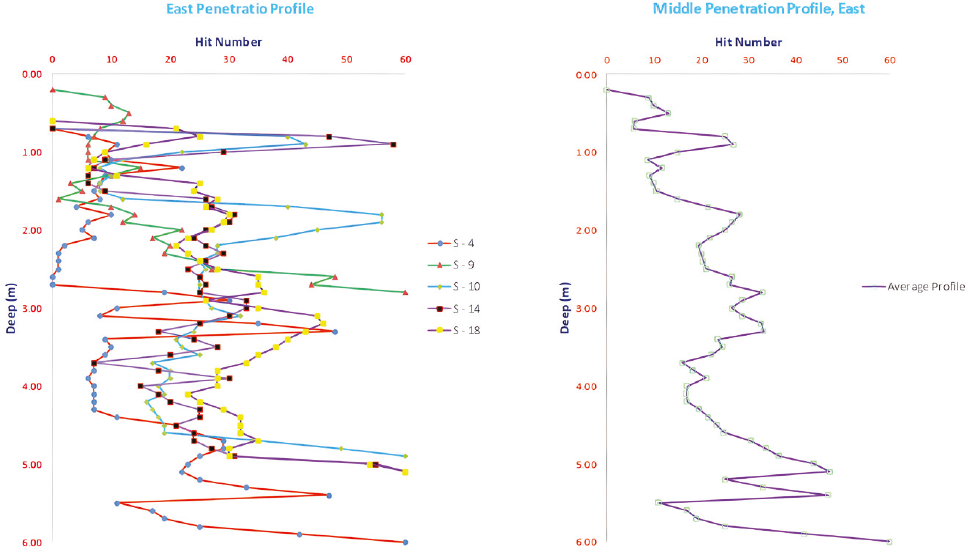
Figure 10 shows the east end, in probes S-4, S-9, S-10, S-14, and S-18, it is appreciated that the soil has low RP from the surface to 1.50 m in depth, particularly, S-4 has low RP and the soil is competent starting at 6.00 m deep.
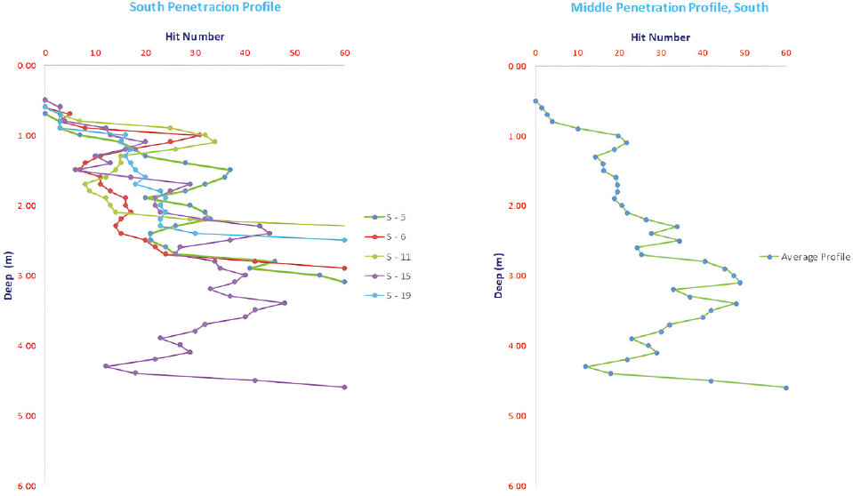
Figure 11 presents the exploration of the south end with probes S-5, S-6, S-11, S-15, and S-19, here it can be observed that the soil presents low RP from the surface up to a depth of 0.90 m, and the soil is competent at 4.60 m deep.
Case Study: Al-Jubail, Kingdom of Saudi Arabia by (Abdulrahman et al., 2015)
There are numerous cases of application of the Manual Dynamic Penetrometer (DCP) reported in the literature, the objective of these works was to explore the subsoil to know its homogeneity, identify the presence of the water table, the location of discontinuities prior to the choice of the foundation Depth and the most recommended and economical type of foundation (Silva & Terán, 2015).
According to Silva & Terán (2015), one of the benefits of this technique is that it provides a continuous record, with reliable depths of 8.0 to 10.0 m, which can allow it to be related to the materials that underlie the place, the presence of voids and the location of the water table. This information will allow the generation of a three-dimensional model of the site under study, to model the distribution of stresses in the soil mass, and to know the deformations that may occur. On the other hand, there are several empirical correlations of the Manual Dynamic Penetrometer which allow us to know the Simple Compressive Strength of the soil at different depths, the homogeneity of the soil strata, the Load Capacity, etc. Furthermore, in the case of communication routes, it is possible to infer the CBR, Compaction, Density, the location of the best Subgrade to accommodate the roads, and the development of increasingly hasty foundations.
On the other hand, the PDC test is affected by the fines present, the moisture content, the granulometry and the vertical pressure acting on the column of the penetrometer bars (Deepika & Chakravarthi, 2012). Now it presents a comparison of the results obtained in this work, with those presented by (Abdulrahman et al., 2015), during the verification of soil densification and its homogeneity, of a property industrial of Saudi Arabia, obtained by means of the nuclear densimeter and the resistance to penetration obtained by means of the Manual Dynamic Penetrometer, respectively. These results were compared with the results of the S-2, S-3, S-4, and S-5 probes, developed in the community of Los Angeles, where it was possible to corroborate that the results of the Manual Dynamic Penetrometer were useful in the exploration of the subsoil and the identification of its homogeneity, as it was necessary to determine it, in the case study of the void formed at the intersection of the aforementioned streets (Figure 12).
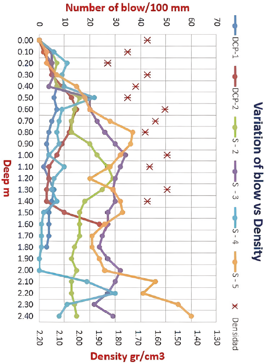
Figure 12: Comparison between the results obtained by (Abdulrahman et al., 2015) and those obtained in Los Angeles
From this exploration (Figure 13) it was possible to conclude that:
A hollow with an upper diameter of 0.80 m, a lower diameter of approximately 2.00 m, and a depth of 2.80 m is present.
There is an infiltration point at the intersection of the streets, where the cavity is located.
The depth of the NAF in the water extraction wells is 12 meters.
The soil in the center of the sinkhole presents low RP from the surface up to 4.80 m deep.
Empty conduits were identified in the subsoil in the northeast direction.
The Manual Dynamic Penetrometer is a useful tool to verify the homogeneity and presence of voids in the subsoil.
Sampling methodology
To characterize the soil at the site of interest, sampling was done using a posting shovel, from the soil surface up to a depth of 4.80 m, as shown in Figure 14. The soil samples were transported to and tested in the laboratory.
Stage 4. Laboratory tests
a) Soil characterization according to the Unified Soil Classification System.
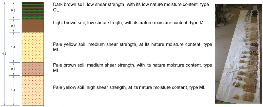
Based on the ASTM C136-01, ASTM D4318-05, and ASTM D2487-83 standards, the existing soil profile was obtained from the samples taken at the site of interest (Figure 15).
Once the samples were tested, the soil was classified according to the Unified Soil Classification System ASTM D2487-83 (Table 1).
Table 1: Property of the soil sample
| EW Layer | Layer | Thickgness | Depht | w | Gravel | Sand | Fine | Silt | Clay | wL. L. | w P. L. | w P. I. | Ss | γm | γd | USCS |
|---|---|---|---|---|---|---|---|---|---|---|---|---|---|---|---|---|
| m | m | % | % | % | % | % | % | % | % | % | KN/m3 | KN/m3 | ||||
| 0.00 | ||||||||||||||||
| 1 | 1 | 0.8 | 0.80 | 20.047 | 0.71 | 29.55 | 69.74 | 43.33 | 22.70 | 20.62 | 15.90 | 12.85 | CL | |||
| 2 | 0.6 | 1.40 | 34.82 | 0.59 | 7.38 | 92.03 | 81.46 | 10.57 | 47.06 | 38.14 | 8.91 | 3.05 | 15.20 | 11.57 | ML | |
| 3 | 1.4 | 2.80 | 26.69 | 0.00 | 1.95 | 98.05 | 51.88 | 46.17 | 48.56 | N.P. | N.P. | 14.51 | 9.81 | ML | ||
| 4 | 0.6 | 3.40 | 32.54 | 0.06 | 3.29 | 96.65 | 88.65 | 8.00 | 42.21 | 31.83 | 10.38 | ML | ||||
| 5 | 1.4 | 4.80 | 36.76 | 0.03 | 2.73 | 97.23 | 93.23 | 4.00 | 43.34 | N.P. | N.P. | 15.00 | 11.08 | ML |
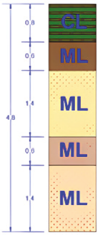
Using Table 1, it was possible to identify that the soil has a five strata profile; the first layer is formed by an inorganic clay of low plasticity, type CL, the second layer is inorganic silt of low compressibility, type ML, the third layer is inorganic silt of low compressibility, type ML, the fourth layer is inorganic silt of low compressibility, type ML, and the fifth layer is inorganic silt of low compressibility, type ML (Figure 16).
b) Characterization of the 2nd layer according to American Society for Testing and Materials D 5333-03.
To evaluate the likelihood of collapsing of this soil, the collapse index was determined according to the procedure stated by the ASTM-D-5333-03 (2003), the results are shown in Figure 17.
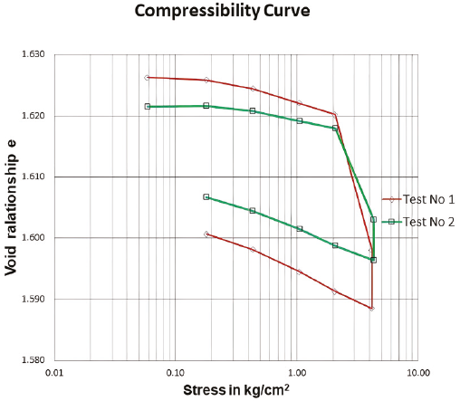
Based on Figure 17, and Table 2, it was determined that when the soil is at its natural moisture content, it can support up to 20 Ton/m2 without exhibiting excessive deformations; however, if this soil is subjected to hydration, a collapse index of 0.31 can be reached, this is consistent with a soil slightly propensity to collapse.
Table 2: Collapse index of the 2nd stratum soil
| Test | Collaps Index Ic | Soil collapse grade accordings to ASTMD 5333-03 |
|---|---|---|
| 1 | 0.37 | slightly |
| 2 | 0.26 | slightly |
| 0.31 | slightly |
c) Soil characterization of the 2nd, 3rd, 4th, and 5th strata, according to American Society for Testing and Materials D 4221-99.
To study the dispersive behavior of the soil, a double hydrometer grain size distribution analysis was performed, according to the ASTM 422-63 (2003), and the ASTM 4221-99 (1999), the results are shown in Figure 18.
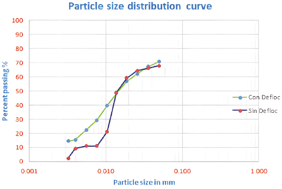
Based on the procedure established by the ASTM 422-63 (2003), it was determined that the soil presented the behavior shown in Table 3, see too Maharaj & Paige, (2013).
Table 3: Double hydrometer test results
| Layer | A Without Defloc |
B With Defloc |
Degree of dispersion |
Dispersion Identification |
|---|---|---|---|---|
| 2 | 10.94 | 20.00 | 54.70 | Intermediate |
| 3 | 9.43 | 46.17 | 20.42 | Non Dispersive |
| 4 | 11.11 | 45.51 | 24.41 | Non Dispersive |
| 5 | 8.00 | 33.00 | 24.24 | Non Dispersive |
With the information presented in Table 3, it was possible to say that only the 2nd stratum presents a dispersive behavior of intermediate degree.
d) Characterization of the 2nd stratum according to the American Society for Testing and Materials D 4647-93, by Pinhole test.
To identify the soils present, two Pinhole tests (Figure 19) were performed on the soil located in the 2nd stratum, since it is an alkaline soil, the results are presented in Table 4.
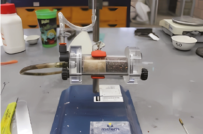
Table 4: Results of the Pinhole test on the 2nd stratum
| No | Hydraulic load in mm |
Test time with the given load in min |
Flow rate in ml/sec |
Flow turbidity | Hole diameter before test |
Hole diameter after test |
Dispersive classification |
|---|---|---|---|---|---|---|---|
| 1 | 50.80 | 3.00 | 0.33 | Clear | 1.11 | 1.54 | Non Dispersive |
| 2 | 177.80 | 8.00 | 0.77 | Clear | 1.11 | 1.54 | Non Dispersive |
| 3 | 381.00 | 13.00 | 1.18 | Clear | 1.11 | 1.54 | Non Dispersive |
Although the soil was classified as ND1 (non-dispersive) type, any fissure in the soil subjected to the water flow may experience erosion, so suffusion could appear inside the soil (Maharaj & Green, 2015).
Stage 5. Modeling the stress distribution behavior in the soil mass
To know the stress distribution of the underground in the area where the cavity appeared, an overload pressure of 60 kPa (6.12 Ton/m2) was applied to a two-floor low-income dwelling, as shown in Figure 20.
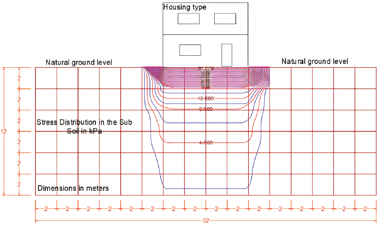
Figure 20: Stress distribution in the subsoil under loads of a platform supporting the structure of a 2-story house. The curves are the isobars obtained with the nodes or stress interpolation points
The distribution of stresses in the subsoil shown in Figure 20 represents the case of a soil platform 2.00 m high with a specific weight of 17.17 kN/m3, that supports the structure of a 2-storey house, with an applied pressure on the ground of the site of 94.34 kPa. It was observed that due to the theory of elasticity, the stresses applied on the surface dissipate at a depth of 3.50 m, that is, they are reduced to 10 %, and 8.50 m before the groundwater level is reached, therefore, the possibility that the caverns could collapse is not considered, due to the overload imposed, in case there were.
Stage 6. Discussion of the results
The slope on the surface of the terrain causes the accumulation of water at the intersection of the aforementioned streets, where the water line and the drainage line also meet, and, in addition, the static level of the water extraction wells is at a depth of 12 meters.
The soil profile showed five strata at the site of interest; the first stratum goes from the surface to 0.80 m underground and it is a CL-type soil (Low plasticity inorganic clay), the second stratum goes from 0.80 m to 1.40 m underground and it is an ML-type soil (Low compressibility inorganic silt), the third stratum goes from 1.40 m to 2.80 m underground and it is an ML-type soil (Low compressibility inorganic silt), the fourth stratum goes from 2.80 m to 3.40 m underground and it is an ML-type soil (Low compressibility inorganic silt), and the fifth stratum goes from 3.40 m to 4.80 m and is an ML-type soil (low compressibility inorganic silt).
The soils located in the 2nd, 3rd, 4th, and 5th strata have an appreciable content of clayey fines, and by applying the Double Hydrometer test it was possible to discover that the soil of the 2nd stratum is susceptible to dispersion, to an intermediate degree.
In addition, the pinhole test helped determine that the soil of the 2nd layer is not susceptible to dispersion, however, it is susceptible to erosion.
Particularly, the 2nd layer of soil shows significant resistance and little deformation when naturally moisturized; however, when hydrated, it may experience a slight propensity to collapse.
A truncated conical cavity was located with 0.80 m in diameter on the surface, 2.00 m in diameter at the bottom, and 2.80 m in depth. Inside it showed several ducts of up to 40 cm in diameter, partially obstructed with residues of the collapsed vault; in addition, the soil adjacent to the cavity showed low resistance due to saturation. It was also possible to identify the presence of subway conduits branching in different directions. The main conduit is directed towards the northeast. All of the above confirms the hypothesis that we are in the presence of a sinkhole.
Recommendations
In cases where there is the possibility of the presence of sinkholes in urbanized areas with conditions similar to those described in this work, and making the necessary adjustments, it is recommended to carry out basic actions such as:
Check the drinking water and sewage lines.
Locate the presence of wells, cisterns, or flushes.
Perform a geo-hydrological study of the site.
Explore the subsurface of the area, using geophysical equipment, to locate conduits or voids.
Prevent the accumulation of surface and groundwater.
Clean out the sinkhole.
Seal the conduits using fluid concrete.
Seal the main cavity with cyclopean concrete.
Backfill the sinkhole by layer-placing gypsum-stabilized soil with a moisture content close to its optimum and strong compaction.
Place a geomembrane close to the surface to prevent water from infiltrating into the soil.
The confirmation of these works may reduce the execution of additional investigations.
Conclusions reached
The unevenness of the street causes the accumulation of water.
Rainwater accumulated on the surface and in the subsoil, there was a leak in the drinking water line.
In the type of soil found, it is common for collapse to occur.
The tests carried out showed that the soil is susceptible to erosion and collapse.
The resistance of the analyzed soil is reduced with humidity.
At the site, a frustoconical cavity with branched underground ducts appeared.
Given the conditions mentioned, it is possible to repair the hole that appeared at the intersection of the streets.

