


 nueva página del texto (beta)
 Inglés (pdf)
 Artículo en XML
 Referencias del artículo
 Enviar artículo por email
 Citado por SciELO
  Similares en
SciELO
Similares en
SciELO 
 Permalink
INTRODUCTION
Sometimes, different diseases or physical or chemical aggressions can lead to a loss or alteration of the cells of a tissue or organ. The normal restitution of this tissue is the main purpose of regenerative medicine [1]. Tissue engineering is a new area of regenerative medicine whose objective is the construction of in vitro tissues for a therapeutic use, that allows to restoring, replacing, or increasing the functional activities of the organic tissues themselves [2]. Basically, tissue engineering consists of growing cells in an enriched three-dimensional matrix, where these cells can grow and later be transplanted into a recipient organ [3]. Three components can be distinguished: cells, biomaterials (the extracellular matrix or supporting scaffolds) and growth factors. This paper will focus specifically on contributing information and methodologies in the construction of scaffolds for cartilaginous tissue. Among its possible applications is the aesthetic treatment of microtia, a congenital malformation of the external ear that ranges from mild structural anomalies to the complete absence of the ear, with a prevalence rate that varies significantly between countries ranging from 0.8 to 17.4 per 10,000 births, with a higher prevalence reported in Ecuadorians, Chileans and Finns, with prevalence of 17.4; 8.8 and 4.3 respectively for every 10,000 births [4]. Current cosmetic treatment options for children include reconstruction with prosthesis, combination of prosthesis and own tissue, and autologous rib cartilage transplant.
Scaffolds, which can be manufactured by 3D printing, are highly porous three-dimensional substrates that house cells, providing a surface to which they can adhere, thrive and multiply [5]; consequently, they generate an extracellular matrix (ECM) of structural and functional proteins and saccharides that form living tissue [6]. This type of structure has been used in different organs such as bone tissues or soft tissues [7]. During the last decades, much research has been carried out regarding structural capacity [8], biocompatibility, cell growth speed [9], shape and manufacturing process [10], among others. These investigations have generated extensive and interesting information that has made it possible to make considerable improvements in this discipline. More recently, diverse medical sub-specialties have started considering novel 3D bioprinting approaches, based on the concept of combining living cells and biomaterials, controlling cell proliferation, attachment, and migration within 3D printed scaffolds [11]. Currently, it is possible to design and manufacture cartilage in the shape of an ear, in vitro, which is subsequently implanted under the patient's skin. However, we must consider that these are new procedures and there is still a need to improve the methodologies and materials used. For this reason, it is important to define and evaluate manufacturing parameters to guarantee the manufacture quality of scaffolds. Different parameters such as material, geometry and pore size are evaluated, indicating how the manufacturing process can alter the expected result.
Two biocompatible and biodegradable materials, polycaprolactone (PCL) and polylactic acid (PLA), were used to manufacture the scaffolds. While there are other biocompatible materials, these two materials were used primarily because they are economic, although both present different difficulties in their manufacture. These materials will generate printing parameters that can be extrapolated to other biocompatible materials with similar characteristics.
MATERIALS AND METHODS
The steps needed to allow the characterization of the necessary parameters for 3D scaffolding printing will be developed in the following section.
Experiment design
Based on the information collected from studies of the geometry importance for cell growth, the size of the manufactured pores ranged between 200 µm and 600 µm [12] [13]. As for the shape, square, triangular and ellipsoidal geometries were defined. The repetitiveness of the experiment was set to 6 times for each combination. This is because the printers are manually calibrated, which interferes with the equality between one scaffold and another. Coupled with this inaccuracy, it was considered the diameter variation in the of the PLA material, it is +/- 0.05 mm which also influences the accuracy of pore size.
Design and computational modeling of scaffolding
For the design of the PLA and PCL scaffolds, it is essential to define the following geometric parameters: l (scaffold length), p (pore size), h (scaffold height) and e (filament thickness). These parameters can be seen in Figure 1.
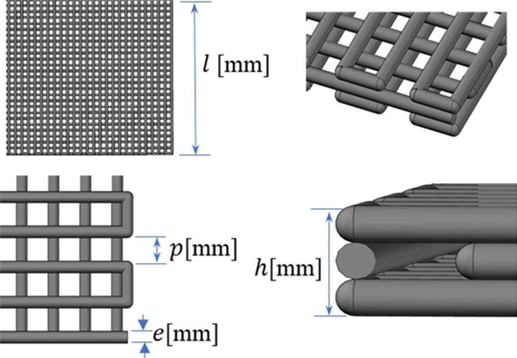
Figure 1 Top, three-dimensional view and dimensions (parameters) of the square scaffold. Source: self-made.
Once these parameters were defined, it was necessary to define the type of pore geometry. In this work, the geometries shown in Tables 1 and 2 were evaluated. Table 1 considers the geometries manufactured with PLA and Table 2 considers the geometries manufactured with PLC.
Table 1 PLA scaffolding dimensions.
| Square | Triangular | Ellipsoidal |
|---|---|---|
|
|
 |
|
p1= 600 µm - b3: 300 µm p1= 450 µm - b2: 225 µm p1= 300 µm |
ᶩ = 20 mm e = 200 µm h = 1,2 mm |
|
Table 2 PCL scaffolding dimensions.
| Square | |
|---|---|

| |
|
p1= 200 µm p1= 400 µm p1= 400 µm |
ᶩ = 20 mm e = 400 µm h = 1,2 mm |
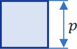
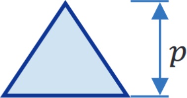
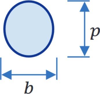
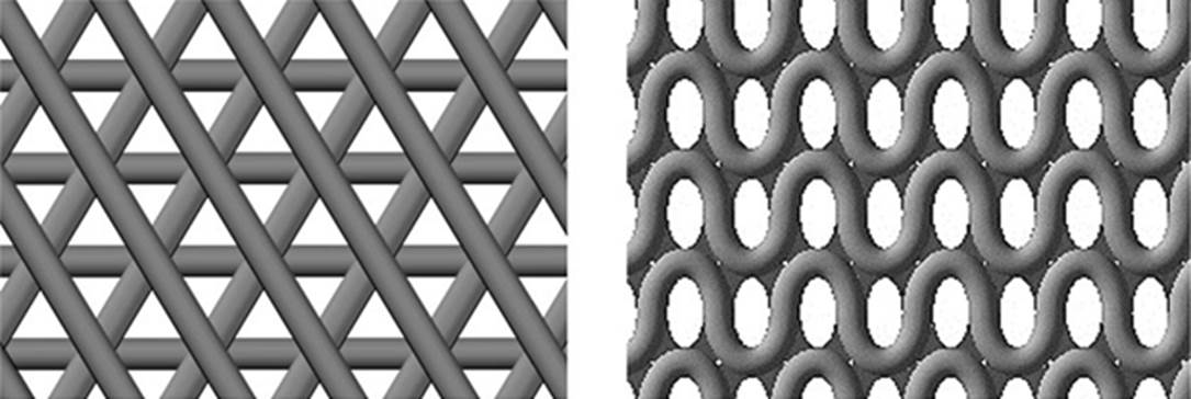
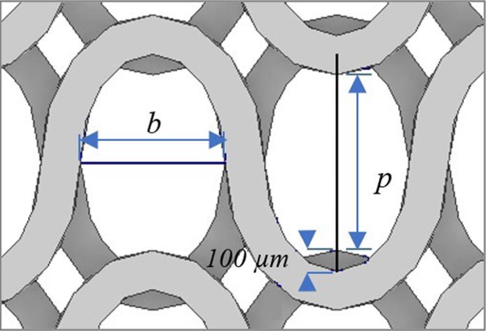
The pore size is represented by p and b parameter. For square and triangular geometries three scaffolds were defined, for ellipsoidal geometry just two scaffolds were defined. Figure 2 shows the structure of triangular and ellipsoidal scaffolding.
3D Print
This section shows the commercial properties of the materials to be printed, the machine considered for 3D printing in both PLA and PCL, in addition to the printing protocol.
Materials
Table 3 shows the characteristics of the materials used for the manufacture of scaffolding. The PLA filament, despite not having a biocompatibility certificate, was chosen because it is based on natural resins, without additives or colorants. It should be noted that the PLC has no additives or composts to be either persistent, bioaccumulative and toxic and its molecular weight in mass Mw is 80,000.
Table 3 Characteristics of the materials.
| Features | PLA* [14] | PCL*[15] |
|---|---|---|
| Origin | USA | USA |
| Brand | 3Dxtech | Sigma-Aldrich |
| Presentation | Filament | Granulated |
| Material diameter | 1,75 mm +/- 0,05 | 3 mm |
| Temp. Extrusion °C | 190-220 | 54-70 |
| Color | Without pigment (natural) | Without pigment (natural) |
| Density | 1,24 g/cc | 1.145 g/mL at 25 °C |
| Tensile Strength | 56 MPa | - |
| Tensile Modulus | 2865 MPa | - |
| Tensile Elongation, Break | 8% | - |
| Flexural Strength | 178 MPa | - |
| Flexural Modulus | 3185 MPa | - |
*This information is indicated by the provider.
Machinery
Two types of printers were used, namely P1 and P2, for printing on PLA and PCL, respectively. Table 4 shows equipment information.
Scaffold Porosity Calculation
To obtain the porosity of the PLA scaffolds, the length of the filament used in the printing of each geometry was measured and its volume is obtained by multiplying the length of the filament by its area. The area is a constant value since the filament has a diameter of 1.75 mm. Similarly, for the PCL, the advance of the syringe embolus and its diameter is 12 mm. It is then divided by the volume that the scaffold would occupy if it were solid (see Equation 1).
Where:
P: Scaffold porosity
Vi: Volume printed
Vs: Solid volume occupied by scaffolding
RESULTS AND DISCUSION
During the scaffolding generation, the environmental conditions for printing process was analyzed. During the printing, it is necessary to consider the following aspects:
The printers were encapsulated in transparent acrylic boxes to prevent the entry of air currents that may impair the printing process and, at the same time, allow checking the status of each print without opening the box. They also decrease the possibility of entry of pathogens into the printing area.
A moisture absorbing filter were placed inside the box, as humidity greatly affects the properties of the materials which can, in turn, have an impact on the print quality.
The printers were manually calibrated to ensure proper adhesion of the material to the base and ensure that each print is level.
Glass was chosen as the printing surface to facilitate cleaning and hygiene.
For the printing process, special care was taken in the hygiene of all the implements and the surrounding area of the printing. For this, 70% (w/v) alcohol were used to disinfect the workspace and tools. This concentration is the classic and agreed recommendation of the reliable methods for decontaminating surfaces [20]. Additionally, it was contemplated the use of masks and clinical gloves.
This variable had a high impact on the scaffold's print quality. For the PLA case, the extruder temperature must be lowered to counteract the ambient temperature. If the ambient temperature exceeds 20 °C, the extruder temperature should be lowered beyond the limits recommended by the manufacturer. On the other hand, the PCL printing were more susceptible to variations on ambient temperature; when the temperature was below 10 °C, the printing was released by retraction because the material cools too quickly, and, if the temperature exceeded 20 °C, the material was kept in a viscous state for a long time, decreasing the pore size.
With consideration of those parameters, the following results are highlighted.
Manufacturing remarks for PLA
It is evidenced that it is not possible to manufacture designs with pores of 200 µm, because, to ensure adhesion to the glass base, the first layer of the print is wider, producing an effect that is commonly called "elephant foot". This causes the pore walls to join, which causes the pore to be "enclosed" at the bottom and not exposed on both sides of the scaffold (Figure 3).
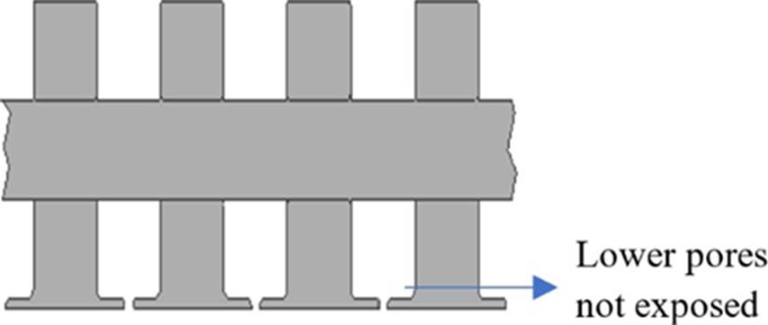
Figure 3 Side view of square geometry scaffolding with "elephant foot" effect (not to scale). Source: self-made.
It is possible to reduce this phenomenon by relying on Cura software [17]; however, this greatly hinders the adhesion of the material, which does not make its manufacture possible.
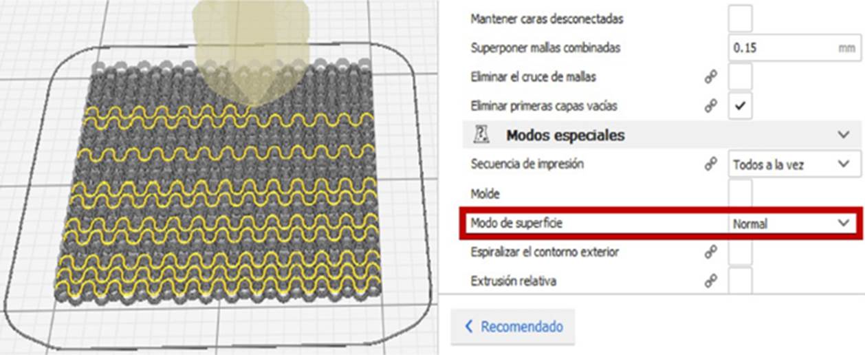
In the case of ellipsoidal scaffolding, it is evidenced that the way to print with precision, is to form each line with two thinner lines by using the option Special Modes-Surface: mode surface option [18] (Figure 4(A)) The normal option (used in the other geometries) doesn’t a satisfactory result (Figure 4(B)).
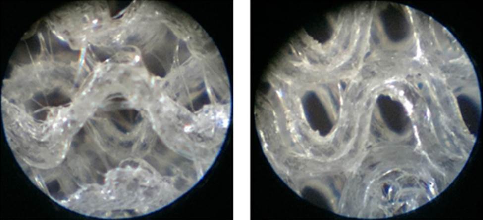
Figure 4 Ellipsoidal scaffolding. The images was taken from optical microscope with x50 magnification. Printed in surface option surface mode (two lines) (A). Printed in normal option surface mode (single line) (B). Source: self-made.
This phenomenon could be because on normal option, the extruder sometimes don’t print consecutively (printing the sections in Random form (Figure 5), which does not happen with the surface option.
The disadvantage of using two lines to form one is a thicker line results, so, the porosity of the scaffold decreases. To compensate part of this effect, the line is designed 0.01 mm smaller for this geometry.
Print parameters for PLA
Tables 6 and 7 show the parameters obtained for optimal printing of PLA scaffolds.
Table 6 Printing parameters for PLA scaffolds [17].
| Common print parameters for PLA geometries | |
|---|---|
| Parameter | Value |
| Layer height (mm) | 0.1 |
| Initial layer height (mm) | 0.1 |
| Line width1 (mm) | 0.18 |
| Print plate temperature (°C) | 60 |
| Horizontal expansion of the initial layer2 | -1 |
| Z seam alignment3 | User specified |
| Enable retraction | √ |
| Type of print plate adhesion4 | Skirt |
1Line width: The width of the nozzle in the software parameters is modified to 0.18 mm to force the printer to extrude less material than it should, remembering that the actual diameter is 0.2 mm, therefore the line width used is also in 0.18 mm.
2Horizontal expansion of the initial layer: this parameter is used at 0 by default, this produces the effect previously referred to as elephant foot to facilitate the adherence to the base. Using the value-1 decreases part of this effect. A value less than-1 makes it impossible for the material to adhere to the glass plate.
3Z seam alignment: this parameter uses the random option by default which causes the start seems to be generated in any sector. This decreases the print quality, because at the beginning of each layer the extruder deposits residues of the previous layer. The option specified by the user dictates the alignment of the seams at the same point for each layer, which favors the scaffold's print quality.
4Type of print plate adhesion: The skirt option draws a line around the scaffold, the residues of each print start to be deposited there and not affect the scaffolding.
Dimensions and porosity for PLA
Geometry
On average, all the geometries except the ellipse were approximately 50 µm smaller than the computationally modeled design. For the pore size of the ellipse to agree with that of the other geometries, an overlap had to be designed as shown Figure 6. A value of 100 µm was established to compensate for part of the material shrinkage.
Manufacturing observations for PCL
For the printing of the PCL scaffolds, it was necessary to install a hot plate on the base of the printer, to avoid the adhesion problems to the base for the rapid cooling suffered by the material. This phenomenon causes a contract and forms small drops that harden and modify the height printing. When this occurs, the needle passes through the sector again, it hits the drops, and the scaffolding comes off. Together with the previous point, other conditions to ensure surface adhesion, is the use of rough tape on the hot bed.
The pore width should be maintained between 300 and 600 µm since at the lower limit the filaments are joined and at the upper limit they are cut (Figure 8).
Print parameters for PCL
Table 9 shows the parameters obtained for optimal printing of PCL scaffolds.
Table 9 Printing parameters for PCL scaffolds [18].
| PCL | |
|---|---|
| Parameter | Square |
| Type of adhesion of the printing plate | Skirt |
| Layer Height (mm) | 0.2 |
| Initial layer height (mm) | 0.2 |
| Line Width (mm) | 0.3 |
| Print plate temperature1 (°C) | 25-35 |
| Line width initial layer % | 100 |
| Syringe temperature (°C) | 80 |
| Needle temperature (°C) | 75 |
| Flow % | 68 |
| Initial layer Flow % | 68 |
| Print speed (mm/s) | 10 |
| Ventilation speed% | Without ventilation |
1Print plate temperature °C: Change according to the ambient temperature; when ambient temperature is very low it is recommended to use 35 °C, when it is high, 25 °C.
Dimensions and porosity for PCL
Geometry
Due to the characteristics and temperatures at which the PCL was printed, it was deposited in a liquid state, and as a result, the material spreads occupying a larger surface compared to the computationally modeled design. This results in the pores that were designed to 400 µm being an average of 250 µm.
Porosity
Based on the above and considering the largest diameter of the extruder, the porosity was reduced to 34% for the square geometry. Figure 9 (A) shows a magnification of the final pore size. In Figure 10 it can see a 20 mm PLC scaffold.
CONCLUSIONS
The three-dimensional elaboration of scaffolding for the regeneration of cartilaginous tissue represents a challenge for the existing manufacturing market devices. From this study, it is concluded:
For the equipment used in this work, the pore size of PLA must be greater than 200 µm to prevent the effect called "elephant foot" enclosing the lower pores, while for manufacturing in PCL, the size of the computationally model pore should be greater than 300 µm to prevent the filament joining together and less than 600 µm, as the largest size, because the filaments will be cut.
It is necessary to consider the geometric design, the contraction of the geometries at least 50 µm for the PLA.
Particularly, for the ellipsoidal scaffolds of PLA, an overlap had to be designed to compensate the material retraction.
In PCL material, this difference is intensified, therefore, it should be considered that the computationally designed pore, decreases by approximately 150 µm in the final printed scaffold.
The extruder temperature is one of the most important variables. In PLA material, printing can be affected when the ambient temperature rises to 20 °C, the extruder temperature must be reduced below the manufacturer temperature indicates.
This is extremely important when printing is a very low speed. In PLC case, this is even more sensitive to temperatures, because it is a material that undergoes large retractions if it cools quickly, so it is necessary to implement a heat bed to the printing surface. On the other hand, the high temperature remains in a liquid state affecting the pore size.
As recommendations and future research work it is suggested:
The cell growth in manufactured geometries could be evaluated, to observe the incidence of the geometry and/or material in cell development.
The manufacturing options in the PLC case could be expanded, by using needles with smaller diameters, to obtain more porous scaffolds. Additionally, the possibility to combine PLC with another biocompatible material to improve its mechanical properties could be studied.
Cell growth evaluations could be carried out in the defective manufactured scaffolds. When the computationally modeled design was not obtained, the result geometry is an interspecific and random figure. This poorly arranged patterns environment may be beneficial for cell growth.

