


 nueva página del texto (beta)
 Inglés (pdf)
 Artículo en XML
 Referencias del artículo
 Enviar artículo por email
 Citado por SciELO
  Similares en
SciELO
Similares en
SciELO 
 Permalink
1. Introduction
The paper focuses on a Stirling engine that functions on the Stirling cycle principle. The said engine is a closed-type external combustion engine. Robert Stirling initially proposed Stirling Engine in 1817 to replace perilous steam engine [1].
Like any other heat engine cycle, the ideal Stirling cycle comprises of four discrete thermodynamic processes which are: isothermal expansion, isochoric heat removal, isothermal compression and isochoric heat addition. Stirling engines come in a variety of shapes; however, they are classified into three main configurations namely alpha, beta and gamma. Stirling engines are used in a variety of applications like solar energy [2,3], microchip chilling [4], Stirling engine powered submarines [5], household electric provision and temperature management [6], Stirling engine powered vehicles [7,8] and Stirling cryocooler [9].
Among smart materials, shape memory alloys (SMAs) are frequently utilized due to their unique characteristics, and they are widely used in scientific research and various industrial applications, including biomedical devices and the automation and robotic industries [10]. These materials have a distinctive characteristic of remembering their original shape under external load (super-elastic) or thermo-mechanical load (shape memory effect) [11]. SMA elements can be of a variety of forms (strips, rods, sheets, wires, springs, tubes) which come in various sizes [12]. In the research that follows, spring shaped Nitinol is used.
In this paper, the Stirling engine has been modified with a shape memory alloy (Nitinol) and its output parameters have been studied and compared.
2. Experimental setup
Gamma Stirling engine has been modified with a shape memory alloy (Nitinol) and the nomenclature for the new engine has been coined as Stirnol engine. The amalgamation of both dimensions is conducted to find out if the shape memory effect of Nitinol enhances the output efficiency of Stirnol engine. The shape of Nitinol in this study is a spring, which is adapted to the Stirling engine.
The Nitinol spring, which operates within the temperature range of 30-60°C, is employed in the engine, enhancing its output power and efficiency by expanding and contracting as required. The Martensitic finish temperature (M f ) and Austenitic finish temperatures (A f ) values of Nitinol spring used are 30°C and 60°C respectively and the temperature range inside the Stirling engine is also observed to be from 40°C to 60°C. The said temperature is considered ideal for Nitinol spring to expand and contract inside the Stirling engine.
Some physical parameters of Nitinol spring employed in the experimental setup are shown in Table I.
Table I Nitinol spring dimensions.
| S No. | Dimensions | Value |
|---|---|---|
| 1 | Diameter | 9 mm |
| 2 | Wire thickness | 0.7 mm |
| 3 | M f (Martensitic finish temperature) | 30°C |
| 4 | A f (Austenitic finish temperature) | 60°C |
To measure the enhancement in efficiency of Stirlingengine, the efficiencies of both gamma Stirling engine and Stirnol engine are calculated and a comparative study has been carried out. In this regard, two engines were constructed with similar dimensions; one with Nitinol spring modification titled Stirnol engine and the other one a simple gamma Stirling engine. The aim is to apply same temperature difference to both engines and eventually check their output parameters.
2.1. Modification from Stirling engine to Stirnol engine
The modification which differentiates the Stirnol engine from Stirling engine is presence of Nitinol spring. To incorporate an SMA spring in the engine, a threaded Aluminum part is manufactured [Fig. 1b)]. The part is threaded from inside so that it can hold the spring. Once the lower plate of engine is heated, the spring expands and contracts thus adding force to the displacer to operate. To incorporate the SMA spring, a threaded aluminum part shaped like a holding cup is manufactured and assembled inside the lower plate in a push-tight arrangement to prevent air leakage, which can decrease the efficiency of the Stirnol engine. The complete arrangement of Stirnol engine is shown in Fig. 1, with its dimensions depicted in Table II.
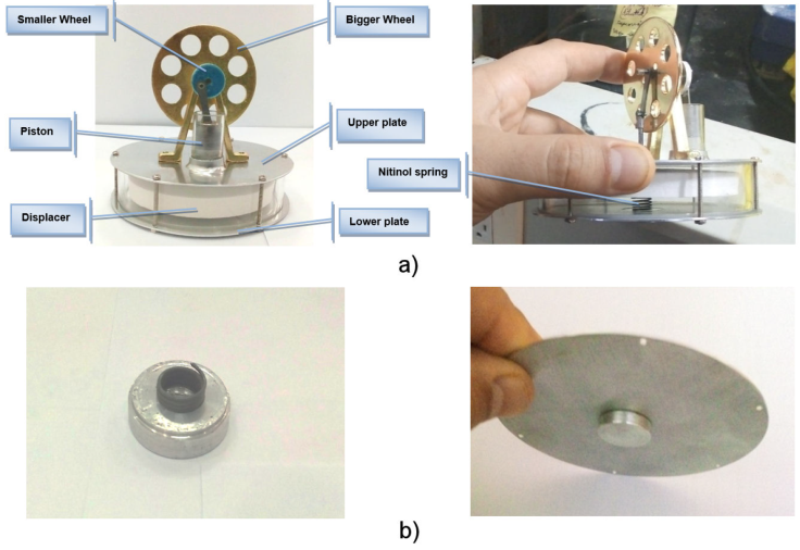
Figure 1 a) Experimental Stirnol engine-modified by attaching Nitinol spring. b) Attachment of Nitinol spring with lower plate of Stirling engine.
Table II Dimensions of experimental Stirnol engine.
| S No. | Dimensions | Values |
|---|---|---|
| 1 | Diameter of Upper and Lower plates | 9.7 cm |
| 2 | Thickness of Upper and Lower plates | 01 mm |
| 3 | Diameter of Displacer | 08 cm |
| 4 | Thickness of Displacer | 01 cm |
| 5 | Height of Piston | 1.5 cm |
| 6 | Diameter of Piston | 1.2 cm |
| 7 | Diameter of Bigger Wheel | 5.3 cm |
| 8 | Diameter of Smaller Wheel | 1.5 cm |
| 9 | Diameter of Aluminum Cup | 02 cm |
| 10 | Height of Aluminum Cup | 0.5 cm |
| 11 | Diameter of Nitinol Spring | 09 mm |
| 12 | Height of Nitinol Spring | 0.5 cm |
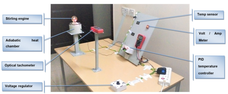
2.2. Experimental testing facility
The testing facility as shown in Fig. 2 was developed to analyze both engines. The engines were provided heat inan adiabatic heating chamber which had an inner lining of polyurethane. A Proportional Integral Derivative (PID) temperature controller was incorporated to achieve the desired temperature values. The temperature difference was gradually increased and behaviour of Stirnol engine was observed. The efficiency of both engines was calculated using a tachometer and results of both engines are elaborated in analysis section.
3. Theory of Stirnol engine
The cyclic theory of Low Temperature Difference (LTD) Stirnol engine is presented which induces flow compression, expansion and regeneration (through displacer) in free volume. The preliminary results show slight efficiency improvement due to addition of Nitinol spring.
3.1. The Stirling cycle vs Stirnol cycle
The fundamental principle behind many thermal machines is the thermodynamic power cycle, which involves converting internal energy into mechanical work. The Stirling engine is one such machine that operates on a four-stage closed regenerative cycle. Robert Stirling’s innovative concept for his machine included a heat exchanger that captured some of the energy from the heated gas exiting the expansion chamber, and then released it when the cold gas returned to the chamber. This component is now known as the ’regenerator’, which in the LTD Stirling engine is fulfilled by the displacer.
In the Stirling engine, an ideal gas or heating substance undergoes a series of expansions and compressions as it exchanges heat with hot and cold temperature sources. This process involves four distinct thermodynamic stages, and the following paragraphs provide a detailed account of each step and how the Nitinol spring affects the overall operation of the engine. Additionally, the graphical representation of this process can be found in Fig. 3.
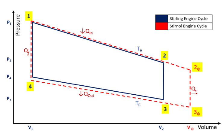
Figure 3 Theoretical graph depicting possible effects of installation of Nitinol spring in Stirling engine
1st Process. The process of isothermal expansion or spring extraction occurs in the Stirling engine during steps 1-2 when the gas is heated from an external source. In the Stirnol engine, this process is enhanced by the Nitinol spring’s extractive motion, which expands upon heating and can theoretically extend the process beyond point 2 to Φ2.
2nd Process. The process of isochoric heat removal occurs in both the Stirling and Stirnol engines during steps 2-3, where the gas transfers heat to the displacer and undergoes a process of isochoric cooling.
3rd Process. The process of isothermal compression or spring retraction occurs in the Stirling engine during steps 3-4 as the gas undergoes isothermal compression and transfers heat to the cool temperature source. In the case of Stirnol engine, there are three possibilities at this stage.
The Nitinol spring’s shape memory alloy properties allow it to retract to its original shape and size without affecting this phase of the engine.
The Stirnol engine would waste some work in compressing the Nitinol spring because the downward movement of the displacer must overcome the partial spring force that is already retracting due to the decrease in temperature.
Nitinol spring could be relocated and attached to the displacer, whereby it could exert a pulling force on the piston, enhancing the motion of the retraction stroke. However, due to design limitations of the Stirnol engine, this was not possible.
4th Process. The compressed gas receives heat from the regenerator and undergoes a process of isochoric heat addition during steps 1-4.
4. Results and discussions
Stirling engine’s thermal efficiency is determined by the ratio of its power output to the amount of heat transferred from high-temperature source. Schmidt developed a model to predict the power output of a Stirling machine [13-15]. Furthermore, Chen and Giffin [16] identified 25 different models of Stirling engines. Beale proposed an empirical equation and for the first time introduced the dimensionless parameter Bn called Beale number [17]. For Low temperature difference Stirling engines, Walker [1] proposed his own empirical equation. Senft attested that the prospect to run an engine continuously with a temperature difference of only 0.5°C and ΔT of about 30°C is a good practical limit to produce mechanical power (e.g., using solar energy or waste heat from air conditioning systems) [18].
Kongtragool [19] suggested using the modified Beale number equation:
The typical values for
To measure the performance of Stirnol and Stirling engines, a testing facility was constructed (Fig. 2). The very low power figures made it compulsory to adopt typical testing designs to measure brake power and heat transfer from the high temperature source, without using expensive laboratory instruments. The testing procedure involved supplying heat
Three parameters, namely rotational speed, efficiency, and brake power were calculated and plotted.
4.1. Temperature difference vs RPM
The comparison of temperature difference vs RPM of Stirling and Stirnol engines is endorsed in Table III and graphically illustrated in Fig. 4.
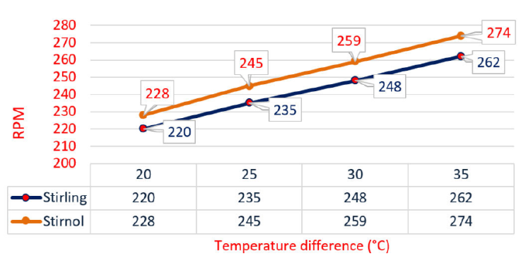
Figure 4 Performance comparison in terms of RPM generated by Stirling and Stirnol engines at various temperature differences.
Figure 4 illustrates that overall RPM of the engine has improved with addition of an SMA.
To ensure that both engines were exposed to similar temperatures, heat was evenly distributed, and temperature differences were kept constant using a PID temperature controller (Fig. 2). The flywheel RPM of both engines was calculated by means of a laser-operated tachometer. The experimental results reveal that RPM of Stirnol engine is enhanced by approx. 10 RPM at each temperature difference value as compared to Stirling engine.
4.2. Brake power vs RPM
The brake power of an IC engine refers to the power available at its crankshaft, and it can be determined using the formula:
The comparison of brake power vs RPM of Stirling and Stirnol engines is depicted in tabulated form in Table IV and graphically illustrated in Fig. 5.
Table IV Brake Power vs RPM of Stirling and Stirnol engines at various temperature differences.
| S No. | Temp diff (°C) | Stirling engine | Stirnol engine | ||
|---|---|---|---|---|---|
| RPM |
|
RPM |
|
||
| 1 | 20 | 220 | 0 | 228 | 0 |
| 190 | 1.3 | 200 | 1.5 | ||
| 115 | 2.2 | 130 | 2.5 | ||
| 70 | 2.0 | 77 | 2.4 | ||
| 35 | 1.5 | 41 | 1.9 | ||
| 2 | 25 | 235 | 0 | 245 | 0 |
| 218 | 1.35 | 224 | 1.6 | ||
| 150 | 2.7 | 158 | 3.0 | ||
| 100 | 2.9 | 110 | 3.3 | ||
| 40 | 2.3 | 47 | 2.5 | ||
| 3 | 30 | 248 | 0 | 259 | 0 |
| 232 | 1.43 | 241 | 1.5 | ||
| 160 | 3.15 | 168 | 3.3 | ||
| 100 | 3.3 | 109 | 3.2 | ||
| 33 | 2.4 | 39 | 2.7 | ||
| 4 | 35 | 262 | 0 | 274 | 0 |
| 240 | 1.65 | 252 | 1.9 | ||
| 170 | 3.5 | 178 | 3.8 | ||
| 105 | 3.65 | 112 | 3.7 | ||
| 40 | 3.0 | 47 | 3.4 | ||
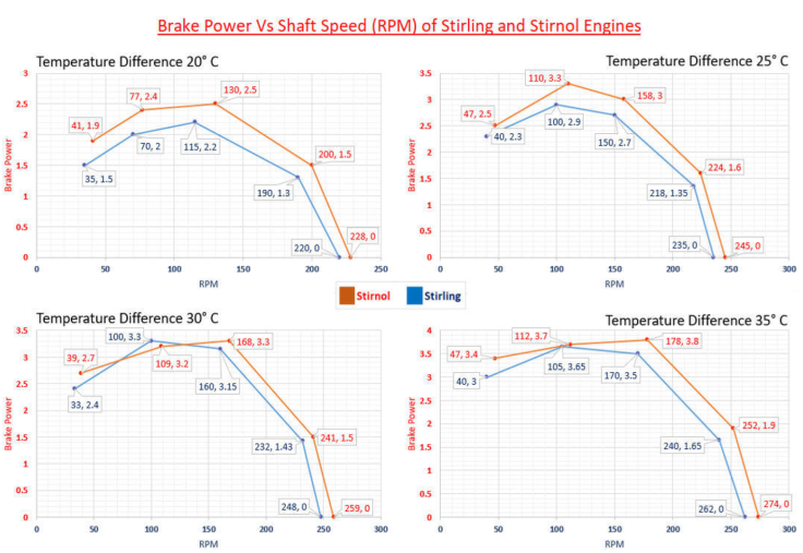
Figure 5 Graphical representation of comparative brake power vs shaft speed (RPM) of Stirling and Stirnol engines at various temperature differences.
Brake power represents the engine’s output shaft power, which is traditionally considered the definitive measurement of engine power, as it accounts for power loss due to friction.
To measure brake power, the engine is run up to full revolutions and then allowed to slow down naturally until it comes to a complete stop.
The graphical representation of brake power of both the engines reveal that till 180 RPM, both the engines behaved similarly; however, Stirnol engine displayed some unexpected behaviour above 180 RPM. It might be because of out of sync movement of Nitinol spring with respect to the displacer.
4.3. Analysis of engine efficiency vs RPM
The formula for calculating thermal efficiency is:
The comparison of engine efficiency vs RPM of Stirling and Stirnol engines is depicted in tabulated form in Table V and graphically illustrated in Fig. 6.
Table V Engine efficiency vs RPM of Stirling and Stirnol engines at various temperature differences.
| S No. | Temp diff (°C) | Stirling engine | Stirnol engine | ||
|---|---|---|---|---|---|
| RPM | Efficiency (%) | RPM | Efficiency (%) | ||
| 190 | 0.025 | 205 | 0.029 | ||
| 115 | 0.047 | 120 | 0.063 | ||
| 1 | 20 | 65 | 0.045 | 72 | 0.057 |
| 35 | 0.032 | 42 | 0.034 | ||
| 215 | 0.03 | 225 | 0.035 | ||
| 155 | 0.064 | 164 | 0.07 | ||
| 2 | 25 | 100 | 0.07 | 108 | 0.075 |
| 60 | 0.058 | 66 | 0.06 | ||
| 235 | 0.031 | 247 | 0.039 | ||
| 160 | 0.068 | 169 | 0.08 | ||
| 3 | 30 | 110 | 0.078 | 117 | 0.09 |
| 60 | 0.063 | 65 | 0.07 | ||
| 250 | 0.032 | 263 | 0.03 | ||
| 165 | 0.072 | 172 | 0.074 | ||
| 4 | 35 | 105 | 0.09 | 112 | 0.1 |
| 50 | 0.07 | 57 | 0.074 | ||
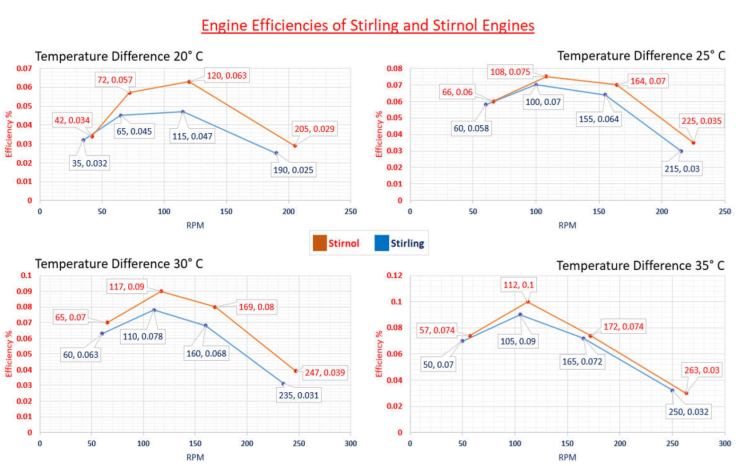
Figure 6 Graphical representation of comparative engine efficiencies of Stirling and Stirnol engines at various temperature differences.
While the engines exhibited less efficiency than the Carnot cycle, the Nitinol spring’s presence has improved it. However, when temperature difference reached approximately 35°C, efficiency of Stirnol engine was unexpected.
5. Conclusion
The research concludes that combining the two domains of physics can produce better and more beneficial results. By incorporating an SMA (Nitinol spring) into the Stirling engine, the properties of SMAs can be better utilized to enhance the basic Stirling cycle’s efficiency at lower temperature differences. To ensure consistency, both engines had similar geometry / arrangements and were subjected to similar temperature differences in a testing facility. The RPM, efficiency, and brake power were calculated as parameters in the experimentation. Comparison of these parameters is as follows:
RPM. Within the temperature difference range of 20-35°C, RPM of Stirnol engine was found to be approximately 10 revolutions more than that of Stirling engine. This reveals that increase in RPM is only due to presence of SMA (Nitinol spring).
Brake power. Brake power of Stirnol engine was found consistent till 180 RPM. Above the said value, Stirnol engine exhibited some abrupt changes which need to be further investigated.
Efficiency. Within the temperature difference range of 20-35°C, the efficiency of Stirnol engine has shown improvement as compared to Stirling engine. The said engines are very simple in geometry and an increase of this minimal efficiency can be considered humongous. With the advancement in complexity and further optimization in modification of Stirnol engine, it is expected that efficiency may be further enhanced.
These outputs can be applied to various applications in the future. By systematically and rationally varying geometric and physical parameters, heat transfer and fluid flows can be computed. This research paper identifies a genuine improvement in real machine operation and paves the way for further optimization. Additionally, this operation will aid in modifying the experimental setup and, more importantly, selecting the SMA material and geometry.

