


 nueva página del texto (beta)
 Inglés (pdf)
 Artículo en XML
 Referencias del artículo
 Enviar artículo por email
 Citado por SciELO
  Similares en
SciELO
Similares en
SciELO 
 Permalink
1. Introduction
The supersonic nozzles find their application in several sectors of the research and industry, such as aerospace, turbomachinery and refrigeration engineering [1-3]. The area of spatial propulsion is specifically potential since the nozzle is among the vital components of a launcher. Indeed, for nozzles with high area ratio, the specific impulse is improved, allowing therefore for payload enhancement and launching cost reduction [4-5]. However, the internal supersonic flow is subjected to several instabilities as it operates under overexpanding conditions for almost all the mission steps [5]. As the flow develops within the divergent part of the nozzle, local free (FSS) or restricted (RSS) separation may occur inducing side loads, that can alter the structural integrity of the nozzle as well as launcher performances reduction [4,6].
The physics of flow separation remains not fully understood despite the abundance of experimental and numerical investigations on the effect of nozzle geometry (CV, DV, CV-DV junction) on shock separation appearance [7]. The developed models exhibited a lack of accuracy regarding the prediction of the position of separation, while they provided few analyses on the flow pattern downstream the separation zone.
Attempts to correlate between divergent geometry and flow morphology have been conducted for more than fifty years. The investigations on the method of characteristics (MOC) allowed for the prediction of the dynamic field in the kernel zone, providing also a practical way for divergent wall profile design [8].
Many authors focused on the sonic line curvature at the throat region and how it could influence the flow pattern at the nozzle exit. The investigations have concerned several European and US rocket nozzles and revealed the direct relation between the throat region flatness and the exit Mach number [9,10].
For several types of nozzle profiles, a variety of physical criteria for the prediction of the flow separation have been numerically provided and made available for the manufacturers [11]. These attempts focused on the effect of stagnation pressure of the separation appearance, without any accurate prediction of its position. To overcome these difficulties, many investigations were oriented on the convergent and/or divergent design approaches, i.e., the so-called passive techniques.
The investigations have continued with an interest to the transonic region curvature, with the works of Cuffel et al [11]. The experimentations have revealed the existence of a limiting value for the CV-DV connecting arc radius, which allowed for a quasi-1D flow on the throat region, ensuring therefore an expansion flow without separation in the conical divergent.
Applications of passive techniques on propulsion raised with some developed novel curved shapes, discussed by Ho et al. on the contraction part of nozzles [13]. In their investigation, the authors have succeeded in simulating laminar and inviscid flows in simply convergent nozzles and have shown that flat profiles of velocity at the exit section could be obtained for different values of the flatness parameter. The investigation focused on the shape of the sonic line at the throat region, while quantifying the corresponding discharge coefficient at the nozzle exit section.
Similar analyzes were carried out by Brassard et al. on curved convergent profiles, composed of two circular arcs [14]. The analyses revealed the importance of the inflection point position on the value of the dynamic uniformity index at the convergent exit section. No analysis has been provided on the flow pattern downstream the throat region.
The influence of the convergent design parameters on the sonic line curvature was recently investigated by Germer et al [15]. For the case of an inviscid flow, the authors highlighted the effects of the angle at the convergent inlet, the radius upstream and downstream the throat on the curve flatness of the Mach number distribution curve at the throat region. The study was not interested on the morphology of the expansion flow within the conical divergent.
Kumar et al. have investigated the flow configuration on a curved convergent based on polynomial profiles [16]. The authors were interested in the minimization of pressure losses on an inert fluid flow, using several degrees of interpolation, with no analysis or information on flow separation.
The present study deals with a numerical prediction of a free shock separation (FSS) within an overexpanded experimental nozzle. A preliminary control of the separation position by acting on the convergent curvature was discussed. Using four profiles for the design of the convergent (error function), a comparative study is performed to seek for the contraction shape that reproduces the highest thrust coefficient while keeping the shock separation as far as possible from the throat region. Favre averaged forms of the Navier-Stokes equations are numerically solved by means of a finite volume software. Turbulent viscosity transport is handled with the Spalart-Allmaras model whereas a Roe scheme is used for the convective fluxes terms.
2. Contraction design formulation
Over the years, many authors have been interested in methods of designing contractions for wind tunnels and nozzles. The present work deals with a design formulation for the convergent part, based on minimum length (MLN) techniques [13]. For inviscid and supersonic flows in a nozzle, a single function
To help ensure a planar sonic surface with a uniform velocity, several derivatives of
With the constraints above, one seeks a function that also satisfies
where
and
where σ = 0 for planar flows and σ = 1 for axisymmetric flows. The expression above, represents a single, flexible, analytic function that defines the contraction shape, where
3. Flow equations
Within the calculation domain, the fluid is non reactive (GN2), having constant thermophysical properties (specific heat capacity, thermal conductivity). The mathematical formulation of the principles of conservation of mass, momentum and energy, associated with the physical properties for a compressible axisymmetric, viscous fluid is expressed in the following form:
where:
The stress and heat-transfer components are the sum of viscous and turbulent contributions. Hence, the source term for the flow is
The thrust is generated by two parts of the rocket engine, namely the combustion chamber and the divergent nozzle. The important parameter for rocket design is the thrust coefficient
4. Test facility and experimental data
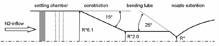
The test data were obtained at DLR’s cold flow test facility P6.2 in Lampoldshausen, Germany [18,19]. A dry gaseous nitrogen is used and stored in high pressure tanks outside the facility. The advantage of nitrogen compared to air is the absence of water vapour that tends to condense. The inert gas flows across a cylindrical settling chamber and cross-section constriction before it accelerates in a convergent- divergent nozzle to a supersonic velocity (Fig. 1), according to an operating NPR=25.25 [19,20].
5. Numerical computations
5.1. The computational domain and grid generation
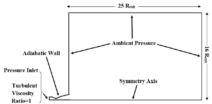
The computational domain consists of half of the DLR nozzle with its real dimensions, attached to a far- field inflow “virtual box”, making it possible to capture possible oblique shocks (Fig. 2). It is important to stress that the baseline simulation considers a directly replicated contour of the nozzle convergent, as it was featured in the experimental facility [18].
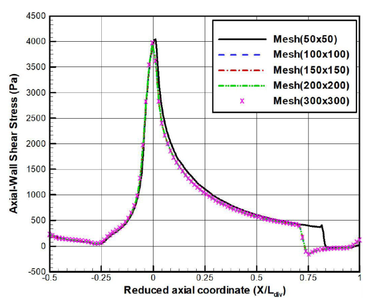
The nozzle inflow was filled with a structural grid containing 200 × 200 cells in both axial and radial directions. The turbulent boundary layer was resolved by a gradually fine mesh where
5.2. Boundary conditions
As a working fluid, dry gaseous nitrogen
5.3. Turbulence modelling
The standard turbulence model used in the simulations is the Spalart-Allmaras model [23].
5.4. Discussions
The used CFD solver is based on the compressible Favre averaged Navier-Stokes equations, associated with turbulent closures. The spatial discretization is a second-order accurate both for the viscous and inviscid terms, where the latter are computed based on a Roe scheme [24].
For the nozzle geometry (baseline) used in the experimental tests [19], the numerical simulation shows a free shock separation which locates upstream of the exit section of the divergent nozzle. The flow pattern is followed by the appearance of a Mach disc downstream the separation zone (Fig. 4), which is commonly a well-known trend of an overexpanded flow.
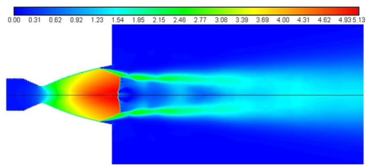
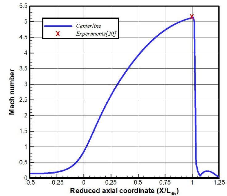
Across the nozzle centerline, the Mach number exhibits a monotonous evolution in the convergent part of the nozzle, with a throat value
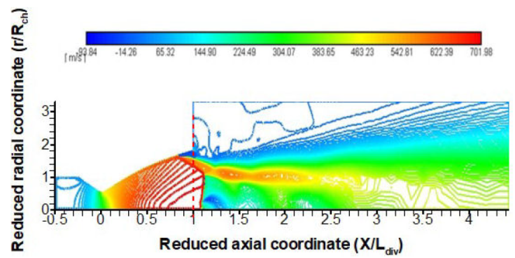
The spatial contour of the axial velocity clearly showsa free shock separation (FSS) in the upstream region of the nozzle exit section (Fig. 6). The flow separation exhibits an oblique shock followed by a normal shock in the vicinity of exit section. A strong shear region is clearly depicted in the post-separation zone where an intense recirculation occurs.
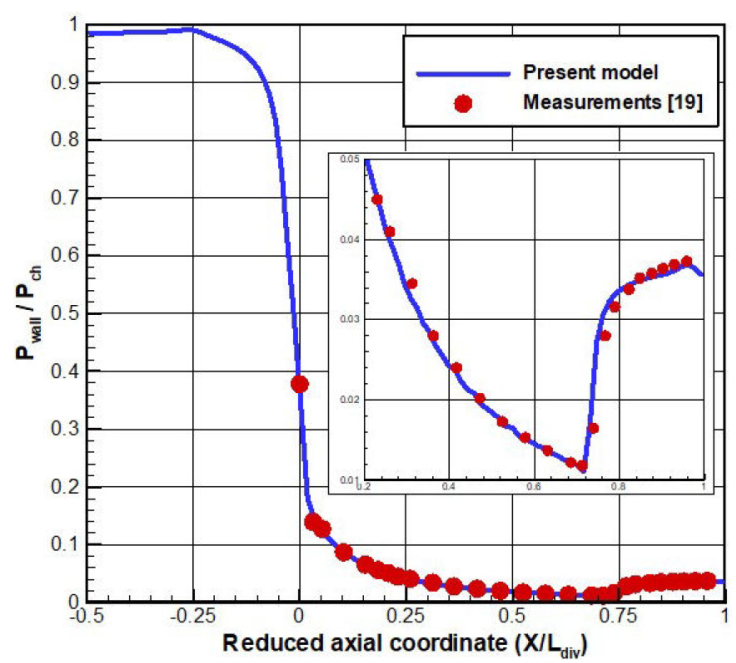
The evolution of the predicted wall static pressure recovers a slight recompression upstream of the nozzle exit which physically reveals a local flow separation (Fig. 7). Accordingly, the comparison between the numerical values and the local measurements on the nozzle wall is fairly satisfactory.
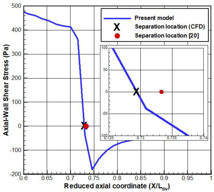
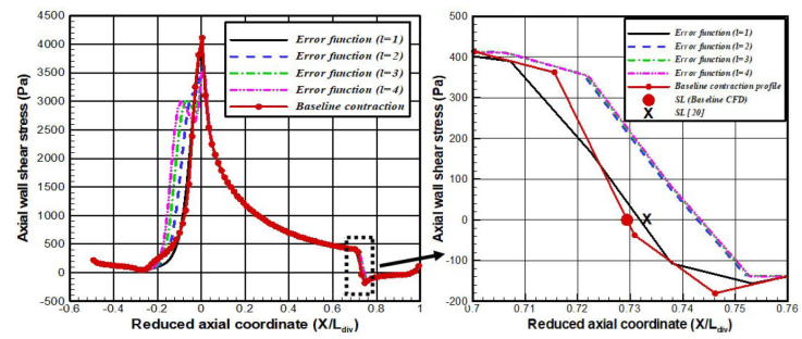
The location of the separation point can be predicted according to the axial wall shear stress evolution (Fig. 8). A steep decay of the corresponding curve reveals a relaxation of the boundary, which separates upstream the divergent exit. The curve reaches a zero value and becomes negative owing to the pressure gradient effects. The predicted separation location
It is important to stress that an intense recirculation zone is developed in the vicinity of the divergent wall, right downstream the separation point. An oblique shock is initiated with the formation of a sliding line that splits between the core flow and the backflow (Figs. 9, 10).
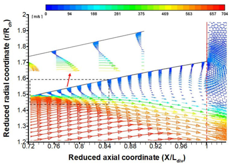
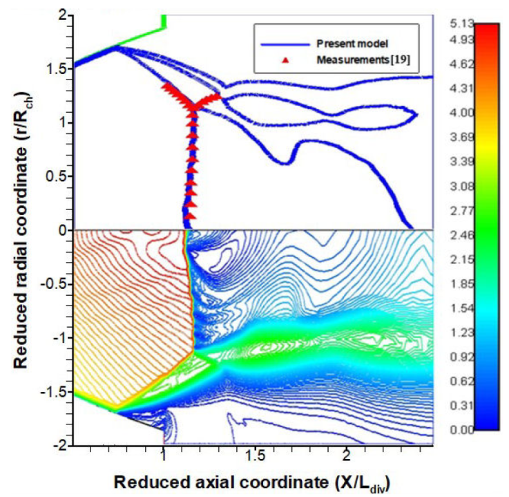
Accordingly, the spatial contour of the Mach number clearly shows the different zones around the separation (Fig. 10).
In comparison with the available experimental data, the numerical values for the Mach number exhibit a good agreement, with a relative deviation less than
With such flow recirculation in the post-separation zone, the exit stream is no longer parallel to the nozzle axis. Consequently, a radial gradient of the exit velocity is noticed, which has the effect of altering the value of the thrust coefficient Table I, in comparison with the adaptation (ideal) case, where the nozzle inflow expands up to a pressure equilibrium state with the far-field flow.
Table I Thrust coefficient values for several exit conditions.
| cases | Adaptation | Design point [20] | Present model |
|---|---|---|---|
| Thrust coefficient (CF) | 1.5701 | 1.6538 | 1.0299 |
Table I depicts several thrust coefficient values, with regards to the conditions
In the following calculations, geometrical variants of the TIC-DLR nozzle will be generated according to the contraction profiles. The baseline data
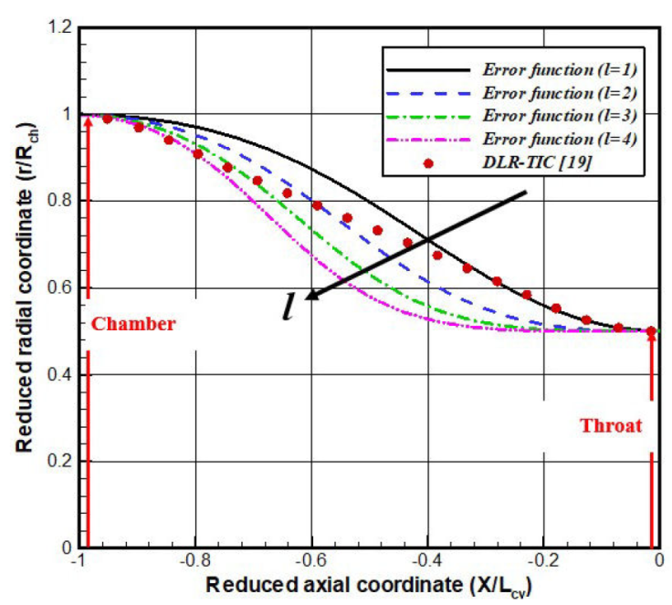
It is worthy noticing that the design parameter l is the only factor which controls the flatness of the generated profiles. For high l values, the contraction variants exhibit a strong inflection at the central region, while their flattening at the geometric throat, is highly improved Fig. 11. A sensitivity analysis revealed that curvatures of the convergent variants become nearly identical, for values of the flatness coefficient greater than l = 5 [21].
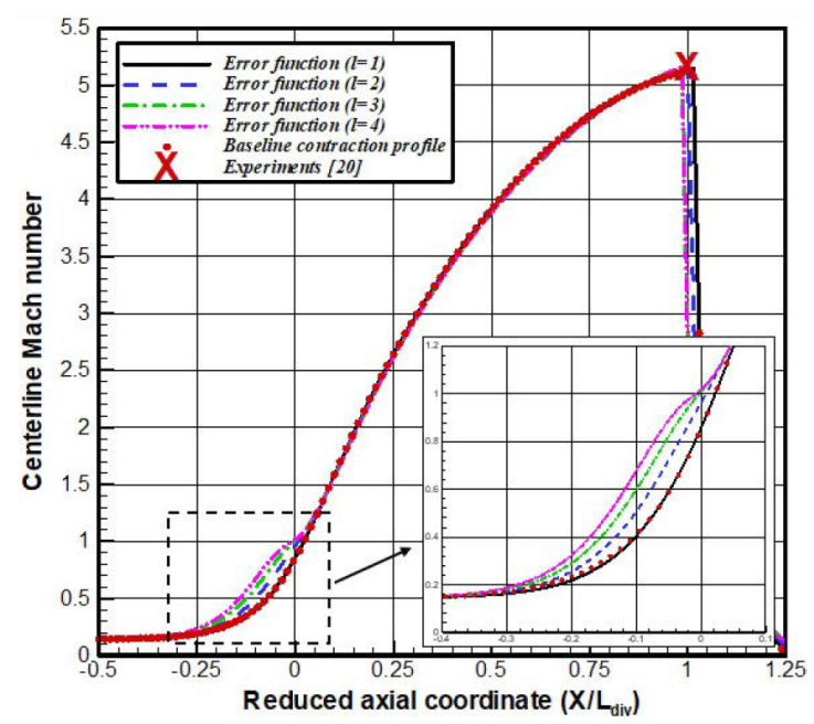
In the convergent part of the nozzle, the use of several variants induces small changes of the centerline Mach number (Fig. 12). Indeed, one notice an increase in the Mach number values as well as the flatness parameter is high, specifically in the throat upstream region. The contraction variant with l = 1 coincides perfectly with the baseline (experimental) profile. It is an important to mention note that the profile variant with l = 4 recovers exactly a sonic condition (Mach = 1) at the geometrical throat of the nozzle, in contrast to the other variants for which the flow remains subsonic. However, the supersonic core-flow in the divergent part of the nozzle, remains slightly sensitive to the contraction profile variants, with nearly identical exit Mach numbers.
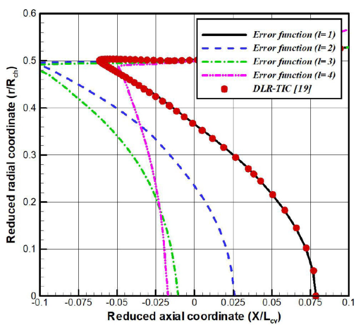
Focusing on the throat section, the radial evolution of the Mach = 1 lines is represented in Fig. 13. It is quite clear that the baseline profile as well as the variants with l = 1 and l = 2 recovers a sonic Mach number
This behavior is also depicted in spatial contours of the Mach number, for the baseline (top) and the variant l = 4 (bottom) contraction profiles (Fig. 15). The figure below clearly shows that both the oblique and normal shocks for the error function profile (l = 4) are located downstream their baseline location.
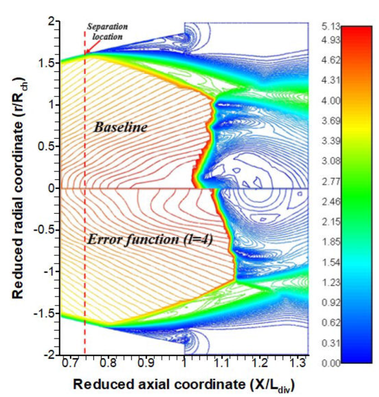
Figure 15 Mach number contour (baseline-top & l = 4-bottom contraction profiles) near the separation.
As the flow separation location moves downstream with the increase of the contraction profile flatness, the core-flow is believed to be an “undisturbed” region of the expanding stream. Consequently, the flow momentum increases as the upstream zone of the separation enlarges, allowing therefore an improvement the nozzle thrust.
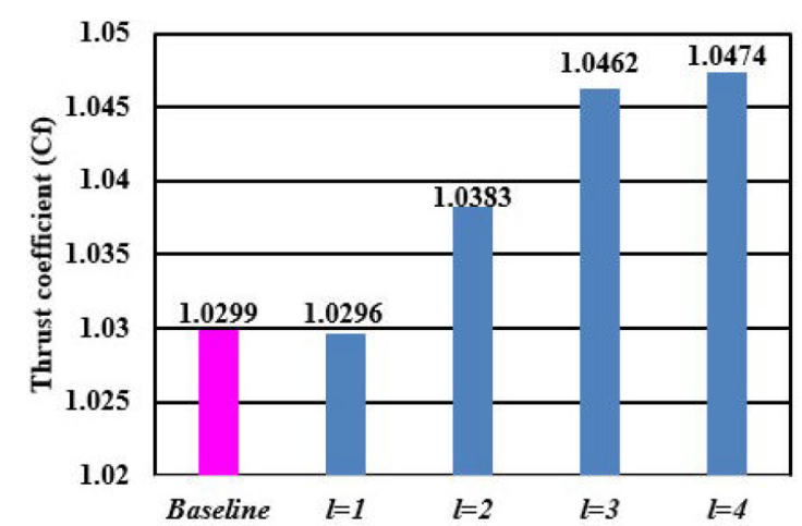
Figure 16 depicts several thrust coefficient values with regard to separation locations. It is worthy noticing that the profile variant with l = 1 provides almost the same thrust as the baseline case. This insignificant discrepancy was expected since this variant exhibits the same patterns for the sonic line and the separation location as the baseline profile. The contraction profile with l = 4 shows a relative improvement of +1.7% on the thrust coefficient, compared to the baseline case. The thrust coefficient is this overexpanded case still remains below its ideal value, obtained for the adaptation exit condition.
6. Conclusion
A set of contraction curves were investigated numerically in the aim to control the shock waves and the separation location in an overexpanded nozzle. In this direction, wall static pressure, separation location, Mach disk and shock structure were validated and compared with the DLR experimental data, provided by the nozzle test-rig.
The main conclusions of this CFD analysis can be drawn as follows:
There was a good agreement between numerical results for the baseline case, and the DLR measurements.
The flatness of the contraction was more pronounced in the vicinity of the throat, with the increase of the parameter (l).
The contraction profile with l = 4, was the most interesting specific case, which recovers a quasi- straight sonic line and moved the separation location (SL) towards the exit direction.
It was stressed that the contraction profile with l = 4 showed a relative improvement of +1.7% on the thrust coefficient, in comparison to the baseline profile.
| Nomenclature | |||
| A | Cross sectional area | v | kinematic viscosity |
| C f | Thrust coefficient | τ | Viscous stress tensor |
| D | diameter | Subscripts | |
| F | nozzle thrust | a | ambient |
| l | flatness coefficient | ch | chamber |
| Lcv | convergent length | e | exit |
| Ldiv | divergent length | th | throat |
| M | Mach number | w | wall |
| P | static pressure | Abbreviations | |
| R | radius | CFD | computational fluid dynamics |
| r | Radial coordinate | CV | convergent nozzle |
| T | static temperature | CV-DV | convergent-divergent nozzle |
| u x | axial velocity | DLR | German Aerospace Center |
| u r | radial velocity | DV | divergent nozzle |
| X | axial coordinate | FSS | free shock separation |
| Y+ | Wall Yplus | MLN | minimum length nozzle |
| Greek symbols | MOC | method of characteristics | |
| γ | Specific heat ratio | NPR | nozzle pressure ratio |
| μ | dynamic viscosity | RSS | restricted shock separation |
| ρ | density | SL | separation location |
| σ | normal stress tensor | TIC | truncated ideal contoured nozzle |

