


Serviços Personalizados
Journal

Artigo
 Inglês (pdf)
 Artigo em XML
 Referências do artigo
 Enviar este artigo por email
Indicadores
 Citado por SciELO
 Links relacionados
-
 Similares em
SciELO
Similares em
SciELO
Compartilhar

 Permalink
Geofísica internacional
versão On-line ISSN 2954-436Xversão impressa ISSN 0016-7169
Geofís. Intl vol.46 no.4 Ciudad de México Out./Dez. 2007
Article
Scattering of Rayleigh–waves by surface–breaking cracks: an integral formulation
A. Rodríguez–Castellanos1, R. Ávila–Carrera1 and F. J. Sánchez–Sesma2
1 Instituto Mexicano del Petróleo (IMP), Eje Central L. Cárdenas 152, Ed. 27. Ofna. NJ3C; Tel. 01(55)9175–7015, Fax. 01(55)9175–8295, Del. Gustavo A. Madero, 07730 México City, México. Email: arcastel@imp.mx *Corresponding author: rcarrer@imp.mx
2 Instituto de Ingeniería, Universidad Nacional Autónoma de México, Del. Coyoacán, 04510 México City, México. Email: sesma@servidor.unam.mx
Received: January 22, 2007
Accepted: June 22, 2007
Resumen
Se estudia la difracción de ondas de Rayleigh debida a grietas rompientes en superficie. Se consideran varias configuraciones y profundidades para mostrar la importancia de la geometría de las grietas en la propagación de las ondas de Rayleigh. Para este fin, empleamos el Método Indirecto de Elementos Frontera. Esta técnica numérica se basa en una representación integral del campo difractado, el cual se deduce de la identidad de Somigliana. Este método permite evaluar el campo total de desplazamientos mediante la superposición de un campo libre y un campo difractado. Para el caso que nos ocupa en este trabajo, el campo libre se encuentra descrito por ondas de Rayleigh en un medio hipotético (sin la presencia de grietas) y el campo difractado se obtiene a partir de la solución integral tomando en cuenta la presencia de las grietas. Nuestros resultados se comparan con estudios previos. Enfatizamos las reducciones y amplificaciones que sufren las ondas de Rayleigh al interactuar con las grietas. Consideramos que esta información puede ser de gran utilidad a la comunidad científica, pues se busca describir la importancia de los parámetros como la profundidad y orientación de las grietas. El estudio aquí presentado permite caracterizar un grupo de grietas rompientes a partir del análisis del campo difractado.
Palabras clave: Ondas de Rayleigh, propagación de ondas, grietas rompientes, difracción.
Abstract
Several crack configurations are considered in order to show the importance of the cracks' geometry on the Rayleigh–wave propagation. We use the Indirect Boundary Element Method, this numerical technique is based on an integral representation of the diffracted wave field, which has been reduced from Somigliana's identity. The method allows us to evaluate the complete displacement field by the superposition of the free field and the diffracted field. It is remarkable that the free field is specified as incident Rayleigh– waves, making the assumption of absence of cracks. The diffracted field is obtained from the integral representation by means of the presence of cracks. Our results are compared with those previously published. We emphasize the amplitude reduction of Rayleigh– waves while the interaction with the cracks take place. Conspicuous wave amplification at the crack neighborhood is observed immediately after such interaction. This information may give us a way to characterize crack's depth and orientations from the analysis of the diffracted field.
Key words: Rayleigh waves, wave propagation, surface–breaking cracks, diffraction.
Introduction
Elastic surface waves, also called surface acoustic waves, were discovered in 1885 by Lord Rayleigh (1885). In infinite elastic medium, the longitudinal and transverse waves (P– and S– waves, respectively) are independent and propagate with different velocities, but in surface waves the longitudinal and transverse waves are coupled. Surface waves also differ from P– and S–waves in their propagation velocity. The Rayleigh–wave velocity is about 5 to 13% smaller than S–wave velocity and mainly depends on the Poisson's ratio (Hess, 2002). In a two–dimensional propagation problem that contains a free surface, Rayleigh–waves are more dominant than P– or S–waves (Wong, 1982). This is due to the retrograde nature of motion of Rayleigh–waves. Such type of motion has been considered to be the main cause for many damages (e.g. seismic problems). It is well known that an important feature of Rayleigh–waves is that most of the energy is localized near the free surface within a depth of about one wavelength.
Several studies have been carried out to analyze the effect of grooves, trenches, sub–surface and surface cracks on the incidence of Rayleigh–waves. Diffraction of Rayleigh–waves by surface–breaking cracks has been considered as an important area in geophysics and seismology. These cracks affect the travel of waves generating scattered wave fields. Therefore, it may be expected that scattered fields carry substantial amount of information on the crack's geometry (Mendelsohn et al., 1980). In this sense, near surface and surface–breaking cracks under surface and bulk wave incidences have been widely studied in frequency domain. Scattering by a single surface–breaking crack in a half–space was studied by Mendelsohn et al. (1980) where the formulation of the boundary–value problem was reduced to a singular integral equation, which was solved numerically.
In Stone (1980), diffraction of time harmonic antiplane shear waves by an edge crack normal to the free surface of a homogeneous half space was studied. The problem was formulated in terms of a singular integral equation with the unknown crack opening displacement as the density function. A ray theory approach was presented in Achenbach et al. (1980) to analyze scattering of Rayleigh–waves by a surface–breaking crack. The stress intensity factors were found over reflection, transmission and diffraction coefficients. Excellent results were reported for ratios of crack depth versus wavelength greater than one. In Kundu and Mal (1981) the interaction of time harmonic elastic waves with an edge crack in a plate under P–, SV– and Rayleigh–waves was studied. For each incident wave type the complete high frequency diffracted field on the plate surface was calculated. By the application of an asymptotic theory of diffraction, they found that for short waves compared to plate thickness, the crack is an efficient reflector and poor transmitter of Rayleigh–waves.
Diffraction of time harmonic plane SH–waves by a crack of finite length within homogeneous isotropic elastic half space was studied in Mal (1980). The crack was arbitrarily oriented to the medium and may or may not intersect the surface. The crack opening displacement was calculated numerically by a singular integral equation formulation and by approximate solution with the aid of the solution of the Sommerfeld diffraction problem. It was suggested the location of the crack tip and crack orientation could be determined by examining the spectral characteristics of diffracted pulses recorded on the free surface of the medium.
Rayleigh–wave diffraction from surface–braking discontinuities was also studied by Tittmann (1986). Theoretical and experimental results for cracks and grooves, in the regime where crack depth is large compared to the Rayleigh wavelength were considered. They concluded the generation of shear waves polarized perpendicular to the crack face was particularly efficient in experimental tests, which agree well with theory. Changes of Rayleigh–wave velocity caused by distribution of one–dimensional surface–breaking cracks were studied in Pecorari (1996). A real cracked surface was modeled by a homogeneous, anisotropic layer on the top of an isotropic substrate. The substrate elastic properties were those of the original isotropic half–space, whereas those of the layer were modified due to the presence of the crack distribution. Several crack configurations were considered, concluding that surface acoustic wave velocity is shown to be most sensitive to changes in crack density and crack depth.
Recently, a technique for detection and sizing of small cracks in studs and bolts by using Rayleigh–waves has been used (Suh, 1996). It was found that a small delayed pulse due to the Rayleigh– wave was detected between large regularly spaced pulses. The time delay was associated to size of the crack. In Scales and Wijk (1999) attenuation of ultrasonic surface waves by strong–scattering medium, consisting of a grooved surface of aluminum, was studied. They found that grooves placed normal to wave propagation generate dispersed and exponentially attenuated waves. In Ruiz and Nagy (2002) dispersion of surface waves by surface roughness was studied. Using state–of–the–art laser–ultrasonic scanning and sophisticated digital signal processing method, it was recognized that there is a perceivable dispersive effect on untreated smooth surfaces.
In recent works (Rodríguez–Castellanos et al., 2005 and 2006) diffraction of elastic waves by subsurface cracks and cavities were studied. We showed important aspects, in frequency domain, that can be useful to detect and characterize subsurface discontinuities. Synthetic seismograms for several cases were included and diffraction patterns of elastic waves also discussed.
In this paper we explore the use of the Indirect Boundary Element Method (IBEM) to study scattering of Rayleigh–waves in a surface–breaking cracked medium (Figure 1). The method is based on the integral representation for scattered (diffracted and reflected) elastic waves using a single layer boundary sources, which has been reduced from Somigliana's identity. This approach is usually called indirect BEM as the sources' strengths are obtained as an intermediate step. The complete displacement field is written as a superposition of diffracted wave field, using the integral representation, and free field (Rayleigh–wave in an elastic half–space). The motivation of this study is to show how wave amplification in the vicinity of cracks are and give to the analyst results to infer the presence and orientation of surface breaking cracks.
Integral representation
Consider a domain V, delimited by its boundary S. If this domain is formed by an elastic material, the displacement field under harmonic excitation can be written, neglecting body forces, by means of the simple–layer boundary integral equation
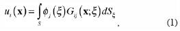
where ui(x) is the ith component of the displacement at point x, Gij(x;ξ) is the Green's function, which represents the displacement produced in the direction i at x due to the application of an unit force in direction j at point ξ, øj(ξ), is the force density in the direction j at point ξ. The product øj(ξ)dSξ in the integral represents the distribution of forces at the surface S. The suffix in the differential operator shows the variable on which the integration is carried out. This integral representation for displacements can be obtained from Somigliana's identity (Sánchez–Sesma and Campillo, 1991). It was proved that if øj(ξ) is continuous along S, then the displacement field is continuous across S (Kupradze, 1963).
This integral representation allows the calculation of stresses and tractions by means of the direct application of Hooke's law and Cauchy's equation, except at boundary singularities, this is when x is equal to ξ on surface S. From a limiting process based on equilibrium considerations around an internal neighborhood of the boundary, it is possible to write, for x on S,
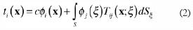
where ti(x) is the ith component of the traction associated to a direction n(x) in a smooth boundary S, c = 0.5 if x tends to the smooth boundary from inside the region. c=–0.5 if x tends to S from outside of the region, c=0 if x is not at S. Tij(x;ξ) is the traction Green's function, that is to say, the traction in the direction i at a point x with associated direction n(x) due to the application of an unit force in the direction j at ξ on S. The first term of the right–hand side of eq. (2) must be equal to zero if x is not on the surface S. Green's functions for traction and displacements can be found in Rodríguez–Castellanos et al. (2005) and (2006).
Boundary Conditions
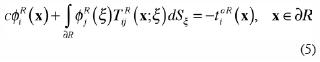
Traction–free boundary condition is reached at the free surface (∂R), including crack faces, and this can be written as:
Developing the boundary conditions and considering the incident and diffracted field, eq. (3) can be expressed as
where, tioR (x)= free–field traction in the Region R, as if the crack did not exist, tidR (x)= diffracted–field traction due to the presence of the crack. Then, eq. (4) can be written as
This equation represents a system of integral equations for boundary sources, i.e. those producing the diffracted field.
To solve the above integral equation system, we have to discretize them along a finite portion of the boundary that contains the crack or cracks. The cracks are considered as mathematical ones and then cero crack thickness is taken into account. Let us suppose that the force densities øj(ξ) are constant over each of the boundary elements with equal length ΔS along the boundary. If we assume that N is the number of elements along the discretized part (free surface of the Figure 1), we can obtain
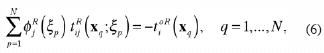
where,
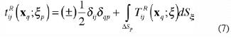
these integrals are calculated numerically, except when x= ξ. In such case, the right side term has to be dropped out, therefore we have
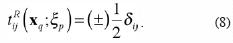
This discretization leads to a linear system of 2N equation with the same number of unknowns. The system is solved using Gauss method. Once the values of øj(ξ) are known the diffracted field is computed by means of the appropriate discretization of equation (1). In the following section we apply our integral formulation to solve Rayleigh– wave propagation in a surface–breaking cracked medium.
Numerical examples
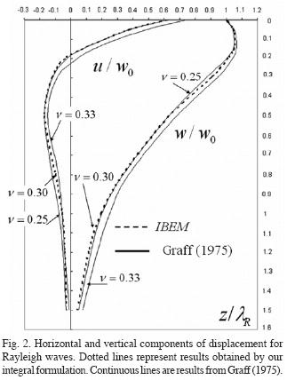
First, we validate our method, in frequency domain, applying it to an uncracked medium. In Figure 2, components of the Rayleigh wave motion, obtained by our integral formulation, are plotted. Normalized horizontal (u/w0) and vertical (w/w0) displacements against normalized depth (z/λR), for several Poisson's ratios ( 0.25, 0.30 and 0.33), are compared. The components u and w represent the displacements in the directions x and z, respectively. lR means one Rayleigh wavelength and w0 is the vertical displacement measured at the free surface. For this simulation, we take the following elastic properties: n=0.3 and b=1.0, as taken by Graff (1975). Good agreement can be observed between our results and those of Graff (1975). Moreover, the validation and application of the IBEM to subsurface crack problems can be seen in Rodríguez–Castellanos et al. (2005, 2006). The specified free field (Rayleigh–wave field as shown in Figure 2) has been implemented in several cases (see, Sánchez–Sesma and Campillo (1991) for 2D problems and Sánchez–Sesma and Luzon (1995) and Luzón et al. (1997) for 3D ones). In this figure one can appreciate that the major part of energy is concentrated near the free surface and that, for both components of displacement, the influence of the Rayleigh– wave disappears near , which is in agreement with theory. One can also notice that horizontal displacement changes of sign near , which is a notable indication of the retrograde motion of Rayleigh–waves.
To show the application of our integral formulation to a cracked medium, we have applied it to various cases, where the number and orientation of surface–breaking cracks vary. Initially, a vertical surface–breaking crack is considered with five crack depth ratios, which are d/a=0.1, 0.2, 0.4, 0.6 and 1.0 (a is taken as a reference parameter). We selected these simple crack configurations in order to validate our results with those obtained by other authors, as shown below. The properties of the medium are: tpβ/a=1 (β and t are the shear wave velocity and time, respectively) and (Poisson's ratio). We compute, in the frequency domain, the displacement field for 64 frequencies up to 3.848 Hz at various surface receivers. In order to simulate motion along time we used the FFT algorithm (Fast Fourier Transform) to calculate synthetic seismograms using a Ricker wavelet with characteristic period of tp β/a=1.
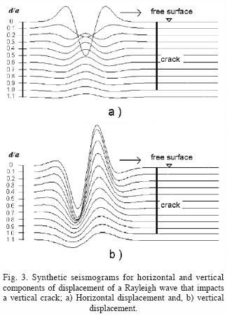
In Figure 3, temporal representation of the Rayleigh–wave pulse is shown. Horizontal and vertical displacements (Figure 3a and 3b, respectively) are depicted in order to show their amplitude with respect to depth and crack length. The wavelength selected to interact with the crack was λR/a=1, this is equivalent to d/a=1. Thus, the deepest crack considered here corresponds to d/a=1.0. Easily appreciated is the fact that in Figure 3 an accumulation of energy is concentrated at a distance shorter than one wavelength (Rayleigh, 1885; Hess, 2002; Wong, 1982; Graff, 1975). This important feature can be observed again on the horizontal component, where a simultaneous change on the particle motion is also identified at 0.2λR.
In Figure 4, horizontal (left) and vertical (right) displacements represented as synthetic seismograms for crack depth ratios of d/a=0.1, 0.4 and 1.0 (upper, middle and lower, respectively) have been plotted for this one vertical crack model (in all cases, the 26th–receiver is placed just at the crack and plotted with an horizontal line). In all cases wave amplifications can be observed for the nearest receiver placed at the left side of the crack, where the surface wave impacts. For the deepest crack model (d/a=1) the reflected and transmitted waves for the two components of displacement are clearly defined. However, when the crack becomes shallower, the diffracted wave field for horizontal component shows more complicated patterns for the receivers behind the crack. In the case of vertical components, when the crack depth ratio is d/a=0.1 , the transmitted amplitude of the wave is almost equal to those of the incident wave and the wave amplification at the crack is almost negligible. For the other cases, d/a=0.4 and d/a=1.0, the amplitude of transmitted waves are reduced while those of reflected ones increases.
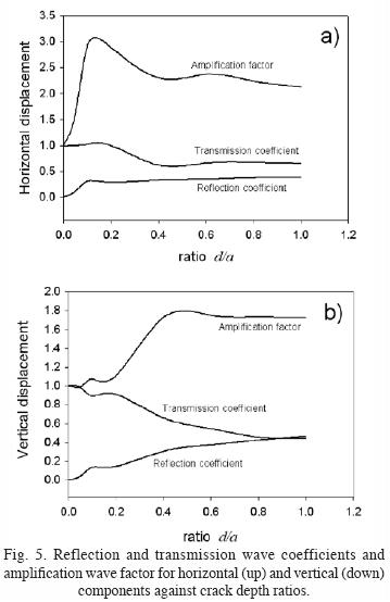
In Figure 5, transmitted and reflected wave coefficients and amplification wave factor are plotted, using the same one vertical crack model with the crack depth ratios mentioned above. Here, we define such coefficients and factors as the ratio between the transmitted, reflected wave amplitude and the incident wave amplitude. For the case of horizontal component (Figure 5a), amplifications of almost 3 times for the ratio d/a=0.1 are seen and for the ratio d/a=1 that value grows twice. For the case of d/a=1.0 the reflection coefficient corresponds to 0.35 (as obtained in Bray and Stanley, 1997), which was found for the case of a Rayleigh–wave that impacts on a corner). For lower ratios of d/a, transmitted wave coefficients tend to 1.0 and reflected ones to 0.0. Similarly, for vertical component (Figure 5b) wave amplifications reach almost 1.8 times for ratios d/a>0.4 and transmitted and reflected wave coefficients reach almost a factor of 0.45 times (these amplifications can also be seen in Kromine, 2000).
To study scattering of surface waves by multiple surface–breaking cracks we have analyzed three cases with five cracks each. The first one corresponds to cracks with ratio d/a=0.1, b/a=1.0 and θ=90°, the second to θ=135° and the last one to θ=45° (see Figure 1). It is important to mention that these models were selected in order to show the use of our integral formulation dealing with strong–scattering media. Many other crack configurations could be of interest. However, we do believe that these simple models allow us to perceive important features about the diffraction of Rayleigh waves by surface–breaking cracks. In Figure 6 synthetic seismograms for the studied cases are shown (upper, middle and lower, respectively). In Figure 6a the horizontal component of displacement is strongly influenced by cracks, showing amplifications of almost 3 times with respect to the incident wave (as mentioned in Figure 5a). However, finally slight wave attenuation at the last receiver can be seen. The vertical component shows similar behavior, because the incident wave is affected at cracked zone, but finally slight attenuation at the last receiver is again obtained.
In the case of vertical and horizontal displacements for θ=135° insignificant attenuations and amplifications are observed (Figure 6b). As well, for the case of θ=45° (Figure 6c) only small amplification and attenuation are seen for both components of displacement. We believe that for these two last cases the crack orientation does not affect the Rayleigh– wave propagation. This can be attributed to the small distance between the crack tip and the free surface and their orientation. From these analyses we can say that the crack depth and orientation are crucial to identify a medium with several cracks. A damaged surface could not be recognized if the incident pulse is not applied at the right direction or with the proper wave amplitude.
Conclusions
In the present paper we have analyzed the effect that one or several surface–breaking cracks have on the propagation of Rayleigh–waves. We have briefly shown the formulation of the Indirect Boundary Element Method applied to the propagation of surface waves in a halfspace containing surface–breaking cracks. Attenuation, reflection and amplification of Rayleigh–waves by several crack depths have been studied with good detail. We have concluded that the horizontal component of displacement of Rayleigh–waves is more affected by shallow cracks, where strong amplification can be seen (almost 3 times of the incident wave). However, for the case of vertical component the amplification reaches 1.8 times the incident wave for ratios d/a>0.4. From the multiple diffraction results (Figure 6), we have found that surface–breaking cracks influence strongly the propagation on surface waves. In fact, it is well known that the major amount of energy of the Rayleighwaves is located around the free surface. In that sense, surface–breaking cracks may produce different attenuation depending upon depth and inclination. Given surface wave polarization, has been pointed out that the vertical component appears to be slightly affected by the presence of cracks. A damaged surface could not be recognized if the incident pulse is not applied at the right direction or with the proper wave amplitude. We believe that the results presented in this paper are of interest to the scientific community given their usefulness as benchmark solutions to calibrate other numerical techniques. The information reported here may provide to the field engineers a way to recognize patterns and behavior of surface–breaking cracks from the analysis of the diffracted field.
Acknowledgements
We thank to two anonymous reviewers for their useful comments to improve and clarify this manuscript. This work was supported by Instituto Mexicano del Petróleo, under Petroleum Exploration Research Program, Project D.00393; by Petróleos Mexicanos (PEMEX), Mexico, under grant 410305846 and from DGAPA–UNAM, Mexico, under grant IN114706.
Bibliography
Achenbach, J. D., A. K. Gautesen and D. A. Mendelshn, 1980. Ray analysis of surface–wave interaction with an edge crack. IEEE Trans. on Sonics and Ultrasonics, 27, 124–129. [ Links ]
Bray, D. E. and R. K. Stanley, 1997. Nondestructive evaluation, a tool in design, manufacturing and service. CRC pres, 82. [ Links ]
Graff, K. F., 1975. Wave motion in elastic solids. Ohio State University Press. 327. [ Links ]
Hess, P., 2002. Surface acoustic waves in materials science. Physics Today, 42–47. [ Links ]
Kromine, Fomitchov, Achenbach, Krishnaswamy, 2000. Scanning laser source technique for crack detection. Materials Eval. 58. [ Links ]
Kundu, T. and A. K. Mal, 1981. Diffraction of Elastic Waves by a surface Crack on a Plate. Trans. of the ASME. 48, 570–576. [ Links ]
Kupradze, V. D., 1963. Dynamical problems in elasticity, In Progress in Solid Mechanics. I. N. Sneddon and R. Hill (eds), North–Holland, Amsterdam, vol. III. [ Links ]
Luzón, F., F. J. Sánchez–Sesma, J. L. Rodríguez–Zuñiga, A. M. Posadas, J. M. García, J. Martín, M. D. Romacho and M. Navarro, 1997. Diffraction of P, SV and Rayleigh waves by three–dimensional topographies. Geophys. Int. Journal. 129, 571–578. [ Links ]
Mal, A. K., 1980. Diffraction of SH waves by a near surface crack. Review of Progress in Quantitative Nondestructive Evaluation. Vol. 1, Plenum Press, New York, 499–503. [ Links ]
Mendelsohn, D. A., J. D. Achenbach, and L. M. Keer, 1980. Scattering of elastic waves by a surface–breaking crack. Wave motion. 2, 277–292. [ Links ]
Pecorari, C., 1996. Modeling variations of Rayleigh wave velocity due to distributions of one–dimensional surface–breaking cracks. J. Acoust. Soc. Amer. 100, 1542–1550. [ Links ]
Rayleigh, J. W. S., 1885. Proc. London Math. Soc. 17. [ Links ]
Rodríguez–Castellanos, A., F. Luzón and F. J. Sánchez–Sesma, 2005. Diffraction of seismic waves in an elastic cracked half–plane using a Boundary Integral Formulation. Soil Dynam. and Earthq. Enging. 25, 827–837. [ Links ]
Rodríguez–Castellanos A., F. J. Sánchez–Sesma, F. Luzón and R. Martin, 2006. Multiple scattering of elastic waves by subsurface fractures and cavities. Bull. Seis. Soc. of Am., 96, 1359–1374. [ Links ]
Ruiz, L. A. and P. B. Nagy, 2002. Diffraction correction for precision surface acoustic wave velocity measurements. J. Acoust. Soc. Am., 112, 835–342. [ Links ]
Sánchez–Sesma F. J. and M. Campillo, 1991. Diffraction of P, SV and Rayleigh waves by topographic features; a boundary integral formulation. Bull. Seism. Soc. Am., 81, 1–20. [ Links ]
Sánchez–Sesma, F. J. and F. Luzón, 1995. Seismic response of three–dimensional alluvial valleys for incident P, SV and Rayleigh waves. Bull. Seism. Soc. Am., 85, 269–284. [ Links ]
Scales, J. A. and K. V. Wijk, 1999. Multiple scattering attenuation and anisotropy of ultrasonic surface waves. Applied Phys. Letts., 74, 3899–3901. [ Links ]
Stone, S. F., M. L. Ghosh and A. K. Mal, 1980. Diffraction of Antiplane shear waves by an Edge Crack. J. Appl. Mech., 47, 359–362. [ Links ]
Suh, D. M., W. W. Kim and J. G. Chung, 1996. A Rayleigh wave technique for detection and sizing of small cracks in studs and bolts. IEEE ultrasonics symposium. 673–676. [ Links ]
Tittmann, B. R. and L. A. Ahlberg, 1986. Rayleigh wave diffraction from surface–breaking discontinuities. Appl. Phys. Lett., 49, 1333–1335. [ Links ]
Wong, H. L., 1982. Effect of surface topography on the diffraction of P, SV and Rayleigh waves. Bull. Seism. Soc. Am., 72, 1167–1183. [ Links ]

