


 nueva página del texto (beta)
 Inglés (pdf)
 Artículo en XML
 Referencias del artículo
 Enviar artículo por email
 Citado por SciELO
  Similares en
SciELO
Similares en
SciELO 
 Permalink
Introduction
Some of the most important engineering ceramics are alumina (Al2O3), silicon nitride (Si3N4), silicon carbide (SiC) and zirconia (ZrO2) combined with some other refractory oxides. Of all advanced ceramics, silicon nitride probably has the most useful combination of properties for industrial purposes, such as diesel engine valves, components exposed to thermal shocks, bearings, and other slipping surfaces where they must have good mechanical properties at high temperatures, high hardness, low thermal conductivity and high wear resistance (Matizamhuka, 2018; Richerson, 2012; Schmid, 2002). The possible applications in materials engineering make the development of strategies to obtain these ceramics very broad (Lenoe et al., 2013). Ceramic materials, in addition to being very hard and resistant to wear, have good resistance to compressive stress compared to other types of materials; therefore, are ideal for use in bearings. Despite having these characteristics in their favor, the high brittleness and low toughness of these materials was always an obstacle to the mass production of ball bearings; however, in 1972 silicon nitride emerged as the first successful ceramics for the manufacture of high-speed and high-load bearings (Richerson, 2012; Riley, 2000). All the properties of the ceramic materials are affected by the microstructure, therefore, the key to control the performance of a ceramic material is its microstructure during processing, while controlling the morphology and distribution of the microstructural elements (stoichiometry, size, shape and crystalline configuration of the grains, distribution, orientation, arrangement, chemical characteristics of the present phases and their grain boundary) so that the various properties are compatible with the material (Yang et al., 2002). The ceramic materials based on silicon nitride are prepared from powders constituted by a phase α which are converted into sintering at phase β. In this way, the final microstructure of these is composed of β-Si3N4 phase grains (in many cases totally), and small proportions of α-Si3N4 phase grains that do not achieve their transformation (Bellosi & Babini, 1999). This bimodal structure is characterized by the mixing of small and equiaxial grains, corresponding to the α-Si3N4 phase, with elongated grains of generally fibrous morphology, belonging to the β-Si3N4 phase (Bondanini et al., 1999). Among the most relevant points determining the microstructural characteristics of the silicon nitrides are the proportion and the size of the phase a in the starting powders, the temperature and the sintering time, the volume of the liquid phase, the viscosity and the solubility of the nitrogen in the liquid. Sintering additives also play an important role in the final microstructure of silicon nitride materials and it has been found that when they are added in certain percentages the densification increases and the transformation is favored to the phase β-Si3N4 which is very important to improve the mechanical properties of the material, especially the fracture toughness (Zhou et al., 2006), which is limiting in many of its possible applications in the engineering area due to the brittleness of the ceramic materials, especially in those components subject to cyclic stress loads, however, through some microstructural manipulation mechanisms that have been developed during the last decades, have made it possible to counteract, to some extent, these effects; drastically increasing the fracture toughness of these materials to make them competitive with materials such as foundries (Weimer, 2012). The increasing demand in the use of these new materials warrants having the data necessary to predict its behavior and its useful life under the conditions of service for which its use is projected (Richerson, 2012; Zhou et al., 2006). In this way, the tests for determination fracture toughness and its elastic modulus become indispensable to establish the patterns of design and use of these new materials, taking into account that it is necessary to have a greater reliability as well as, a better prediction of the performance of the mechanical components in which they will be used to operate efficiently, even under more severe operating conditions in terms of high temperatures, loads and speeds (Melendez, 2001). The mechanical failure of the ceramic materials is mainly due to structural defects. The main causes of fracture in polycrystalline ceramics are due to surface cracks produced during surface finishing processes, pores, or inclusions produced during processing. In preliminary investigations, it has been determined that materials possessing low toughness tend to develop a system of radial medial crack, whereas materials with high fracture toughness are favored by the palmqvist system of cracks (Cook et al., 1964). However, recent investigations (Chicot et al., 2004) have found that many materials exhibit both cracking systems and that their occurrences will depend on the level of loading applied to the indentation. In this sense, studies by Cook & Braun (1994) and by Kaliszewski et al. (1994), indicate that at low loads cracks of the palmqvist type are formed and that this morphology changes to radial medians when the applied load over-passes a limit load value; this limit value depends on the material being tested, therefore, in addition to the interest of the calculation of the fracture toughness and the elastic modulus of these ceramic materials, will also be verified through this research the system of cracks that predominates when subjected to loads and the effect of the temperature is these properties, it should be noted that these ceramic materials are suitable for selection with other materials such as metal, having as an initial disadvantage its high price. In this sense, the prediction of fracture toughness of these materials becomes a universal challenge crucial for the successful application of new materials in different technologies, a framework in which this research is intended to be introduced.
Experimental
Obtaining samples
The samples used in this study were produced in collaboration with the Institute of Ceramics Research located in Faenza, Italy. Commercial silicon nitride powders (without additives) of brand UBE SNE10®, whose characteristics are presented in Table 1, were used for its manufacture.
Table 1: Characteristics of the silicon nitride powders used to obtain the samples
| Characteristics | Powders of Si3N4 | |
| Specific surface area (s.s.a ) [m2/g] | 11.5 | |
| Average particle size [µm] | 0.19 | |
| Average additive size [µm] | 0.7 | |
| α- Si3N4 [Vol %] | 95.0 | |
| Impurity [wt %] | O | 1.4 |
| Ca | 0.005 | |
| Fe | 0.010 | |
| Al | 0.005 | |
| Cl | 0.010 | |
| Atomic relation | N/Si | 1.0 |
| Si/O | 2.2 | |
| N/O | 2.2 | |
From these powders two types of samples were produced, using as sintering additives powders of La2O3, Y2O3, and Al2O3. The proportions of these additives, as well as the compositional characteristics of each type of sample, are presented in Table 2. The selection of these compositions for the manufacture of the samples is based on previous results reported by several researchers for the which have obtained the best microstructure characteristics and the best mechanical properties for these materials (Shaw & Pethica, 1986).
Table 2: Identification and composition of the samples
| Samples | |||
| Si3N4-A | Si3N4-B | ||
| Additives [wt %] | 3% La2O3+3% Y2O3 | 3% Al2O3+8% Y2O3 | |
| Specific surface area [m2/g] | 12.0 | 10.3 | |
| Impurity [wt %] | O | 3.4 | - |
| N | 38.3 | - | |
| Y/Si | 0.018 | 0.16 | |
| Atomic relation | La/Si | 0.0102 | - |
| Al/Si | |||
| - | 0.15 | ||
Si3N4-A* and Si3N4-B* identification the samples with post-heat treatment
The process of incorporating the sintering additives into the silicon nitride powder (as shown in Figure 1) was done by mechanical mixing of the powders by stirring with silicon nitride beads in alcohol-isobutyl in a closed polyethylene vessel for a time of 24 hours. The powder mixtures were densified by hot isostatic pressing to the vacuum, in an induction furnace using a graphite dice at a temperature of 1850 °C, a time of 30 minutes for the samples identified as Si3N4-A, and 1700 °C for 60 minutes for the samples identified as Si3N4-B, in both cases, a constant pressure of 30 MPa was used.
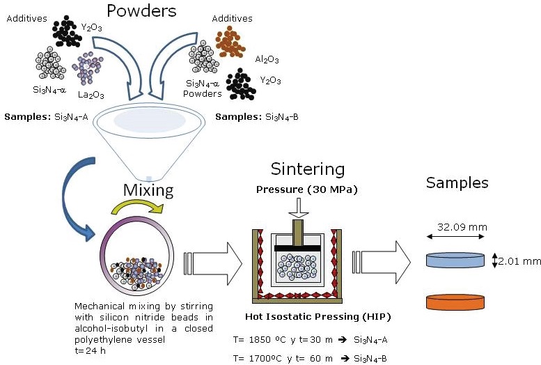
The conditions of the heating and cooling stages, as well as the time in each of the stages, have been studied previously (Bellosi & Babini, 1999). The manufactured samples have a disk shape with dimensions of 32.09 mm in diameter and 2.01 mm in thickness. The microstructural characterization by Scanning Electron Microscopy and the determination and quantification of the phases by X-ray diffraction for these samples was carried out in a previous work in which the influence of the additives (La2O3, Y2O3 and Al2O3) was evaluated in the microstructure and properties of silicon nitride (Carrasquero et al., 2005).
In order to corroborate the results presented by Yang et al. (2001), who demonstrated by a comparative study with silicon nitride (with and without subsequent heat treatment) that it is possible to promote the crystallization of phase interactions and the elimination of their stresses, and thus an improvement in the fracture toughness of these materials. In order to evaluate such effect of the temperature on the values of the mechanical properties initially obtained by the sintering process, a heat treatment was carried out after 300 °C to a group of samples in a furnace in an argon atmosphere for a period of 6 hours, subsequently verifying if there were changes in the values of the mechanical properties.
Determination of the elastic modulus (E)
For the measurement of the elastic modulus (E), the instrumented indentation technique was used in a CSEM® brand equipment with a Vickers type pyramidal tip indenter. For the calculation of the elastic modulus, the equipment performed the automatic calculation based on the procedure established by Pharr & Oliver (1992). Five indentations were performed for different charge values from 25 to 300 g. For both types of samples, a Poisson coefficient ν = 0.26 was used, the approximation speed of the tip of the indenter to the surface of the sample was 10 nm/s. The time used in both the loading and unloading process was 10 s and the waiting time after the test load reached
Determination of fracture toughness (Kc)
For the measurement of fracture toughness, the Vickers indentation method was used. Before the indentations were carried out on the samples, the surface preparation of the samples was carried out, which were surface preparation using polishing disks with diamond particles of 120 and 200 μm, followed by a polishing with a suspension of alumina of 1 and 0.3 μm. Six indentations per charge applied to the two types of silicon nitride were carried out using a macro-hardness tester Wollpert universal using loads of 294, 196, 147 and 98 N and a dwell time of 60 s was imposed at the maximum load. The macro-hardness tester was equipped with a Vickers diamond pyramid indenter. Subsequently, the diagonals of the indentation were measured as well as the length of the cracks they generated, with the aid of an optical microscope coupled to an image analyzer. The measurements allowed to calculate the parameters c, a and l shown in Figure 2 and that are used for the calculation of the toughness following the procedure proposed by Ponton & Rawlings, (1989), where the parameter "c", (equals the sum of the average length of the cracks produced under the indentation and half of the average length of the indentation diagonal) must be calculated in both directions of the indent.

Determining the system of cracks that occur in the material under the loads being applied is of vital importance since the equations for establishing the value of toughness are related to the type of crack formed. Ponton & Rawlings, (1989), generalized the equations belonging to the groups of the following way:
where:
E and HV = |
modulus of elasticity and Vickers hardness of the sample, respectively |
P = |
applied load in the indentation |
c, α and l = |
lengths of the parameters presented in Figure 2 |
α, β, r and q = |
parameters that vary according to the author who proposing the equation |
M or P in the term KC = |
the type of crack system that is formed (M corresponds to the system of median radial cracks and P corresponds to the system of cracks type palmqvist |
According to Ponton & Rawlings, (1989), the most used equations for the calculation of fracture toughness by the Vickers indentation method are the following:
Equation proposed by Anstis et al. (1981):
Equation proposed by Evans & Charles (1976):
Equation proposed by Gong et al. (2002):
This three equations assumes as mode of cracking the median-radial type if the ratio between the length of the crack to the half of the indent diagonal, c / a ≥ 2. For the second case, corresponding to the system of cracks type palmqvist the equations proposed by Niihara et al. (1982) and Shetty et al. (1985) which indicate that if c/a ≤ 3, the characteristic length would be given by the average length of cracks measured from the vertex of the indentation, l, instead of c. Thus, for values of l/a in the range from 0.25 to 2.5, the Niihara & Shetty equations can be expressed as follows, respectively:
To determine which expression is the most adequate to perform the calculation of fracture toughness, the criterion established by Chicot et al. (2004) was used. These researchers posed the determination of the slope of the line that is obtained by plotting the relation of ln(c/a) vs. ln(P). If the slope of the line obtained with the experimental values approaches a value of 1/2, it is estimated that the system of cracks is type palmqvist, and if it has a value close to 1/6 the system of cracks that predominates is the radial median type.
Determination of hardness
Measurements were made through a Wollpert durometer, with an attached Vickers indenter, using loads 10, 15, 20 and 30 Kg. For the calculation of the hardness, the following equation was used (Gong, 1999):
Results and discussion
Elastic module
The results obtained from the determination of the elastic modulus (E) are shown in Figure 3. It is seen in Figures 3a and 3c that for both types of silicon nitrides there is a similar behavior indicating a decrease of (E) with the indentation load, reaching a constant value of 250 GPa from a load of 3 N. In the literature, values of the elastic modulus ranging from 290-325 GPa for silicon nitride have been reported depending on the composition, processing and the method of measurement used (De Pablos et al., 2003). For example, for the same composition of the Si3N4-A samples, (Bondanini et al., 2001) obtained a value of the elastic modulus of 325 GPa using the ultrasound resonance technique, this value is higher than that obtained by microindentation. However, by using the procedure established by Pharr & Oliver, (1992), more discrete values of the elastic modulus are guaranteed as a function of the set of phases present in the microstructure compared to the general value that is obtained when using the ultrasound technique. After the thermal treatment of the samples, the elastic modulus was measured again to evaluate if the samples underwent any change of this property due to the temperature effect (Figures 3b and 3d); even though the elastic modulus decreases with respect to the indentation load, there is a decrease in its value of approximately 100 GPa for both kinds of nitrides, being 150 GPa from the load of 3 N. It is evident that effectively the value of the elastic modulus has been influenced by the increase of the temperature, due to the diffusion mechanisms as reported by Yang et al. (2000) that the use of subsequent thermal treatments promotes the crystallization of larger quantities of refractory phases in the grain boundaries of β-Si3N4 phase, thus reducing the residual stresses produced by the sintering process.
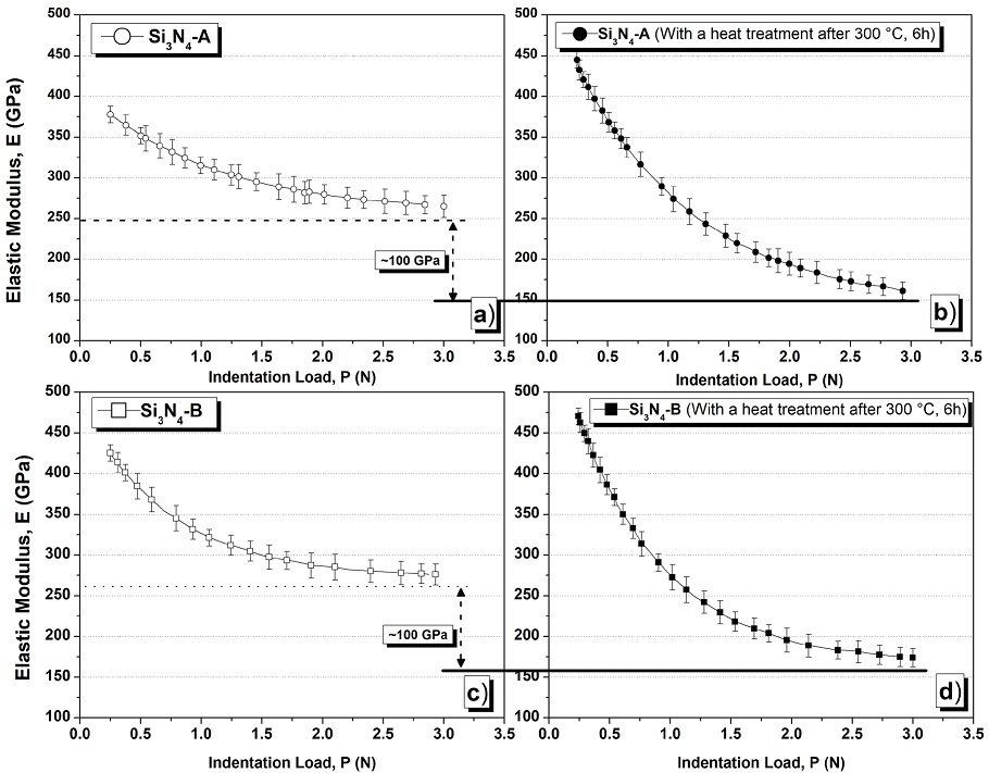
Figure 3: Variation of the elastic modulus with respect to the indentation load, a) sample Si3N4-A; b) sample Si3N4-A with a heat treatment after 300 °C, 6 h; c) sample Si3N4-B; d) sample Si3N4-B with a heat treatment after 300 °C, 6 h
For the determination of the fracture toughness of the samples, the value of the elastic modulus of 250 GPa was considered for both types of nitrides in initial condition and 150 GPa for the samples that were submitted to the heat treatment after 300 ºC by 6 h .
Fracture Toughness (Kc)
Figures 4 and 5 show the variation of the fracture toughness (Kc) with the indentation load for each of the equations presented in the literature both types of samples, with and without post-heat treatment.
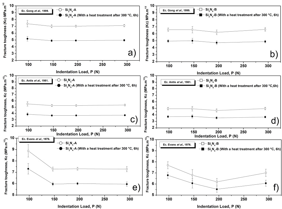
Figure 4: Fracture toughness values (Kc) for radial median cracks system: a) and b): using the Eq. Gong et al. (1999); c) and d): using the Eq. Anstis et al. (1981); e) and f): using the Eq. de Evans et al. (1976)
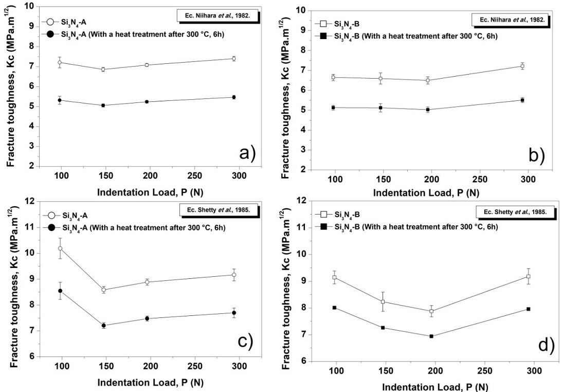
Figure 5: Fracture toughness values (Kc) for system of cracks type palmqvist, a) and b) using the Eq. de Niihara et al. (1982); c) and d) using the Eq. Shetty et al. (1982)
With these results, the method proposed by Chicot et al. (2004), to know in advance which crack system predominates in the load range used and to know which equations represent the most reliable values. For this, we calculated the slope of the line obtained by plotting the relation of ln(c/a) vs. ln(P). In Figure 6, these relations and their respective equations of the lines obtained by the linear regression method of the experimental data are represented.

Figure 6: Determination of the crack system: a) sample Si3N4-A; b) sample Si3N4-A with a heat treatment after 300 °C, 6 h; c) sample Si3N4-B; d) sample Si3N4-B with a heat treatment after 300 °C 6 h
The slopes of the lines for Si3N4-A and Si3N4-B (Figure 6) have an approximate value of 0.14 and 0.15 for both types of nitrides and with a heat treatment after 300 °C, respectively; all the slopes of the lines are closer to the value of 1/6 than the value of 1/2 , so it is concluded that the silicon nitride develops predominantly in the load range under study a system of radial cracks for both compositions and regardless of whether they have undergone changes or not by the effect of temperature Chicot et al. (2004). It should be noted that this same system of cracks coincides with the results of the work done by researchers (Lube, 2002; Miyazaki et al., 2010; Ordoñez, 2013), who reported that from the 98 N of applied load on the indentation the radial median crack system for this type of ceramic material is developed. Once it was known which crack system predominated, it was analyzed which of the equations formulated for this type of system, represents the best results of fracture toughness in comparison to those reported in the literature. Using the equation proposed by Evans et al. (4), slightly higher fracture toughness values were recorded for Si3N4-A than Si3N4-B, however, among the samples that suffered the effect of temperature (Si3N4-A* and Si3N4-B*), the toughness values are very similar, with a reduction of approximately 22 % and 13 % with respect to the initial samples. For any of the cases, the values of the use of this expression are higher in comparison with those obtained using the equation of Anstis et al. (3), since it is not considered term of the relationship between the elastic modulus and the hardness of the material for the calculation of the fracture toughness. The results obtained using the equation proposed by Anstis et al. The highest values of Kc correspond to Si3N4-A with respect to Si3N4-B, even for those that suffered the effect of temperature.
In contrast to the results obtained by the Evans equation (4), it can be observed that the values of Kc practically remain constant with respect to the applied load, due to the fact that in this case, if the value of the elastic modulus and the hardness of the material for the load used. The effect of the temperature on the fracture toughness generated a reduction of the Kc value in the order of 43 % and 23 % for Si3N4-A and Si3N4-B, respectively.
Evaluating the results obtained using the equation proposed by Gong et al. (5), as in the previous case, the highest values of Kc correspond to Si3N4-A. Very similar values of Kc are obtained for the samples that underwent the effect of temperature. However, when using this equation, a decrease in fracture toughness value of 43 % and 33 % was recorded for the Si3N4-A* and B* samples, respectively. Comparing the values obtained by using the equation of Anstis et al. (1), This expression proposed by Gong (1999) which is a modification Lawn et al. (1980), who considered the use of the apparent hardness of the material, while Gong et al. (2002), used an empirical expression for obtaining the real hardness, independent of the geometry of the indenter and the way the load is applied, however, it is not taken into account the elastic constants of the material, the friction effect in the contact and how the material flows under the indenter. It is important to take into account at the time of the determination of Kc by the Vickers indentation method the effect of the change of hardness with the applied load or better known in the literature as the effect of the size of the indentation in the hardness (ISE), this effect generates a problem in the selection of the load to be used to obtain a correct Kc value, this is because the equations used are deduced from values of constant hardness, thus introducing systematic errors in the calculation of Kc.
Hardnees
Figure 7 shows how the hardness with respect to the applied load varied for the four samples under study. The hardness of the Si3N4 varies with the load until reaching a constant value, obtaining for both types of nitrides a value of approximately 18 GPa, whereas for samples Si3N4-A* and B* this value is close to 15 and 14 GPa, respectively. These results agree with those presented in the research carried out by Bellosi & Babini, (1999), which reported hardness values for silicon nitrides measured under Vickers microindentation at a load of 9.81 N, values of 18.6 ± 0.3 GPa for Si3N4-A and 17.3 ± 0.4 GPa for Si3N4-B. As can be seen in Figure 7, there is a small difference between the samples and that they are closely linked to their compositions which, as already mentioned, is responsible for the final microstructural characteristics of the material and, therefore, the mechanical properties they exhibit.

Figure 7: Variation of the hardness with respect to the applied load in the indentation: a) sample Si3N4-A with and without post-heat treatment; b) sample Si3N4-B with and without post-heat treatment
These results are corroborated to those reported by Zutshi et al. (1994), who evaluated the Vickers hardness variations in different types of silicon nitride, finding that they are associated to any changes related to the composition of the grains and morphology. In order to calculate the fracture toughness of all the samples studied, the load at which the hardness reached a constant value (P ≥ 147 N) was taken into account and also ensured that the cracking produced was not excessive or to produce non-uniform tracks as recorded at the maximum load (P = 294 N). With the use of P ≥ 147 N the best results are obtained in the fracture toughness measurements in this type of material since from this load it was obtained that the parameter P/c3/2 remained constant verifying the review (Lube, 2002).
Generally and independently of the equation used for the determination of Kc, the highest values corresponded to Si3N4-A and Si3N4-A* in comparison to the other two respective samples. From the microstructural point of view, these results are in agreement with the literature for this type of material, since there is a well-defined relationship between microstructure and fracture toughness as a function of how it interacts with cracks through the mechanisms of deflection, separation of grains and branching of cracks and where there are two key parameters in the microstructure that give indications of how they act as it is size and shape relationship of the β-Si3N4 phase. The effect of grain size on the toughness has already been studied by others (Matsuhiro &Takahashi, 2008), who reported that the polycrystalline Si3N4 with the same relation of form, the samples that had a bigger grain size presented a greater resistance to the propagation of cracks, often occurring deviations around large grains and dispersions of energy in the generation of secondary cracks. With regard to the shape relationship of the β-Si3N4 phase grains as it increases, the deflection mechanisms and crack bridges are more effective (Ordoñez, 2013). A previous investigation carried out for the same nitride composition (Carrasquero et al., 2005); where Si3N4-A presented interlaced elongated phase grains (β-Si3N4) with values of shape and grain size much lower than with respect to Si3N4-B and that the amount of residual α-Si3N4 phases was 13.77 % and 28.28 % for Si3N4-A and Si3N4-B, respectively.
These previous results explain the reason why the highest values Kc corresponded to Si3N4-A and Si3N4-A* in comparison to the other two Si3N4-B and Si3N4-B*, since the Si3N4-A has a higher value of grain shape ratio, fundamental parameter for the activation of the crack deflection mechanism, also contains a lower percentage of residual α- Si3N4 phase, as reported by De Pablos et al. (2003), where a lower content of this phase in the microstructure generates an increase in fracture toughness. An analysis of which of the three equations proposed in the literature for the radial median crack system (3, 4 and 5) express the closest toughness values to those obtained using conventional tests for determination of Kc of the silicon nitride manufactured under different methods reported in the literature is presented in Table 3.
Table 3: Fracture toughness values reported in the literature
| Reference | Composition Samples | Technique used | Fracture toughness KIC (MPa.m1/2) |
|---|---|---|---|
| (Ordoñez, 2013) | Si3N4 + 6 % Y2O3 + 4 % Al2O3, | CNB* | 5.60 |
| Si3N4 + 6 % Y2O3 + 4 % MgO | CNB | 5.20 | |
| (Zutshi et al., 1994) | Si3N4 + 2 % Y2O3 + 5 % Al2O3 | Indentation | 5.45 |
| (Gong et al., 2002) | Si3N4 | SEPB** | 6.10 |
| (Melandri et al., 1995) | Si3N4+ 3 % Al2O3 + 8 % Y2O3 | Indentation | 4.80 |
| (Wang & Mao, 1995) | Si3N4+ 5 % Al2O3 +2.5 % Y2O3 + 7.5 % La2O3 | CNB | 8.06 |
| (Kim et al., 1989) | Si3N4+ 3 % Al2O3 + 8 % Y2O3 | Indentation | 4.66 |
| (Bellosi & Babini, 1999) | Si3N4 + 3 % La2O3 +3 %Y2O3 | Indentation | 4.70-5.90 |
| Si3N4+ 3 % Al2O3 +8 % Y2O3 | Indentation | 4.80-5.50 | |
| (Liang et al., 1999) | Si3N4 + 6 % Y2O3 + 2 % Al2O3 | Indentation | 5.08-6.35 |
| (Lu & Huang, 2001) | Si3N4 + 6 % Yb2O3 + 2% Al2O3 | SEPB | 11.80 |
| Si3N4 + 6 % Y2O3 y 2 % Al2O3 | SEPB | 6.20 |
* Chevron-Notched Beam (CNB), ** Single-Edge Precracked Beam (SEPB)
Comparing the results obtained from the use of the three equations for the determination of fracture toughness for the radial medial crack system, we can show that equation of Anstis et al. (3) is the one that yields results comparable to the values reported in the literature by other writers, for similar compositions and microstructures, since they were obtained with the application of this equation values average Kc of 5.29 ± 0.13 MPa.m1/2 and 4.86 ± 0.27 MPa.m1/2 for Si3N4-A and Si3N4-B, respectively.
It should be pointed out that with the use of the Vickers indentation method for the calculation of fracture toughness (Kc) values very close to those of KIC can be obtained, with accuracy close to 30 % with respect to those reported in the literature (Ponton & Rawlings, 1989).
Conclusions
From the results presented in this work, it is concluded that in general and independently of the equation used for the determination by indentation of fracture toughness, the highest values corresponded to the silicon nitride samples modified with La2O3 and Y2O3 as compared to those modified with Al2O3 and La2O3, attributed to the microstructural characteristics generated by these sintering additives, which produced a self reinforced structure with a larger grain size and radius of appearance of the grains of the phase-β that favor the increase of the resistance to the fracture. A decrease of the elastic modulus in its value of approximately 100 GPa for both types of nitrides was also corroborated by the effect of the temperature at which the samples were subjected during the heat treatment after 300 °C, final value obtained is within the average values reported for these ceramic materials above 150 GPa. The use of the expression proposed by Anstis et al. (1981) is the one that yields comparable results to the values reported in the literature by other authors, for similar compositions and microstructures. By means of the indentation technique, the intrinsic fracture toughness of the material can easily and quickly be obtained without the need for more sophisticated and cumbersome methods, where larger samples and more complex geometries are required.
Therefore, the evaluation of the mechanical properties of the silicon nitride samples modified with La2O3+Y2O3 such, elastic modulus and fracture toughness indicates that the additions of rare earth gives rise to a significant improvement of the mechanical performance. Therefore, the outcome derived from the evaluation of the mechanical properties of the ceramic under study allow an explanation of the results previously reported in the literature concerning the improvement of the engineering ceramic.

